11. Input devices
Add a sensor to a microcontroller boardthat you have designed and read it
Electronics
Components
Temperature sensor

I followed this tutorial to setup the temperature sensor DS18B20.
Basic Features of the DS18B20:
- Unique 1-Wire Interface Requires Only One Port Pin for Communication
- Each Device has a Unique 64-Bit Serial Code Stored in an On-Board ROM
- Requires No External Components
- Can Be Powered from Data Line; Power Supply Range is 3.0V to 5.5V
- Measures Temperatures from -55°C to +125°C (-67°F to +257°F)
- ±0.5°C Accuracy from -10°C to +85°C
Distance sensor
To measure content of the fish container food, I decide to try the analog distance sensor, Sharp GP2Y0A60SZLF. I decide, to add one, or two inputs for distance, sensor, if I have time, I will use them. Finally I didn't use it.
USB
Inspied by this tutorial, I wanted to add an usb to my microcontroller. But, finally, I didn't add it because of time.
Design PCB
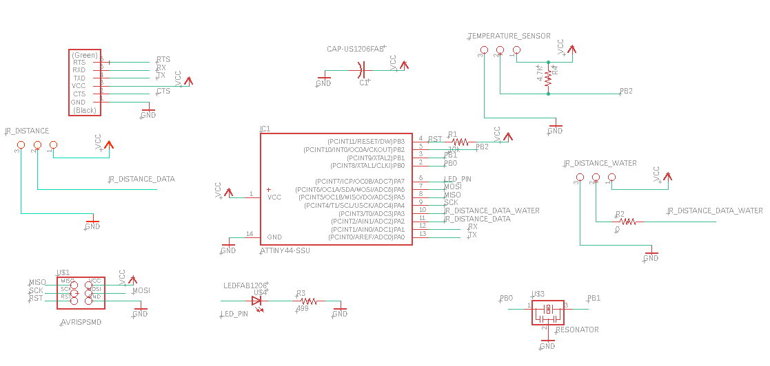
All the design was maid using Eagle. The board is based on the board of the electronic design, I used an attiny 44 with a resonator of 20Mhz, one led for debugging and then I added the two sensor tested with Arduino.
Schematics
Temperature sensor schematic
As describe in the datasheet (p7), use the one wire protocole to communicate with the microcontroler. 1-Wire is propietary protocol, where single "master" device communicates with one or more 1-Wire "slave" devices over a single data line. So reading from the datasheet, I saw that the one wire data output (PB2) needs to be connected to the VCC using one resistor of 4.7 KΩ.


distance sensor schematic
The sensor Sharp GP2Y0A60SZLF can be power by 5V or 3V, the only diffrence is one resistor of 0Ω populate or not. This analog distance sensor is easy to use, he have 3 output pins, one VCC, GND and another one, OUT for reading data from the microcontroller. The pin EN, is optionnal, and can be used to disable the emitter and save power, but in my case, I want be simple in first time, so I decide to not use it.

Overview
So this is the final schematics for this board:
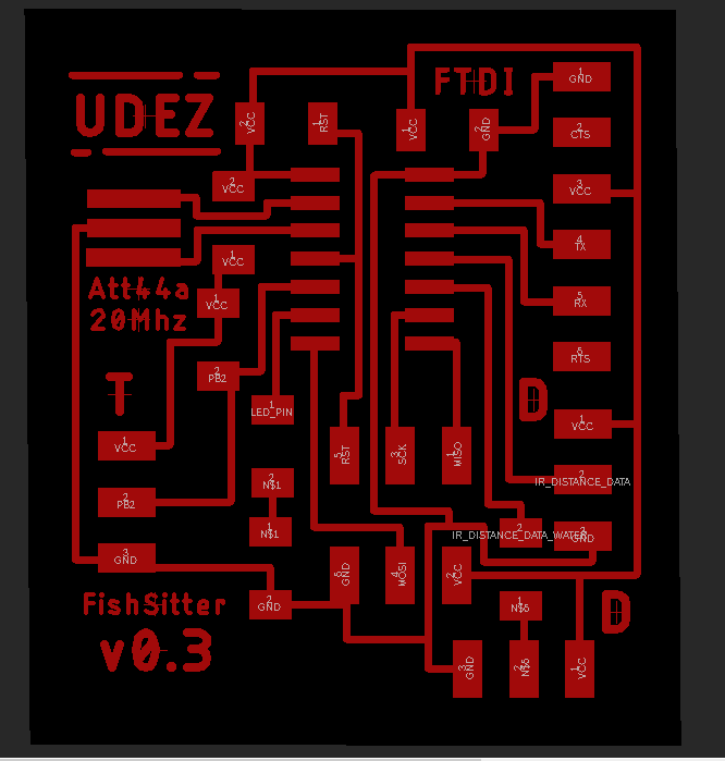
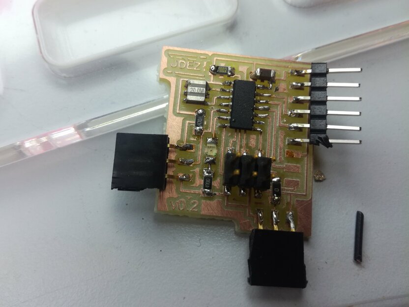
Board
For this board, I maid lot of itteration to fit all the components, based on my previous board, the majority of elements was easy to place. And this is the final board that I milled.

⚠️ Update, because I maid a wrong copy/past for the base of my board, I maid a mistake a forgot to connect the ground of the resonator, so, the right board should be this one:
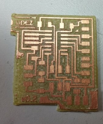
Production
Using the same configuration of the week of electronics production. ⚠️ Because I use the same parameter as the previous week, I didn't see that it was not the same bits, instead to configue to 0.2, I had let 0.3. So the result is not great as usually.
Soldering
As usually I start by the middle of the board, and then I sold all the tiny components before the outputs.
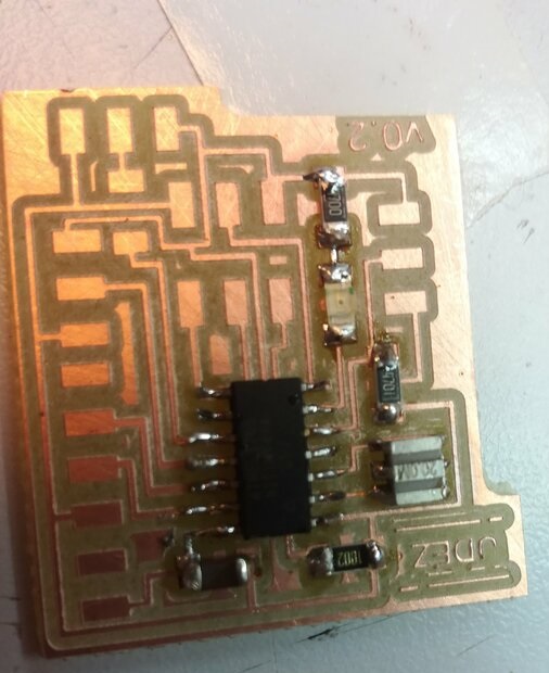
At this time I found that I forgot to connect the GND of oscillator to the GND, but it's not big mistake, I can easly fix it by adding wire.
Programming
To programm the board, I used my FabISP, and I powered my board from the FTDI (Board need to be alimented from another way than the fabisp).
First try with my board
For the first try, I want just to test if the board works and if I can communicate correctly with it, So I tested the code of week 09. I have a serious problem with timer, so I find an error in my circuit board, I didn't connect the resonator to the ground, so I try to connect it with one wire, but for now I don't have any result.
However, I find a way to get some results (not perfect, but it's enought to be able to test :p). The tricks, is to set high frequence to the communication and listen in small frequency the result. This was really bad solution, I was happy to find how to fix clock troubles (see Embedded programming week).
Then using the example of one wire library, and using serialsoftware, I tried to have values of temperatures, you can see bellow, the commented code:
#include <Arduino.h>
#include <SoftwareSerial.h>
#include <OneWire.h>
#include <DallasTemperature.h>

const int ledPin =  7;      // the number of the LED pin

#define rxPin 0
#define txPin 1

SoftwareSerial mySerial(rxPin,txPin);

// Data wire is plugged into pin 2 on the Arduino
#define ONE_WIRE_BUS 2
// Setup a oneWire instance to communicate with any OneWire devices (not just Maxim/Dallas temperature ICs)
OneWire oneWire(ONE_WIRE_BUS);
// Pass our oneWire reference to Dallas Temperature.
DallasTemperature sensors(&oneWire);


void setup() {
 // initialize the LED pin as an output:
 pinMode(ledPin, OUTPUT);
 // initialize the pushbutton pin as an input:
  mySerial.begin(10000000);
  mySerial.println(F("Initializing..."));
  sensors.begin();
}

void loop() {
   digitalWrite(ledPin, HIGH);

  sensors.requestTemperatures();
  mySerial.print(F("Temperature is: "));
  mySerial.println(sensors.getTempCByIndex(0)); // Why "byIndex"? You can have more than one IC on the same bus. 0 refers to the first IC on the wire
  //Update value every 1 sec.
  delay(500);
 }
The error
I couldn't compile the code for the attiny44, they are no enought size in the microcontroller, so the output error looks like that :

I tried to remove Software serial, and the build was done, but it was totally unnecessary, because I need serial communication to debug. So I need to find an alternative maybe.
Sketch uses 2702 bytes (65%) of program storage space. Maximum is 4096 bytes.
Global variables use 56 bytes (21%) of dynamic memory, leaving 200 bytes for local variables. Maximum is 256 bytes.
Also, I tried to remove the dallas library, to see how many space I will win. I start from this example. But finally the compiling was not done, the sketch is too big.
Sketch uses 5782 bytes (141%) of program storage space. Maximum is 4096 bytes.

Global variables use 307 bytes (119%) of dynamic memory, leaving -51 bytes for local variables. Maximum is 256 bytes.
Sketch too big; see http://www.arduino.cc/en/Guide/Troubleshooting#size for tips on reducing it.
Error compiling for board ATtiny24/44/84.
Code it in pure C to solve the error
To solve this error, I have two options, change the attiny44, or optimize my code to reduce the size of code (so not use Arduino Framework with software serial). The first one is easy to do, but it's not really a solution, I can't do that every day, and I think my program is not so complex so it will be a good thing to know how to make real C for embedded programming during the fabacademy.
So because, I think PlatformIO, is better for pure C developpement, I choose it, to be able define all the specific parameter that I want.
Because I missed the connexion between the resonator GND and the GND, I can't activate the 20Mhz clock. So I lfuse 0x42 to set the internal clock to 8Mhz. When the clock is set to this value the baudrate 115200 will not work, you need to down at 9600 to be sure, that it will work.
Then after test neil ok in board, I separate the code of neil in separate file called serialneil.h, then I included in my main
So after that, the idea was to include the ds18b20 library to decode one wire protocole of the manufacturer.
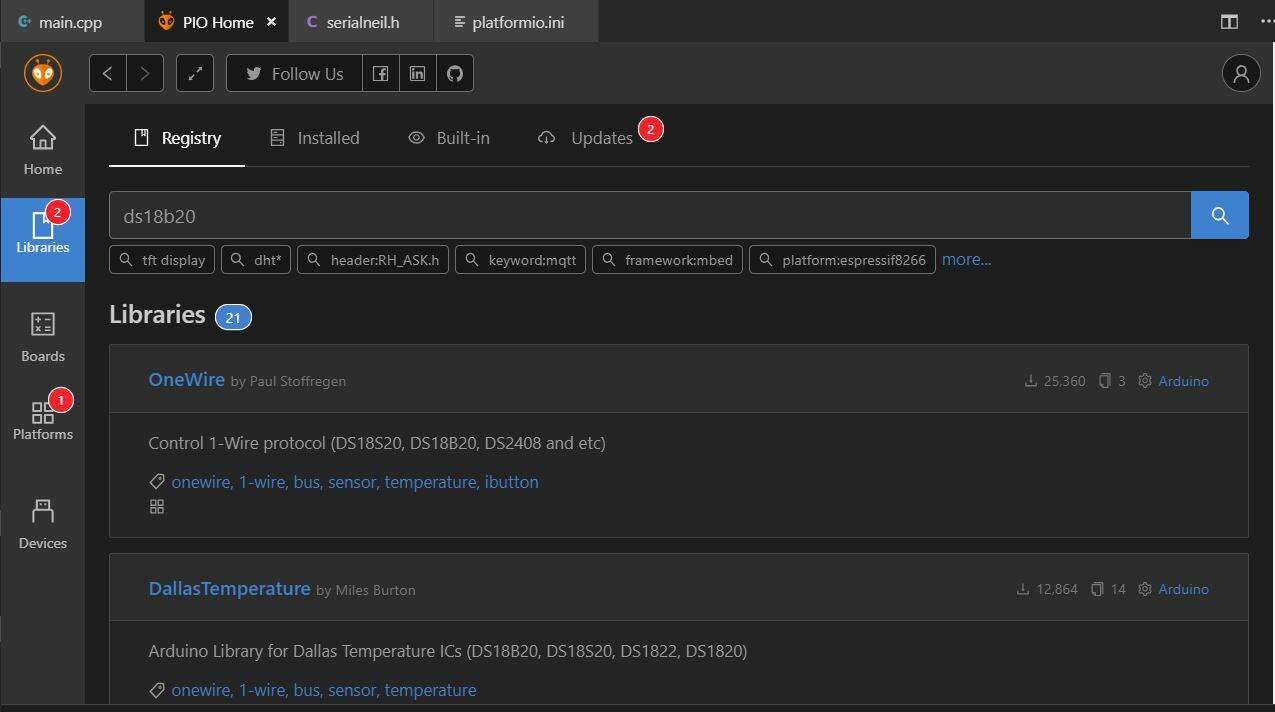
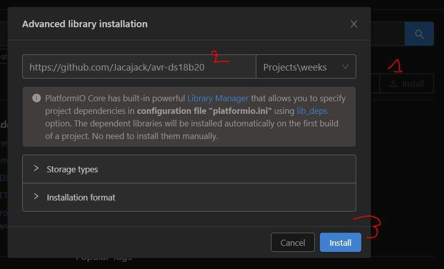
I picked the most downloaded, and try to use it, but the library requires arduino, so, I will find another one to not use arduino. So I picked this library (no dependecies with arduino), and install the dependecies in plateformIO, by giving the github url repository. But for the reason that I don't know it doesn't work.
So even, I wouldn't add Arduino dependecie, I had to add it for validate this assignments. But instead to use the serial library of arduino, I juste kipped the neil's routine. Furthermore I take function from stackoverflow to convert int into char *.
So this is the code that I used :
#include <avr/io.h>
#include <util/delay.h>
#include <avr/pgmspace.h>
#define F_CPU 8000000UL                         // internal clock set to 8 MHz
#include <stdio.h>

// needed for the ds18b20 sensor
#include <Arduino.h>
#include <OneWire.h>
#include <DallasTemperature.h>
// serial communication
#include "serialneil.h"


#define max_buffer 25

#define serial_port PORTA
#define serial_direction DDRA
#define serial_pins PINA
#define serial_pin_in (1 << PA0)
#define serial_pin_out (1 << PA1)

// picked from https://stackoverflow.com/questions/8257714/how-to-convert-an-int-to-string-in-c/23840699
char* itoa (int16_t value, char *result, int base)
{
    // check that the base if valid
    if (base < 2 || base > 36) { *result = '\0'; return result; }

    char* ptr = result, *ptr1 = result, tmp_char;
    int tmp_value;

    do {
        tmp_value = value;
        value /= base;
        *ptr++ = "zyxwvutsrqponmlkjihgfedcba9876543210123456789abcdefghijklmnopqrstuvwxyz" [35 + (tmp_value - value * base)];
    } while ( value );

    // Apply negative sign
    if (tmp_value < 0) *ptr++ = '-';
    *ptr-- = '\0';
    while (ptr1 < ptr) {
        tmp_char = *ptr;
        *ptr--= *ptr1;
        *ptr1++ = tmp_char;
    }
    return result;
}

// Data wire is plugged into pin 2 on the Arduino
#define ONE_WIRE_BUS 2
// Setup a oneWire instance to communicate with any OneWire devices (not just Maxim/Dallas temperature ICs)
OneWire oneWire(ONE_WIRE_BUS);
// Pass our oneWire reference to Dallas Temperature.
DallasTemperature sensors(&oneWire);


int main(void) {
   //
   // main
   //
   //  static char chr;
   static char buffer[max_buffer] = {0};
   //  static int index;
   int16_t temp;
   //
   // set clock divider to /1
   //
   CLKPR = (1 << CLKPCE);
   CLKPR = (0 << CLKPS3) | (0 << CLKPS2) | (0 << CLKPS1) | (0 << CLKPS0);
   //
   // initialize output pins
   //
   set(serial_port, serial_pin_out);
   output(serial_direction, serial_pin_out);
   sensors.begin();

   //
   // main loop
   //
   while (1) {
      sensors.requestTemperatures();
      // put_string(&serial_port, serial_pin_out, "Temperature is: ");
      put_string(&serial_port, serial_pin_out, itoa(sensors.getTempCByIndex(0), buffer, 10)); // Why "byIndex"? You can have more than one IC on the same bus. 0 refers to the first IC on the wire
      put_string(&serial_port, serial_pin_out, "\n\r");
      _delay_ms(100);
   }
}
Before to connect the DS18B20, I maid a test to see what value I will have without any sensor, then I saw that the code compile as well, and the serial output was by default equal to -127, then I decide to connect the DS18B20 to my board to see what's going on.
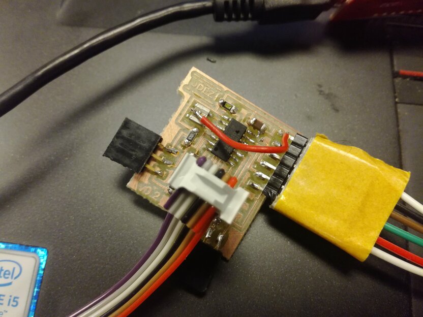
Connect the DS18B20 to the board:
- Red wire:
VCC - Yellow wire:
PB2 - Blue wire:
GND
Then to have a nice render, I decide to use the Arduino serial plotter (Ctrl+Shift+L) to make the render. To have the render in the serial monitor, I need to send the value with two special charcters (\r\n). If I would displau two line charts in the serial plotter, I need to send message like this in the serial communication {value1}\t{value2}\r\n, each value need to be separate with the special character \t.
So here you can see the video of rendering :
Files
What's next ?
- Learn more about the DS18B20 to see the best connection for the best results.
- Find component with more precision for les containers, may be I will do it myself.