5. Electronics production
The goal of this week is to make an in-circuit programmer by milling the PCB, and to program it.
PCB preparation
For this week, I choose to made the FabTinyISP of Brian.
After reading the documentation closely. I decide, to prepare a list of all the electronics stuffs and keep it in side.
Electronics stuff
- 1x ATtiny45
- 2x 1kΩ resistors
- 2x 499Ω resistors
- 2x 49Ω resistors
- 2x 3.3v zener diodes
- 1x red LED
- 1x green LED
- 1x 100nF capacitor
- 1x 2x3 pin header
Files machine preparation
I download the traces and the outline cutout to process them in mods.
Note
In our fablab, we have a Roland machine, we get caracterize it just there.
Init
Right click
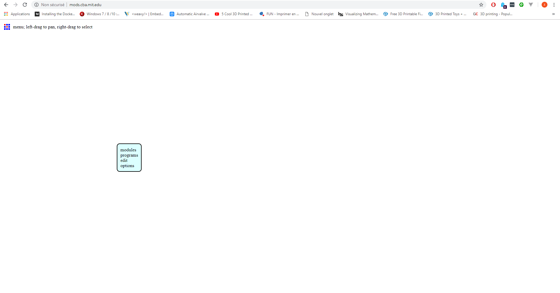
programs > open server program > machines > Roland > mill > SRM-20 > PCB
Near the
Roland SRM-20 milling machinemodule, right click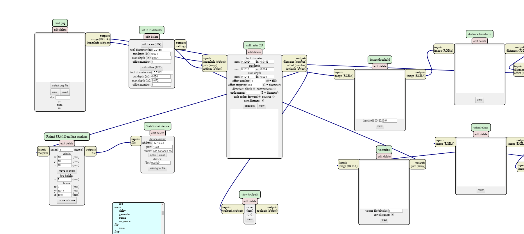
modules > open server module > file > save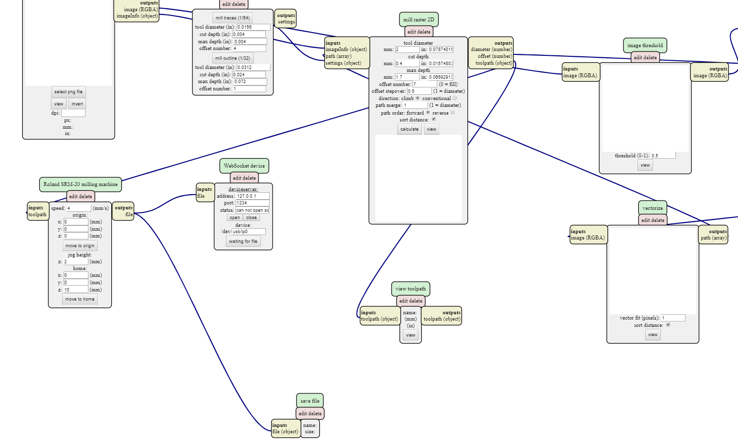
This module will help you to save the calculate file on your personal machine.
Configure
We don't have our machines in the network, so we need to configure only two modules (mill raster 2D and Roland SRM-20 milling machine) for calculating and downloading the files for the machine.
Roland SRM-20 milling machine module configuration
This module will have the same configuration for the two modes.
speed: 4 mm/sorigin:X: 0 mmY: 0 mmZ: 0 mm
jog height:Z: 2 mm
home:X: 0 mmY: 0 mmZ: 10 mm
mill raster 2D module configuration for traces
tool diameter: 0.3 mmcut depth: 0.03 mmmax depth: 0.03 mmoffset number: 7
mill raster 2D module configuration for outlines
tool diameter: 1.5 mmcut depth: 0.4 mmmax depth: 1.4 mmoffset number: 7
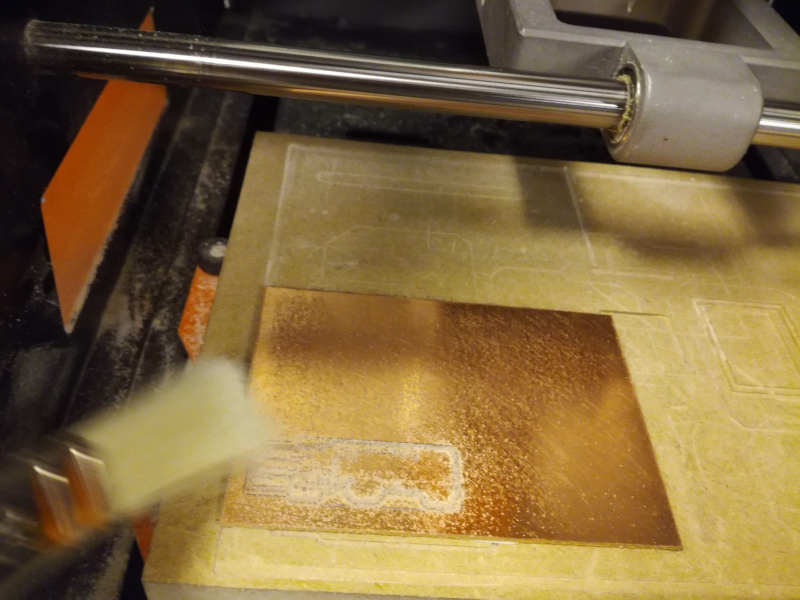
Milling PCB
Roland SRM-20 milling machine
Software
I used the V-Panel software, he's integrated in the machine.

Traces
I used the [1/8″ 30 degree engraving bit] end mil for the traces.
Outlines
I used the [1/8″ 30 degree engraving bit] end mil for the traces.
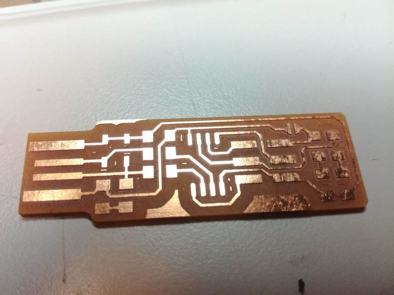
PCB fabrication
Preparation
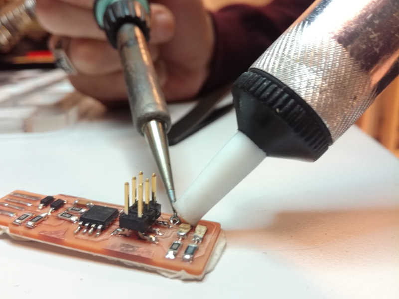
I took my box where I put all my preparation, and start to setup the soldering gun for 380°. I put my laptop near me to get easly the schematics, get on the leds and the air aspirator.
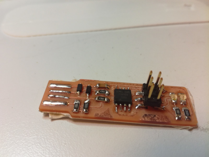
Soldering
Soldering flow
I start to solder one by one each elements:
- attiny45
- 1kΩ resistors
- 499Ω resistors
- 49Ω resistors
- 3.3v zener diodes
- 100nF capacitor
- LEDs
- 2x3 pin header
Testing
- Using the multimeter
- Connect it in usb port to see if the led work
Some mistakes
- The soldering gun was too hot, so my solder was not so shinny
- I invert the place of LEDs
- Solder the wrong resistance in the wrong place
Program the FabIsp
Now it's time to program the board to transform it to ISP 😄
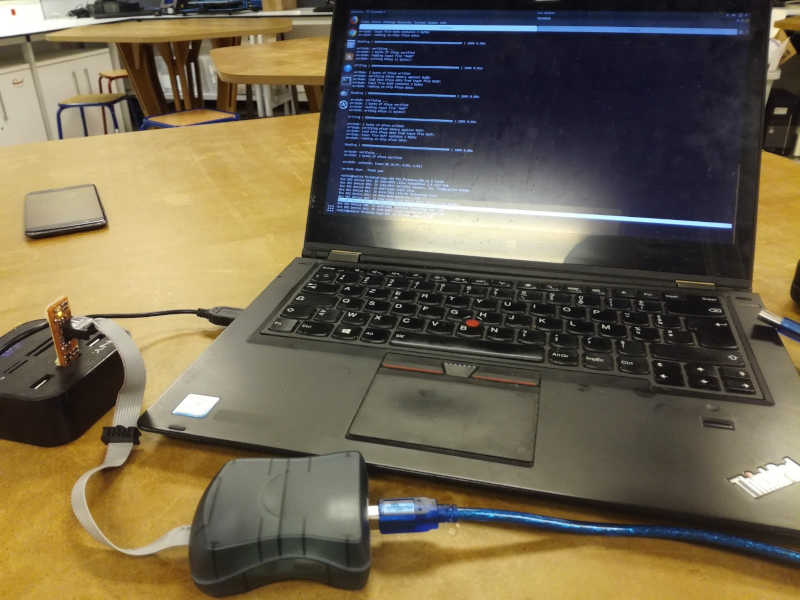
Connect the AvrISP
AvrISP is not well connected
The led is orange 🍊
AvrISP well connected
The led is green 🍏
Prepare the downloaded program for the build
I switch my laptop in ubuntu (I have dual boot, and I already have all stuff to develop in ubuntu), and I download the firmware and I extract it in my documents.
Launch the commands
Open
Makefilewith vsCode update variablePROGRAMMERtoavrisp2Run
sudo make flash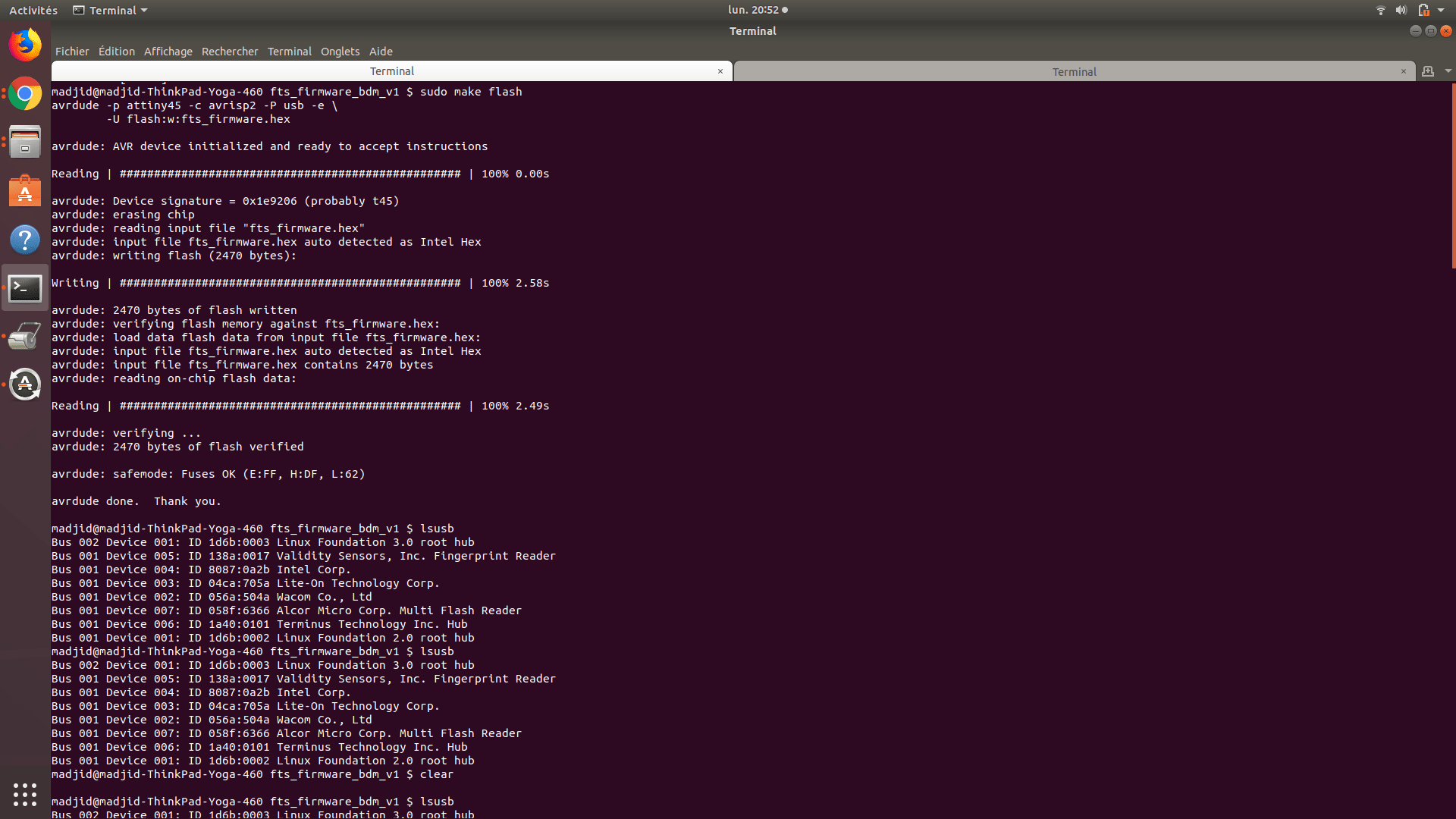
Run
sudo make fuses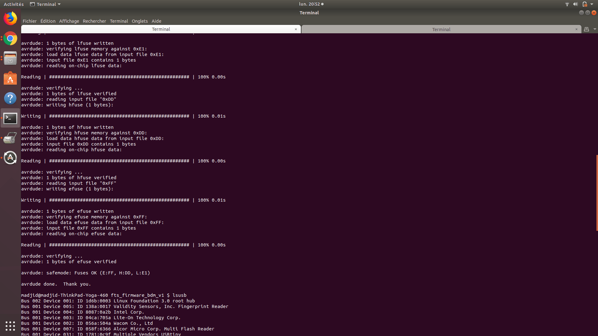
Test the usb functionnality
Run
sudo make rstdisbl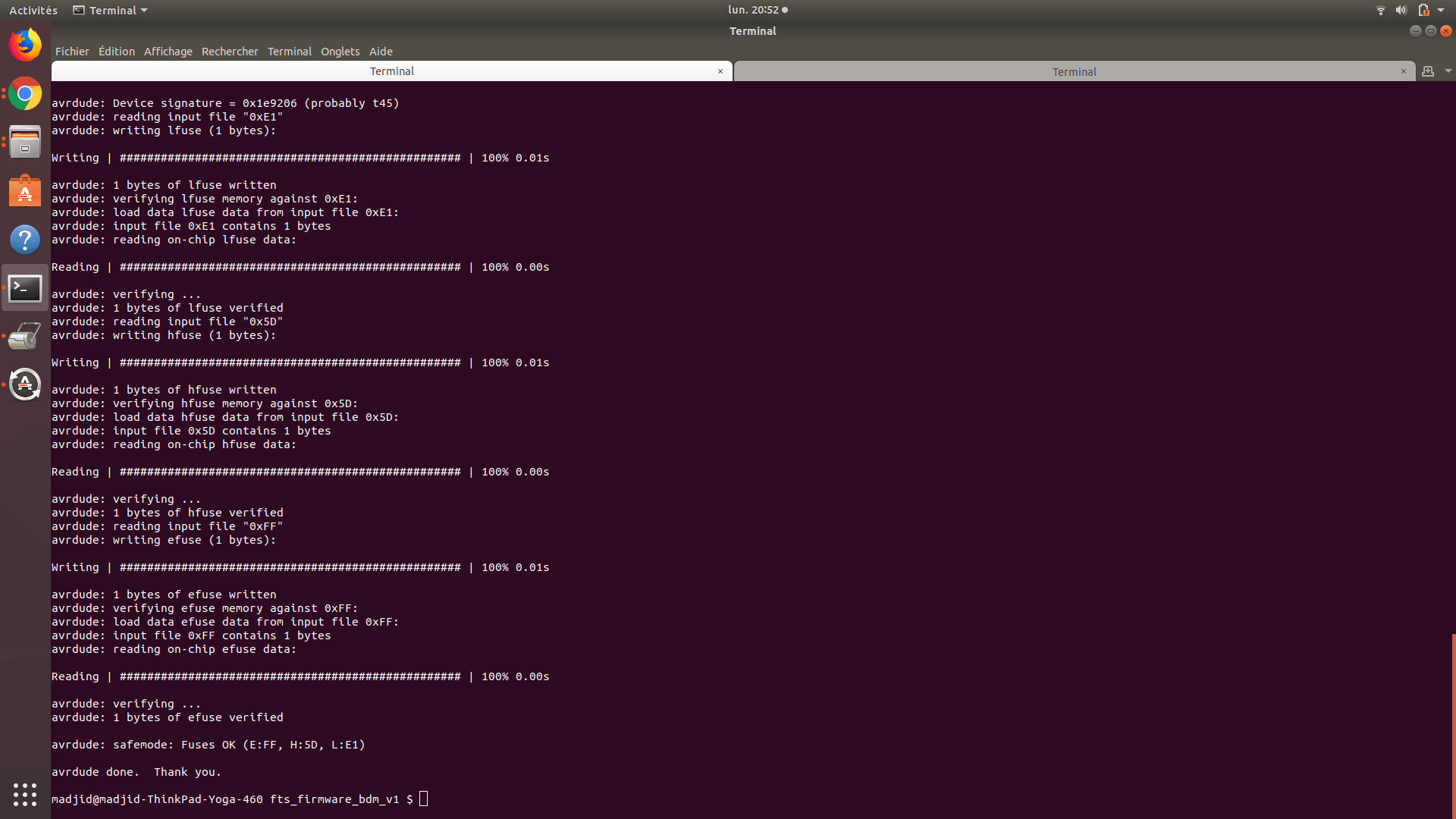
Removing the bridge on the solder jumper
Test programmer