8. Computer controlled machining
Make something big.
Table with adjustable height
For this week, I decide to choose Fusion 360 with Slicer to make the design.
Idea
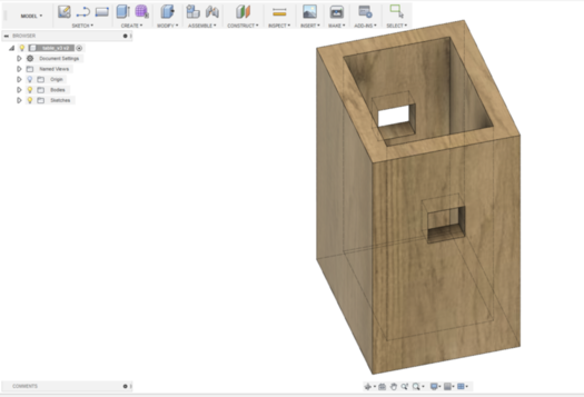
I have a small appartment and I want to make multifunctionnal table. One mode for low table and the dinner mode. Using fusion 360, I maid a design of what I had in my mind. So here you can see the render, o if you want, you can download it, just by clicking here.
'
Reality
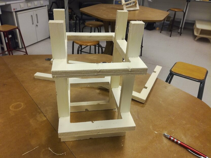
I did not make any press fit furniture or any furnitue before that and I liked the result of Slicer. So I decide to keep it simple in the first time and make just a simple low table with two feet.
Preparation
For the preparation, I decide to make one foot to start, when I'm satisfied, I will make the other foot and design the top of the table. So, using my initial design, I extract the following foot (and you can download it just by clicking here).
'
Slicer configuration
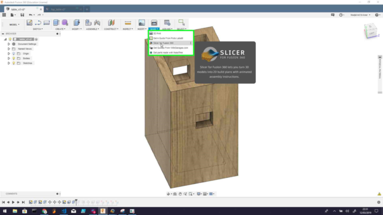
Slicer is an add-on of fusion 360, he slices and converts 3D models into 2D patterns. To install it, you need to go to the autodesk app store and download the application for the right system, launch it and restart fusion 360. After restart, in your fusion 360 model, you need to click on ADD-INS > Slicer.
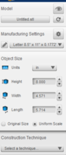
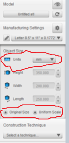
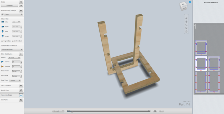
Define object size
The first task that I didi when I start, was to adjust model to his real size, by setting the right unit like you design it in Fusion. For me the defaults units are millimetters and for slicer in inchs, so I need to update it. And be sure that you have selected, Original size and Uniform Scale.
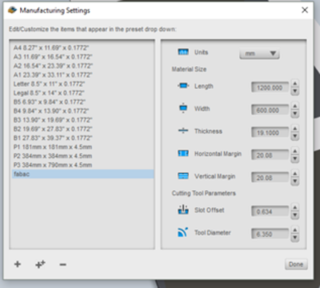
Manufacturing setting
For the manufacturing settings, the place where you define what kind on space that you have for machinin, by this way you can vizualize how many board woods, you will need have.
Construction technique
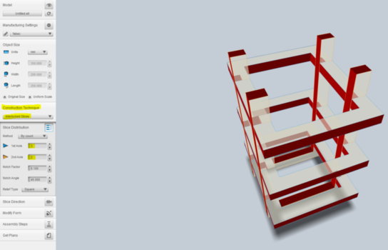
The are differents techniques to use to generate the dxf files. It's differents kind of patterns to switch from 2d to the 3d. Each of them have a possible configuration.
Interlocked Slices
Personnaly I choose the Interlocked Slices, it was the best render that I see for me.
Other techniques
Stacked slices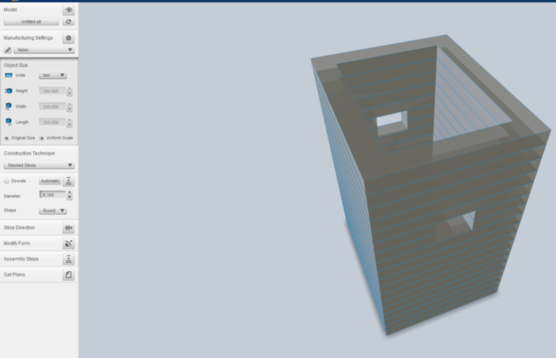
Curve...
Vcarve configuration
Fillets for angle
To facilitate, the press-fit, it recommanded to add fillets for the angles. Generally, you will choose the half of diameter of your tooling.
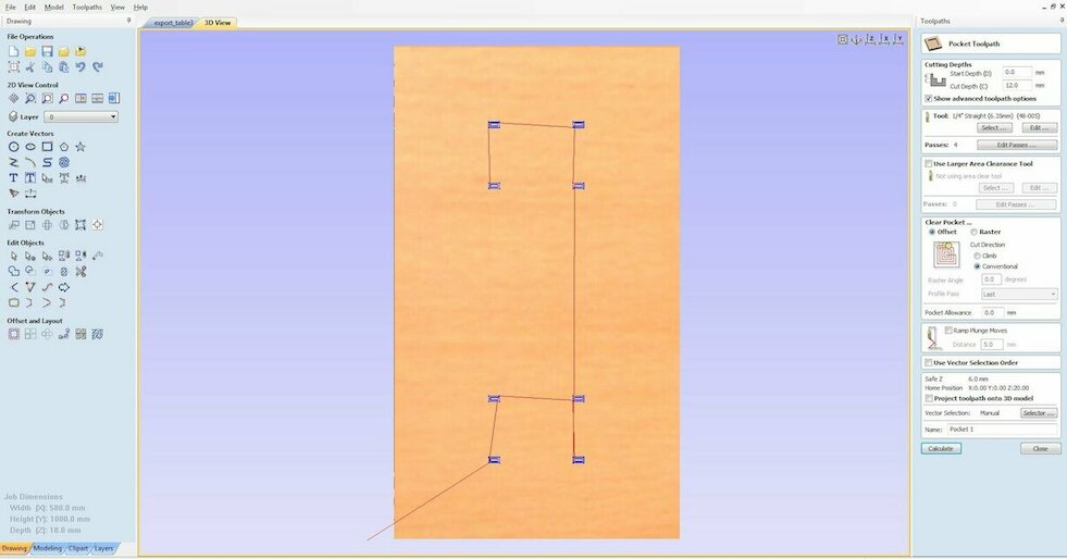
Toolpath
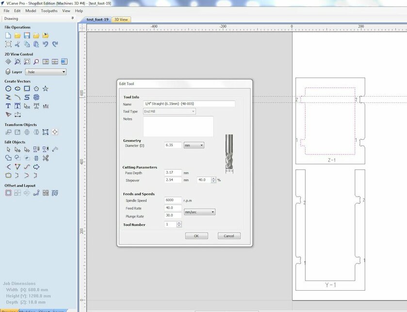
Inside/outside
I used the same parameters pour the inside and outside paths:
- End mill diameter: 6.35 mm (1/4 inch)
- Pass depth: 3 mm
- Stepover: 40%
- Spindle speed: 6000 rpm
- Feed rate: 40 mm/s
- Plunge rate: 30
And to be sure that the pieces will
Tenons
Shopbot
Before the job
- Fix your piece with 4 screws and be sure it's well fixed.
- Install the right endmill
- Define the XY relative position
- Define the z
- Turn on the vacium
- Put the wear hearing protection and the glasses
During the job
- Keep the stop button with you
- Don't move outside of the room (except if the are a fire)
- Check with your eyes if it's ok but don't touch with your arm
After the job
- Turn off the ventilator
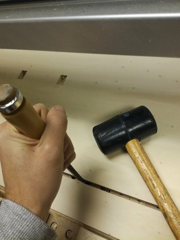
- Remove the tenons from pieces
- Clean the surface
Work process
In the first time I export all the designs of my table in slicer, but it was to much for what I want.
The surface was not plane, so to reduce the wood, I decided to design with slicer just the feet, and after I will design the top of my table.
Make the design in Fusion 360
Export the design in Slicer
Define the parameter in the slicer (see the slicer configuration part)
See the tutorial of how to build it
Export it as DXF
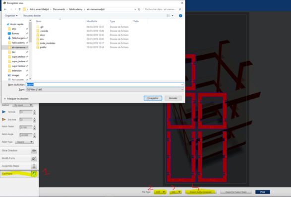
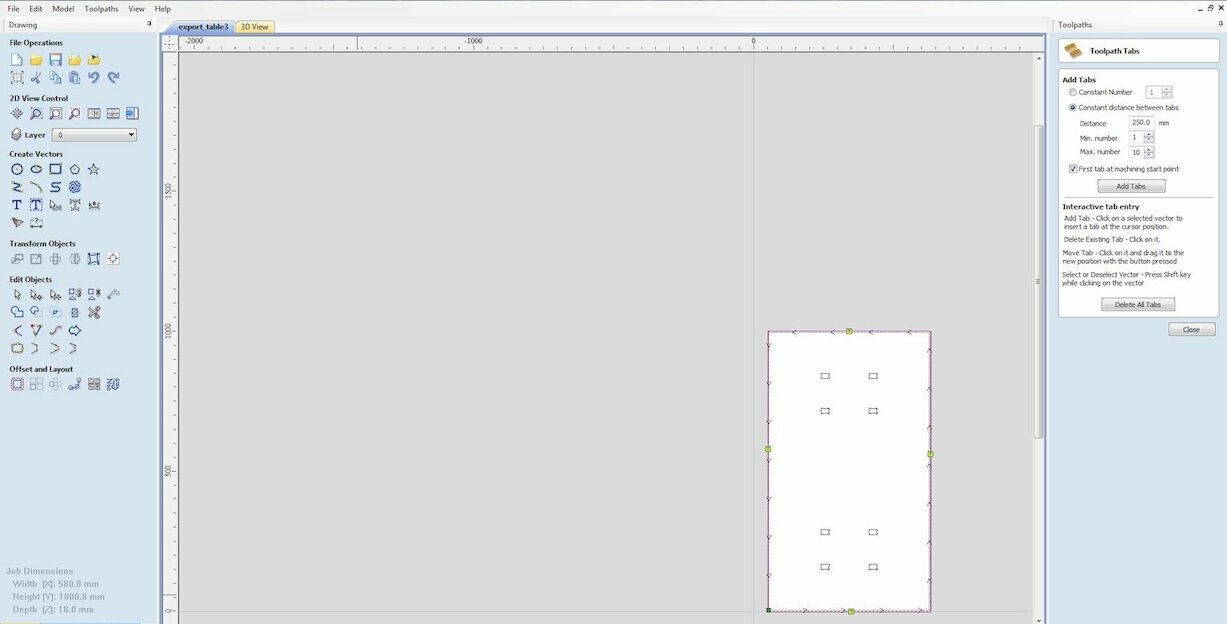
Import the files in Vcarve pro
In Vcarve add
dog bones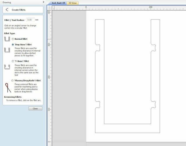
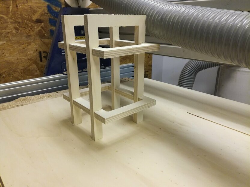
Test just for two pieces to see how it feet
The test was a success in the failure. My two pieces was hard to join. So I go to the slicers settings to update the tolerances.
Let's make it
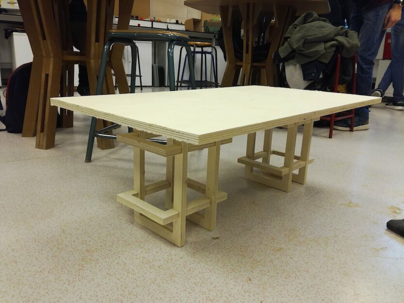
The foot is great, as I expected, I like the result so, I will maid the other one.
Top of the table
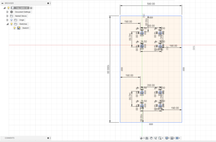
Design
Fusion 360
I knew the dimensions the holes by my first design, but to be sure, I take some real mesure with an analogic multimilimeter. Here you can download the exported dxf file from fusion 360.
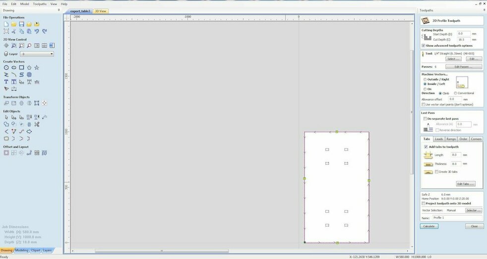
Vcarve
Like I explain in the top, I used filets in the angles to facilitate the press fit and cut the out side.
Proccess manufacturing
For sure, you need also to make all the preparation steps for the shopbot
Make the hole just for one foot
Test if it's pressfit
Keep the XYZ referential and launch all the process
Remove all the tenons
Fix the foot to see the results
Wood post processing
Remove all the unnecessary wood splinters
Sand the surface
Start by 12 and after reduce until you are satisfied by the result.
Paint if you want
Files
What's next ?
- Make new foot design in adequation of the fist idea
- Try to use some epoxy resine in the top of the table
- Paint it