15. Mechanical design
April 30
Assignment
- design a machine that includes mechanism+actuation+automation
- build the mechanical parts and operate it manually
- document the group project and your individual contribution
Machine Design 2019 from António on Vimeo.
Summary
The project is a photogrametry scanner controled by two stepper bipolar motors, where the camera is connected to a raspberry pi development board. The team as four members, divided in four areas: Organization and Lidership, Electronics, Programing and CAD.
We did change the planning according to the team members schedule. So, we start with the electronics and ended up with the assembly.
By the end of this week schedule we didn’t have the electronics ready nor the complete software prepared. Everything was retarded by the milling and the soldering issues. We lost a lot of time debugging until we decided to restart a new board. This was the first time I soldered a atmega328. Its really important to use 0.3 mm flat bits.
We have also delays directly related with the board schema design. We started by this one EAGLE board but adapted it to two steppers. After same work we decided to redo all of it from the scratch. Since its a complexe board for me I follow the Luis Carvão work.
All the EAGLE files can be found here and here. The CAD files are here
Todo
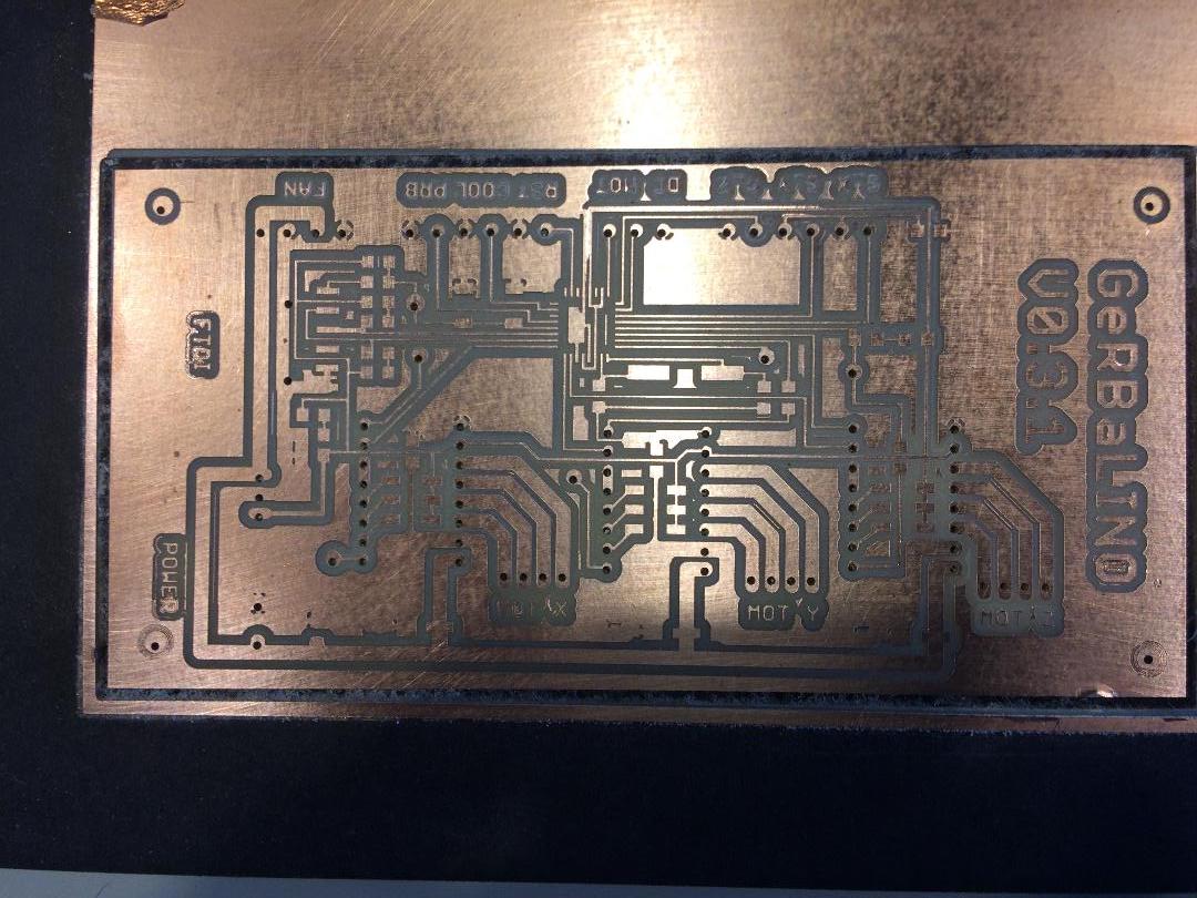
- Gerbalino board with two motors
- Running Gerbalino with sucess
Research
Prior to this week, the team did same meetings (including Filipe) already where we talk about this important work group.
After same research we found this project very challenging, a scanner: you can see it in this video. So, after same discussion, we are more close to this similar project from Make Munich 2019 fair.
Project
So, the project is a photogrametry scanner controled by two stepper bipolar motors, where the camera is connected to a raspberry pi development board.
Roles
| Team lider | Luís Carvão, LC |
|---|---|
| Programming and camera setting | Mónica Pedro, MP |
| 3D design and production | André Rocha, AR |
| Electronics production | António Gonçalves, AG |
Info
The team changed because Filipe became a father, so Luis Carvão took his place for just two weeks: the complete team is for now: Luis Carvão (LC), Monica Pedro (MP), André Rocha (AR) and me.
Each member will document the project on there sites:
- LC (lider) - Project site here and this is the plan agreeded:
- MP - http://fabacademy.org/2019/labs/fct/students/monicapaula-costapedro/02/mechanical.htm
- AR - http://fabacademy.org/2019/labs/fct/students/andre-rocha/w15.html
Planning
| Subject | work | # work hours | date | responsable |
|---|---|---|---|---|
| Programing | Bradboarding, testing the Opensan code | 16 | May, 2nd | MP, LC |
| CAD | Machine variables and draft; Openscan code | 14 | May, 3nd | MP AR LC |
| CAD, code and Electronics | milling, cad designing and coding | 12 | May, 4 | AG LC |
| Production | Electronics soldering, PCB debug, uploading the code | 12 | May 6 | AR AG LC |
| Sate of the art | meeting | May 7 | Team | |
| Production | Milling the CAD parts | May, 17th | ||
| CAD | Assemblying | May 18th | Team | |
| Docs | Documenting | May 19th | MP AR AG | |
| Production | Debugging | May 20th | Team | |
| Presentation | Filming and editing | May 21th | Team | |
| Presentation | Presenting the project to the world | May 22 | Team |
Material
- Atmega328, http://ww1.microchip.com/downloads/en/DeviceDoc/Atmel-7810-Automotive-Microcontrollers-ATmega328P_Datasheet.pdf
- 1A LOW DROPOUT POSITIVE REGULATOR - http://www.farnell.com/datasheets/1769101.pdf
- MOTOR DRIVER - DRV8880 carrier - http://www.ti.com/lit/ds/symlink/drv8880.pdf
- 4 x Led
- 4 x Resistors
- 2 x Capacitors
- 6 x terminals
- 1 x FTDI header
- 2 x Headers
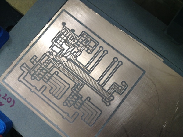
Electronics Production
The PCB, in the first we will be this one available here, at github of Humans That Make, Luis Carvão project.
At first I started to understand the PCB schematics and board layout. Then I did the first milling and didn’t went well. The board was milled only in a few places. Solution: I did follow the procedure I documented in the prior weeks “Electronics Production”, but some how I interchanged two steps, so things went wrong.
The second issue that I have to overcame was the loss of the zero reference. After trying and trying again I manage to found it and end the milling.
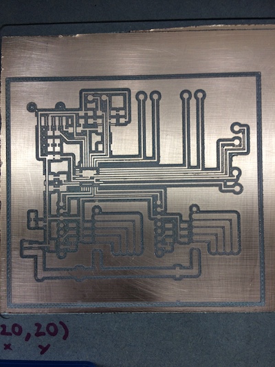
After this overcamed, I did the second milling quite well, not perfect, but close. The problem was again the drillings. I followed the same procedure documented here to solve the issue of the Eagle excellon “Trailling Zeros” that Flatcam is not abble to understand if we don’t write the wright code (see week 12).
Note
For the drilling of the Gerbalino PCB there is a need to adjust the Eagle file to the Flatcam. I have done it in week 13 for the drilling.
This is because Eagle uses Trailing Zeros in its Excellon number format but does not properly report this format in the Excellon file. To tell FlatCAM to use this format by default do this: - Open the comand line in the menu, selecting Tool and clicking on the command line; - It will open a window at the bottom; - Write: get_sys excellon_zeros, it will show a message L; - optional: if you want to check type ****set_sys excellon_zeros T**** to T, it will show a message OK; - After this open the excellon file related to the drills.
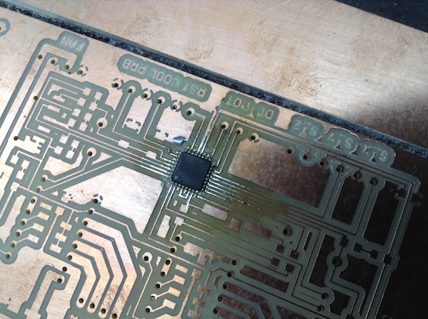
Soldering the atmega328: big issue!!! We start by spreading over the atmega soldering pads solder flux. Then put solder on each pad and spread it so that there is no “high hill” of solder, in order to make the solder as flat as possible.
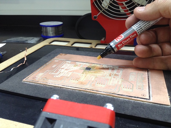
If there is same climb of solder, use of desoldering wire to spread of the solder on the routes.
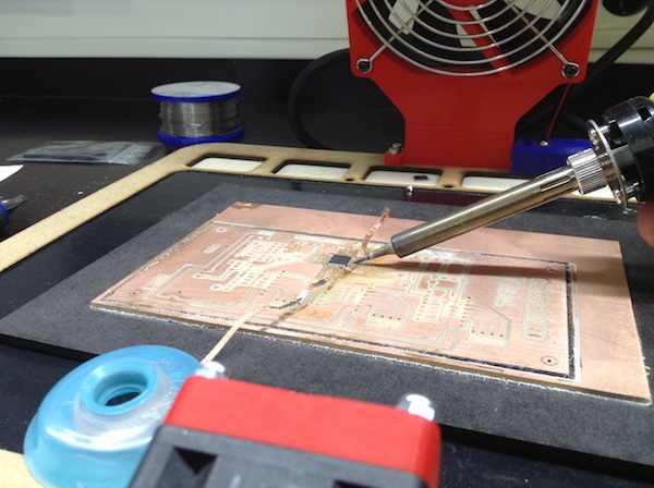
Carefully put the microcontroller over the pads with solder. Adjust it to fit over the pads. Then use the gun to finnished the soldering. Touch it to check if it is soldered.
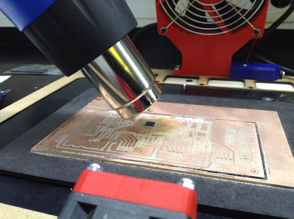
Done with the precious help of Luis Carvão.
Info
This gerbalino is the B plan.
After the two first days of work, the project changed since we found out that the machine design that we start of was not fitted to bigger objects. So we decided to use a machine with two degrees of freedom: the plate will turn around the Z AXIS 360 degrees, while around the X AXIS will just do from -30º to 30 degrees in order to be possible to scan under the objects.
It will have two endstops in the BETA angle and a magnetic reed switch to detect the ZERO reference BETA angle.
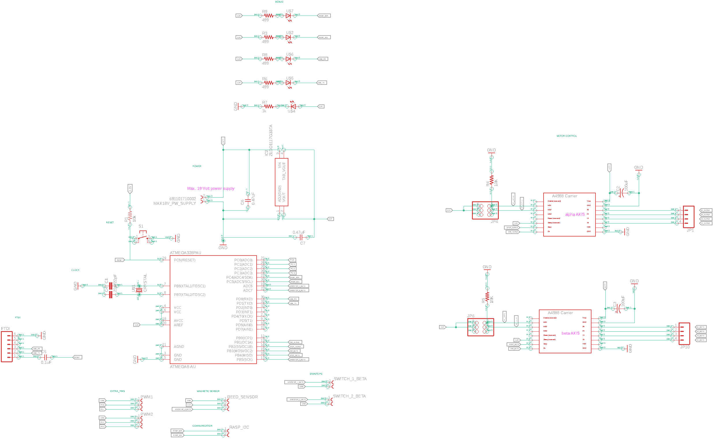
For the power supply, we decided to keep the 18 V for the steppers. Since we are using the raspberry pi, and it will comunication by I2C with the atmega328, there is a need to have 3.3 V on board. The raspberry pi 3 ARM microprocessor runs at 3.3 V (see page 13 of the datasheet). The regulator is the ZLDO1117, a 1A LOW DROPOUT POSITIVE REGULATOR AND ADJUSTABLE OUTPUTS.
The schematics for this regulator are available at the first page of the datasheet: it shows two capacitors and the pins description on page 2. The minimum values used there for this circuit design are 4.7 \micro F. Regulator can run up to 18 Volt.
For the DRV8880 pins we follow the schema on page 1 the datasheet and this Luis Carvão gerbalino reference.
The raspberry pins for I2C comunication are available here.
For the A Plan, the PCB eletronics resume is:
| Hardware | Description | pins associated | Board name |
|---|---|---|---|
| Two bipolar motors NEMA 17 | Controlling two angles, /alpha and /beta | 2 x 4 pins | 1Aa 1Ba 2Aa 2Ba 1Ab 1Bb 2Ab 2Bb |
| DRV8880 | Controlling two steppers | 2 x 4 pins | 1Aa 1Ba 2Aa 2Ba 1Ab 1Bb 2Ab 2Bb |
| Atmel328 | Motor control and comunication | 4 pins | STEPa, DIRa, STEPb, DIRb |
| Reed magnetic switch | (0,0) beta angle reference | 3 pins | |
| I^2C | Communication with RASP PI | 2 X pin | |
| LED | TX, RX, SCL, SCK | ||
| RESET button | |||
| 3.3 V regulator | |||
| Capacitores | Tackling the ripple issues | 4.7 \mu F, datasheet p.7 | |
| FTDI | FTDI, Future Technology Devices International | ||
| Two extra PWM pins |
Next stop: PCB design!!!
During the schema construction the major issue was about to find the proper PCB’s footprint for each part. We found really helpfull this SamcSys/autodesk eagle plugin library: instructions available here.
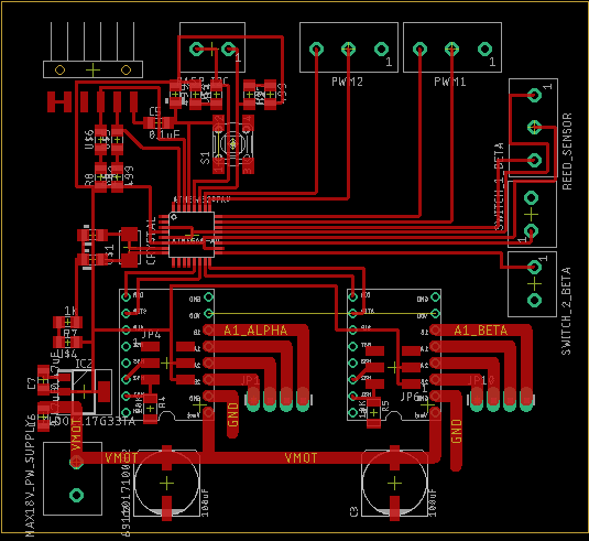
For the Board, I have the help of Luis Carvão: he did all the board and I followed what he was doing. The major strategies were:
- Connect GND and VCC in the end of the design;
- Organize the parts looking at the connections to the microcontroller;
- Make the Ratsnest at the end;
- At the end, seek for missing routes;
- Go to DRC, at the EAGLE menu, and click on clearance: we use 0.39 mm;
Info
For the Ratsnest I did this: Make a polygon arround the PCB board; give it a name: in this case GND; on the left menu, click on Ratsnest.
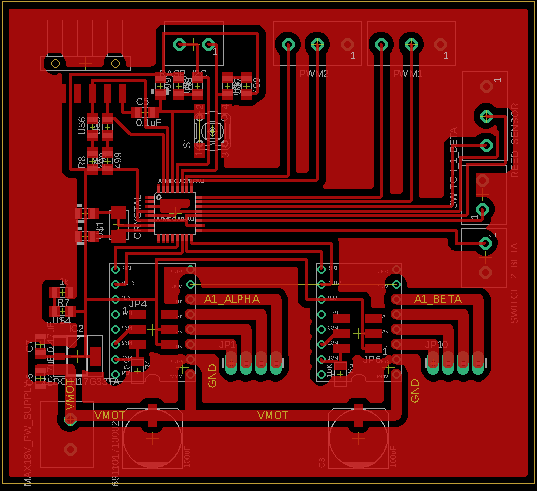
Milling the A plan PCB.
Info
At this point we make a breakthrough about the use of the milling Carvey adding two simple procedures: 1. If there is an error in a file and you have to remake the file on flatcam and return it to the chillipepr you have to change the name of it for the autolevell to be taking in account; 2. We define the reference of the board to be milled from the reference of the machine;
Drilling
Info
Very important do set the zero out in relative to the machine zero reference.
Flat Cam settings: cut Z: -2 mm; travel: 2 mm; Feed rate: 40 mm/min; no tool change; spindle: 8000 rpm;
The result for now…
To be continued at next Machine Design, the 17th week: debugging and soldering… and debuging again.