6. 3D Scanning and printing
February 20
Assignments
group assignment: test the design rules for your 3D printer(s); individual assignment (understand the limitations): - design and 3D print an object (small, few cm3, limited by printer time) that could not be made subtractively; - 3D scan an object (extra credit: optionally print it)

Summary
We test five different 3D printers with this Thingiverse design downloaded from crtvL(https://www.thingiverse.com/thing:704409/files) user, just to study the settings: angles, mininum to separate, corners, screws, and more (see table below).
I can conclude that all the machines shrink the holes and the tolerance is very diferent, in the interval 0.08 to 0,60 mm for the diameter parameter.
For the XYZ measurement, there is no homogeneous behavior, same tend to shrink others tend to increase the dimension.
For the minimum separation, two of them get close to 0.2 mm. But in all, 0.3 was ok.
Curves were all ok, as well as the shapes, bridges and angles. Nut M4 was ok with all the machines except on one.
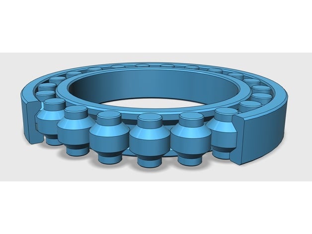
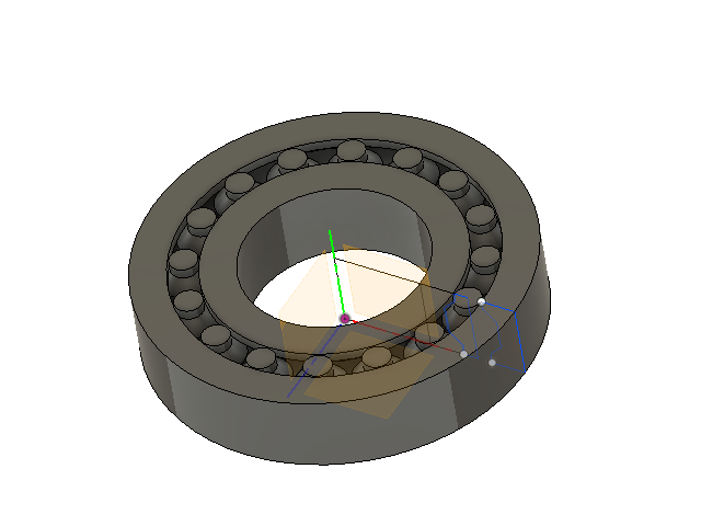
I made a bearing design for the second assignment with fusion based on this 3D bearing on thingiverse of Brian Brocken. Its really dificult to get the right equilibrium between the number of rollers and the Tolerance_1. I use this render as a starting point.
The bearing parameters settings were made in FUSION 360, in order to control the design to function properly. The parameters I used are described bellow. I also used constraits and found out that, the number of rollers and the roller inner radius, are crucial for the correct functioning of the bearing. Is seems that the 0.20 mm is ok for the 16 rollers inside the bearing. Lets see.
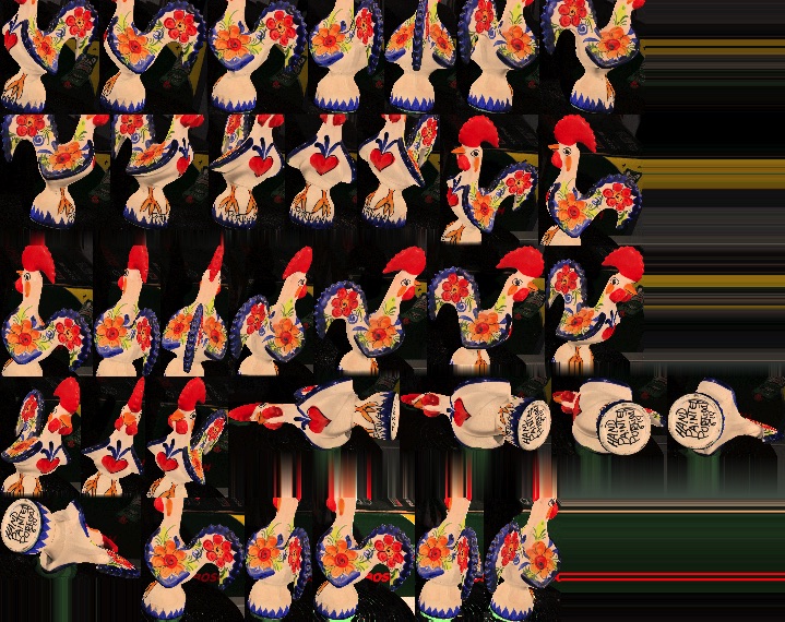
For the scan we scanned a roaster with three diferent devices: camera, HP 3D scan and iSense (see links at the bottom). The best was the one that we took more time and were more carefull to cover all the object with scanning. We did this at at “Humans that Make” (a special thanks to Luís Carvão). The 3D printed results were satisfactory.
Todo
- finish the bearing
- Print the Roaster
- Compare finnaly the bearings
- Test the Ultimaker 2+
- Print bearing (version 6)
- Types of 3D files
- Printers pictures
- Post printing processing procedure and technics
- Link PLA and resins
- final conlusion of the bearing trials
Work done
3D settings
In the group assignment, we compare the settings of six 3D printers, three of them portuguese, one Dutch and one Spanish .
We will use natural 1.75 mm PLA filament from a portuguese company REPRAP.
The 3D design to be printed is this one, by CRTLV user, at Thingiverse.
We are going to print with the same standard profile settings as possible:
Settings
- layer weight: 0.2 mm
- Wall thickness: 1 mm
- Top/bottom thickness: 1 mm
- Infill: 5 %
- retraction: 4.5 mm ; 45 mm/s
- Velocity: 60 mmm/s;
- cooling: enabled
- Temperature: 210 ºC;
Results

Important Note: this is not a 3D printer ranking! Its only to see which, available at our workshops, is best calibrated and what to do to better calibrate them.
| Printer | Design | beeTheFirst | Hephestos2 | Blocks ZERO | Ultimaker | Blocks ONE | Ender3 |
|---|---|---|---|---|---|---|---|
| ZXY measures (baseplate) | 4x50x50mm | 4.29x50.31x50.10 | 3.91x50.09x50.12 | 3.93x49.91x40.96 | 4.27x49.93x49.67 | 4.26x50.16x50.06 | 4.25x49.90x50.23 |
| Inclination | (25-45 degrees) | ok | ok | ok | ok | ok | ok |
| Curves | wave, half sphere | ok | ok | ok | ok | ok | ok |
| Angle (letters) | CTRL V | medium | ok | ok | ok | ok | ok |
| Bridges | ⅔/⅘/6/⅞/9mm | medium | ok | ok | ok | medium | ok |
| Diameter (3 holes) | ¾/5mm | 2.75/3.74/4.67 | 2.81/3.81/4.69 | 2.58/3.67/4.61 | 2.40/3.37/4.30 | 2.58/3.63/4.58 | 2.92/3.91/4.78 |
| Distance between walls | 0.1/0.2/0.3/0.4/0.5mm | >0.3 | >0.3 | >0.2 | >0.3 | >0.4 | >0.2 |
| minimum separation | distinguishable with a cell phone zooming | 0.3 | 0.3 | 0.2 | 0.3 | 0.4 | 0.2 |
| Nuts | M4 | Really Tight | Tight | Tight | doesn’t fit | Tight | Tight |
note: all was measured with:
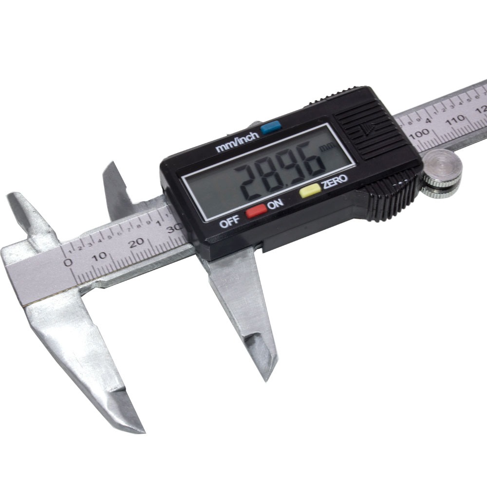
note: ok means that the printing was good note: all the printers were within the 0.4 mm normal tolerance
printers


3D Bearing
I did the design based on this project and divided the design in five parameters and several constraints devided on parallel and equal options at Fusion360. There are other ideas about for the bearing. This is important because I want to use a 3D printed bearing for the rudder of the boat.
About the 3D design, I just made a sketch on FUSION360:
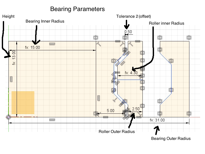
And then, the tool revolve, three times: for the roller, the outside and inside wall of the bearing.
This are the first results. One short on rollers the other just in the edge of the 3D printer where they where glue together.
Comparing the parameters (all in milimeters except the number of rollers). The diferent between versions 1, 2 and 3 is only the number of rollers and the tolerance. I want to evaluate the bearing quality function and the tolerance of the 3D printer.
This picture shows all the testing and fine tunning. The yellows are aligh by version 1, 2 and 3. The PLA natural ones are version 4 and 5. I will print version 6, 0.2 mm tolerance: does it work?

| Bearing | Version 1 | Version 2 | Version 3 | Version 4 | Version 5 | version 6 | version 7 |
|---|---|---|---|---|---|---|---|
| Outer Radius | 31 | 31 | 31 | 31 | 31 | 31 | 31 |
| Inner Radius | 15 | 15 | 15 | 15 | 15 | 15 | 15 |
| Height | 13 | 13 | 13 | 13 | 13 | 13 | 13 |
| Upper Roller Radius | 2.5 | 2.5 | 2.5 | 2.238 [1] | 2.275 [1] | 2.275 [1] | 2.275 |
| Inner Roller Radius | 4.3 | 4.3 | 4.3 | 4.377 [1] | 4.432 [1] | 4.416 [1] | 4.409 |
| Number of rollers | 14 | 15 | 16 | 16 | 16 | 16 | 16 |
| Distance between the Roller centers [1] | 10.236 | 9.564 | 8.974 | 9.067 | 9.081 | 9.081 | 9.081 |
| Tolerance_1 [2] | 1.636 | 0,964 | 0.374 | 0.313 | 0.217 | 0.25 | 0.264 |
| Tolerance_2 [3] | 0.5 | 0.5 | 0.5 | 0.25 | 0.15 | 0.20 | 0.22 |
| Evaluation | no | no | no, one roller down, no space to add another roller. Redesign | Not satisfactory, one/two rollers roll in the X and Y directions | no | no | yes, version 8 |
- [1] - Measured by the Fusion360 cad software
- [2] - Minimal distance between the rollers
- [3] - Offset, Minimum distance between the roller edge and the inner edge of the bearing
After version 4, this included, I change the 3D design strategy, so, I decided to draw the shape of the inner roller, offset this by the Tolerance_2, and use this offset to close the inner wall of the bearing till the inner radius of the bearing. After this I did a symmetry process to link to outter wall of the bearing.
Closer look to the inner rollers on version 7:

Conclusion for the bearing studies: the inner roler tolerance must not be the same as the outter roller tolerance:

Now, there is a need to find the math relation between the tolerances because the issue is this one: for the same tolerance the inner rollers still have a large tolerance:

Scan the Roaster
HP 3D Scan
One of the portugueses myths its about a dead roaster that help proven innocent, a man that was senteced to death.
I decided to scan one in three diferent ways: photogrametry, iSense and HP 3D Scan. For the photogrametry I use PHOTOSCAN by AGISOFT, paid educational license. The others we used the proper company brand software.
I started by HP 3D Scan, using the DAVID3 Online Instructions.
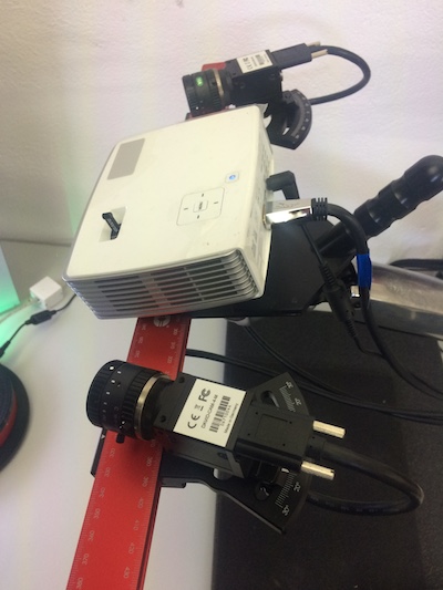
This system as several possible positions to lught up the object. It is possible to adjust the angles, the XYZ positions for small or bigger objects ( 2 m ).

We first did a calibration procedure.

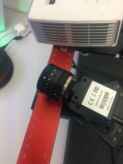
Taking care of the calibration lines, using the camera focus to adjust it and confirm it on the computer screen center focus:


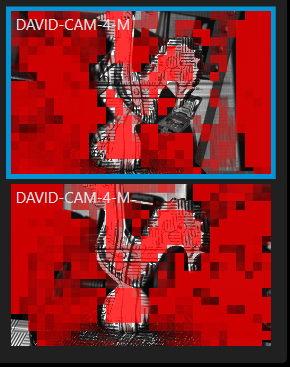
To fine tunning the exposure we need to adjust the exposure to the red functions that appear on the computer screen:

Close up. This red lines can’t be flat nor to narrow.

After the distorted lines on the 45º angle screen, the calibration means that the lines, now, they stay align:

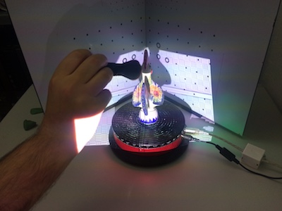
There was need to prepare the roaster with a woman face base, because it as a lot of shiny spots that could compromise the scan.
Focusing the center of the screen on the roaster was also needed and adjusting the exposure to with this focus aperture:
We push the scan button after taking car of this parameters settings:

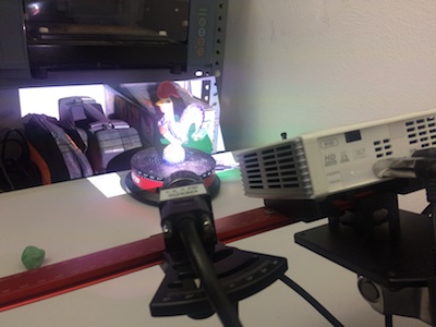
Finally, the positions of the roaster during scan:
Since the object is ultra bright the scanning didn’t have outside pixels to clear. So, we don’t need to “clean” it using the software tools. After the two scans, we selected “free” and “contact pair selection” to make the coarse registration. There were some holes. We did a third scan. After making a third group we did the final, Global fine registration: align scan:

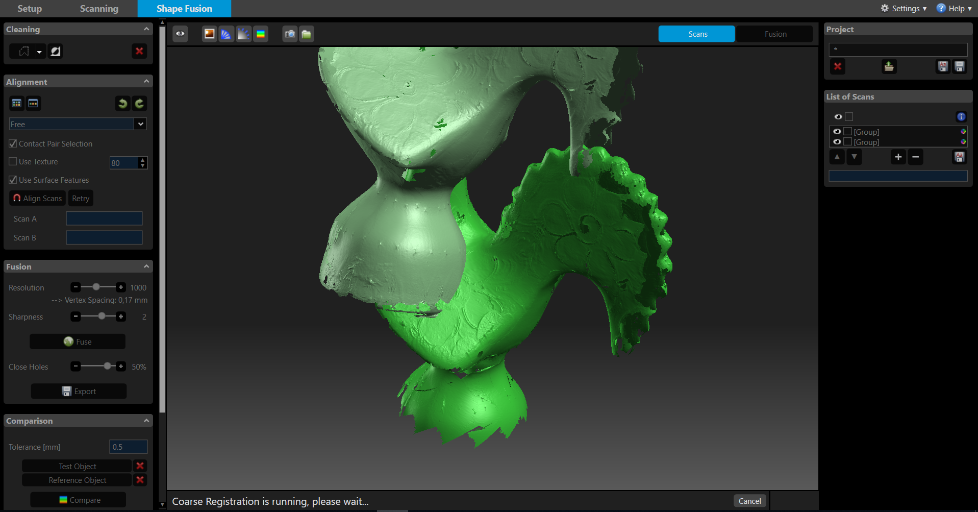
but.. there is a need for another scan because the roaster does have a dark “blue” sections, with high contrast compared to the rest of the painted structure. The scan was repeated controling the exposure, again, by adjusting the aperture of the cameras lenses and checking the computer screen to remove the red pixels:
After all of this, doing again the alignment, doing the “Global fine registration” and get this result:

Bottom line, we followed the David document. Resume:
-
- Ajusting the hardware: Screen 45 degrees (adjusting the light source on this screen)
-
- Ajusting the hardware: focus and exposure (avoid the red pixels on the computer screen)
-
- Calibrating
-
- Fine tunning the exposure
-
- Wait for the scan to end
-
- Removing the parts and the mesh
-
- Selecting the caning parcial layers, evaluating and removing, aligning.
-
- Fuse
Then we try to clean the STL file in order to be more light to work in CURA. I use meshlab tools:

And the result:

Photogrametry
I took 50 photos (this is not enough, but just to test) around the roaster, in diferent angles: azimuth and zenith. And also close ups. The angles or more or lense diferent in 10 degrees. The light was more or less uniform and the shadows were not so much.
In photogrametry: - take a lot of pictures; - avoid bright spots on the object - Avoid shadows - Use soft light
Upload them to Photoscan Agisoft.
Follow this procedure:
-
- Open the software.

-
- On the top left, click on add chunck
-
- Then add photos
-
- Follow the work flow menu, one afer the other: align photos; build dense cloud; build mesh;
NOTE: if you choose more accuracy it takes longer, but the result is better.
- 5.After the align you get this point cloud.

-
- Crop the image or select the could points to remove: just use the selection tool on the top left: there are three: rectangle selection, free and circle.
-
- Choose rotate object and continue cropping or removing the cloud points.
-
- Continue the work flow: this time choose Build dense cloud
-
- Build mesh
Note: sometimes the result is not very good, try doing the former steps with higher accuracy.
-
- Export the model
Scanning…
Roaster scanning from António on Vimeo.
The result:

iSense
iSense is very easy to use. Just set the object with a uniform light on the top of a chair and round it.


The software warns you if you move the device to fast or away from the object. After the scan, you can use this very simple menu:

Save the object in obj or stl extensions. The result:

Printing the scans
Not all of the roaster were printed. Only the two last one’s, from photogrametry, was the only one not to be printed. The best result, off course, is the analogic one. The best digital is from HP 3D Scan, but it was the one that took more time to scan, with more detail, were we spend more time. So, its not fare to compare the results:

Files
You can find here all the files.
File formats
A 3D file format store information about 3D models as plain text or binary data, refering to: - geometry: shape; - appearance: colors, texture, material type; - scene: light positions and sources, cameras and other objects; - animations: how a 3D model moves;
Not all of the 3D format files store all the information, except COLLADA
How many there are? here
| File Format extension | Name | Information | Used | Notes |
|---|---|---|---|---|
| STL | STereoLithography | 3D geometry alone by triangular mesh | 3D printing, rapid prototyping, and computer aided manufacturing | 3D Systems |
| OBJ | 3D geometry alone: triangula mesh, polygons like quadrilaterals, smooth curves and surfaces (NURBS) | 3D graphics | Open, Wavefront Technologies, can encode color and texture information: .MTL | |
| PLY | Polygon File Format | color and transparency, surface normals, texture coordinates and data confidence values | 3D scanners | more |
| DWG | storing two- and three- dimensional design data and metadata | CAD | Proprietary, Autodesk | |
| VRML | Virtual Reality Modeling Language | polygonal mesh: can store appearance | developed for the World Wide Web | pronounced vermal, succeeded by X3D |