14. Networking and communications
Assignment
individual assignment: design, build, and connect wired or wireless node(s) with network or bus addresses group assignment: send a message between two projects
Summary
For this week, since it is very important, crucial I say, for the boat project. I started to review Neils lecture, following the crucial concepts to retain and defining a new strategy for the boat electronics: use several PCB’s to avoid interference between the modules of the electronics project.
I tried several ways but just concluded one, showed on the video above: communication serial using the arduino library.
Asynchronous transfers serial comunication is only possible when you want to comunicate between only two processors.
All the files are here and at my personal google drive here.
Todo
- review Neil lecture
- Make the nRf24L01 and the BT RN4871 board proposed
- make a very basic BUS connection
- test them
- Simulate a radio/RLC/LC circuits
Neil
Reviewing Neil lecture
- Why network? Location, paralelismm, modularity and interference that define systems networks.
- A BUS its not a NETWORK: its just a line that connect all the boards while network is a wired net with topoloy
- Serial interfaces, like FTDI, FTDI, Future Technology Devices International, it uses RS 232, this “standard defines the electrical characteristics and timing of signals, the meaning of signals, and the physical size and pinout of connectors”, source: https://en.wikipedia.org/wiki/RS-232.
- In this case, RS232, there is a BUS that connects the host and the boards that are wired to the BUS in a Rx Tx line: all the boards listen to the transmit line and talks back to the Rx line.
- Other standards are RS422 and RS485;
- In the video example each board is taken Tx, Rx, GND and Vcc through the BUS;
- This Rx Tx comunication works, because on yhe Rx side each board pin connected to the Rx line can be in three states: HIGH, LOW or TRYSTATE (which means disconnected, listening)
- CODE: assign the pins; each node gets an ID;
- A BUS needs a master that tell to the clients when to talk;
- I^2C became open: https://www.eetimes.com/document.asp?doc_id=1200974#
- RS232 is assynchronous and I^2C is synchronous;
- About Synchronous and Asynchronous Data Transmission_: https://teachcomputerscience.com/synchronous-and-asynchronous/
- RS232: decide the data rate in advance;
- min. 13:40: I^2C: two pins, one is a clock the other is the data: the data is readed when the clock makes the transition;
- I^2C: used to connect processors and smart devices;
- TWI and SWI are hardware modules;
- Arduino Wire Library: https://www.arduino.cc/en/reference/wire
- I^2C advantages: talking to different devices and easy to implement;
- SPI (Serial Peripheral Interface): used for the ISP boards weven’t making.
- SPI PINS: MISO (master IN slave OUT), MOSI (master OUT slave IN), SCK (System clock), Vcc, GND, Reset
- SD memory cards: SPI; hard but usefull to implement;
- USB: same microcontrollers does have USB hardware modules;
- USB library: LUFA, implement all the diferent devices over USB hardware modules;
- LUFA: if you run this library in a USB processor it appears to the computer as a serial device that already knows about;
- V-USB library: implements USB in software: the ISP first project we did;
- V-USB: adjust the clock to the host by measuring the data rate his receiveing;
- min. 00:35: NETWORK - OSI layer means Open Systems Interconnection model and define layers of software in a network.
-
Layer Acronym Task 7 HTTP Aplication 6 SSL link to the application in the computer 5 RPC Open a connection 4 TCP, UDP Control the message sending and receiving, when to start and stop 3 IP Give an adress to a message 2 MAC The data link layer provides node-to-node data transfer 1 PHY Physical medium -
Neil course MAS.862: The Physics of Information Technology
- Source: Shannon–Hartley theorem:
C = B log_2 ( 1 + \frac{S}{N}),
where, C - Capacity (b/s); B - Bandwidth (Hz); S - average received signal power (W); N - average received noise power (W) - Online video about information theory, by David MacKay, at Cambridge University; - More data if you have wider frequencies (bigger bandwidth); more data if we have more power and less noise; - Two wires are more immune to noise; - Ethernet, 802.3, better o use the module; - SONET, the standard for optical fibers; - min 38:21: Radio, each country has its own legislation standards; - Open bands; 2.4 GHz: microwaves radiate here; loaded! - There are other ISM frequencies available;
| Specification | for | Band |
|---|---|---|
| 802.11 | WIFI | 2.4 GHz |
| 802.15 | Zigbee | 2.4 GHz |
| BlueTooth | 2.4 GHz | |
| light (LIFI) | transmiting | visible |
| Sound | comunication with modulation | audible |
| - After choosing the medium frequency, there is a need to choose how to put the message in the medium; |
| Modulation | PHYSICS | note |
|---|---|---|
| PCM | amplitude | measuring the amplitude |
| PPM | Pulses | measuring the time duration of the pulse |
| OOK | Turn on and off | |
| FSK | frequency | two frequencies as HIGH and LOW |
| BPSR | phase of the signal | two phases to be measured |
| QAM | combination of frequency, amplitude and phase | each state has many bits of information |
| OFDM | divide frequencies | |
| FHSS | Signal modulation to look random | most powerfull |
| DSSS | ||
| UWB | spread signal over all band | |
| - Channel sharing: CSMA (WIFI rooters); CDMA (cellphones); MIMO (multiple antennas) | ||
| - errors: redundancy; | ||
| - Networking: adresses and topology; EX: internet (IETF organization); | ||
| - RFC: IPv4: most important by far: specifies the internet protocol: interne datagram header: in thsi format it can goes anywhere in the world; | ||
| - Talk to the internet: needs an IP packet. | ||
| - DNS: transform fabacademy.org into the adress; | ||
| - ports: UDP takes the IP packet and gives it a port; and the port send it to the aplication; TCP, takes a big message, makes a package and check if it was received; | ||
| - HTTP: standard for webpages; implemented over TCP; | ||
| - Use sockets to send massages: see examples in js and py; | ||
| - RF: Send messages without wires; | ||
| Radio, what you need? | for | Notes |
| ------- | ------------- | --------------- |
| Oscilator | make the radio signal | |
| mixer | Modulate the signal with the data | |
| Power | Amplifier tosend it out | |
| Power | A low noise amplifier to receive the signal | |
| I/O | To measure the phase | |
| Demod | demodulated it | |
| Filter | To present the signal | |
| Antenna | design it for several proposes | Impedance (space) matching and direction |
| - Radio modules: RN4871 (BT), its a kind of processor; note: all of the vendors of debuging apps; | ||
| - BT have profiles: they can be a sensor, an headphone; | ||
| - nRf24L01, not a BT or WIFI, they just talk to each other; | ||
| - LORA: lower frequency up to km of distance rabge; | ||
| - ESP8266MOD: can use sockets and interact as a webserver or a web client; | ||
| - ESP32, its more then WIFI is a powerfull processor, it as also BT inside, but it consumes a lot of current; | ||
| - GNU radio: radio by software, getting reed of the hardware part as the processors get faster and faster; getting started |
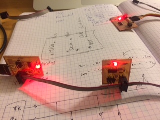
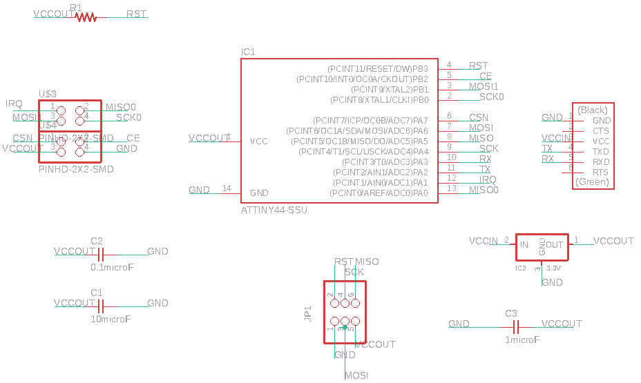
Basic bus
I plan to do the very basic BUS comunication presented by Neil at his lecture.
The schematics BUS bridge and node:
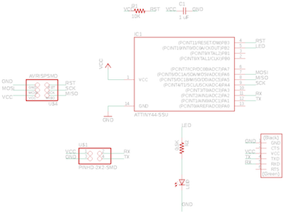
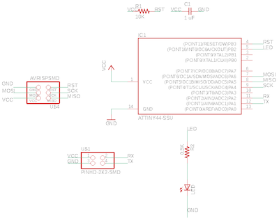
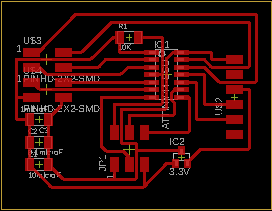
The Boards:
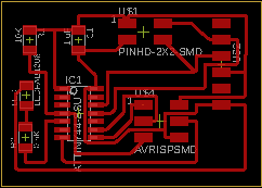
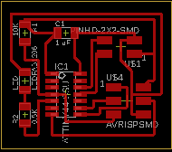
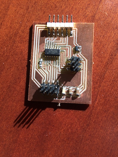
Machined boards:
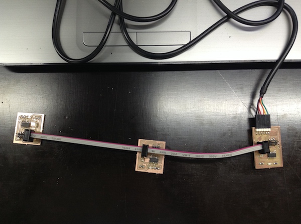
After the bootloader succeed on the BUS BRIDGE and NODE I found a problem on the second node that I have detected on the debuging step but forgot to solve on the hardware. I found a short circuit and after so many tries I didn’t manage to overcame without removing the ATtiny44. After soldering a new processor everything ok.
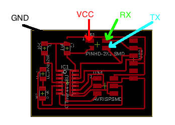
Identifying pins:
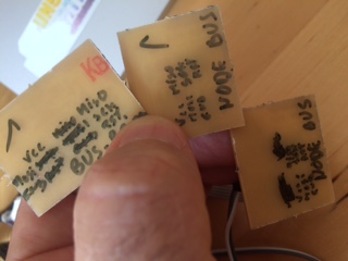
Info
Document the pins:
I did tested the boards communication and analyze closer the Neil C programming. Still found it very dificult to understand: I don’t have the mental model for it yet. So, I turn out to the web and found this simple project here.
So, starting by trying using TX RX wire were all the node were listening, googling on foruns I noticed that its no easy to do it. Out that most of the opinions were saying that it is not possible to controll the TX RX pins. Well, there is Neil code. So, in the future I will test it.
Using serial, and his serial library, convinced that it was possible to communicate between several nodes with a bridge… I found ou that’s not possible because serial is synchronous, so just two processors.
Read
Making same readings at sparkfun: “…in general, each can be separated into one of two categories: parallel or serial…
Parallel interfaces transfer multiple bits at the same time. They usually require buses of data - transmitting across eight, sixteen, or more wires. Data is transferred in huge, crashing waves of 1’s and 0’s.
Serial interfaces stream their data, one single bit at a time. These interfaces can operate on as little as one wire, usually never more than four.
Each of these serial interfaces can be sorted into one of two groups: synchronous or asynchronous.
A synchronous serial interface always pairs its data line(s) with a clock signal, so all devices on a synchronous serial bus share a common clock. Asynchronous means that data is transferred without support from an external clock signal. “
Usefull ingformation about serial comunication also at Arduino site here and here
The program for the BRIDGE:
//
// Week 14 assignment of Fab Academy 2019 project,
// serial communication between two and only two ATtynis boards. The node, this code,
// listen the char, and blinks the Led faster if it detect the  "2" char.
//
// António Gonçalves
// 19/6/2019
//
// (c) Lab Aberto Fab Lab 2019
// This work may be reproduced, modified, distributed,
// performed, and displayed for any purpose. Copyright is
// retained and must be preserved. The work is provided
// as is; no warranty is provided, and users accept all
// liability.
//
#include <SoftwareSerial.h>
char v;
SoftwareSerial mySerial(2,1); // RX, TX

void setup() {
  // Open serial communications and wait for port to open:
  // set the data rate for the SoftwareSerial port
  mySerial.begin(9600);
  pinMode(8,OUTPUT);
  }

void loop() { // run over and over
mySerial.print("1");
digitalWrite(8, HIGH);
delay(1000);

mySerial.print("2");
digitalWrite(8, LOW);
delay(1000);
}
And for the node:
//
// Week 14 assignment of Fab Academy 2019 project,
// serial communication between two and only two ATtynis boards. The node, this code,
// listen the char, and blinks the Led faster if it detect the  "2" char.
//
// António Gonçalves
// 19/6/2019
//
// (c) Lab Aberto Fab Lab 2019
// This work may be reproduced, modified, distributed,
// performed, and displayed for any purpose. Copyright is
// retained and must be preserved. The work is provided
// as is; no warranty is provided, and users accept all
// liability.
//
#include <SoftwareSerial.h>
SoftwareSerial mySerial(1,2); //RX, TX,  ATtiny pins 12, 13, changed to link with the BUS
char v;

void setup() {
  // initialize digital pin 8 as an output.
  mySerial.begin(9600);
  pinMode(8,OUTPUT);
}

// the loop function runs over and over again forever
void loop() {
  v = mySerial.read();
  if(v == '1'){
  digitalWrite(8,HIGH);
  delay(100);
  digitalWrite(8,LOW);
  delay(100);
  digitalWrite(8,HIGH);
  delay(100);
  digitalWrite(8,LOW);
  delay(100);
  digitalWrite(8,HIGH);
  delay(100);
  }

else if(v == '2')
{
digitalWrite(8,HIGH);
  delay(50);
  digitalWrite(8,LOW);
  delay(50);
  digitalWrite(8,HIGH);
  delay(50);
  digitalWrite(8,LOW);
  delay(50);
  digitalWrite(8,HIGH);
  delay(50);

 }
  delay(30);
  }
Video with the result:
Failure
About the ISP, I always needed to use FTDI for the programing processors procedure: why? Because I have a led in the wrong side. Whenever it lights green its because its wrongly connected, that is, its reciving power in the worng diretion, so there will be a short for sure. I have discussed this with Luis Carvão and he alwys say to me “Not possible, there is no need of the FTDI”. Now I now the answer. To program the BUS nodes I need to power the ATtiny44 with jumpers on the FTDI GND and VCC to power my ISO programmer.
Calculus of the capacity of the nRF20L01
For this device, as an exercise, and if we assume a SNR of 2 (this is considere a good one),
C = [2.4835-2.525] GHz log_2 (1+2) = 66 Mbps. Since the datasheet shows a top value of 2 Mbps, I assume that the ratio is a little bit lower that that one assumed, and I suspect the bandwidth to. Reading p. 25 of the datasheet, we can read: The channel occupies a bandwidth of less than 1MHz at 250kbps and 1Mbps and a bandwidth of less than 2MHz at 2Mbps. nRF24L01+ can operate on frequencies from 2.400GHz to 2.525GHz.
nRF24L01 wireless
I try to burn the bootloader but failed at the first time. Need more debugging. I found same missing solderings. (put picture here)
reference: http://archive.fabacademy.org/archives/2016/fablabbcn2016/students/139/htm/week_19.htm
Code transmitter
//Include Libraries
#include <SPI.h>
#include <nRF24L01.h>
#include <RF24.h>

//create an RF24 object
RF24 radio(9, 8);  // CE, CSN

//address through which two modules communicate.
const byte address[6] = "00001";

void setup()
{
  radio.begin();

  //set the address
  radio.openWritingPipe(address);

  //Set module as transmitter
  radio.stopListening();
}
void loop()
{
  //Send message to receiver
  const char text[] = "Hello World";
  radio.write(&text, sizeof(text));

  delay(1000);
}
Code receiver
//Include Libraries
#include <SPI.h>
#include <nRF24L01.h>
#include <RF24.h>

//create an RF24 object
RF24 radio(9, 8);  // CE, CSN

//address through which two modules communicate.
const byte address[6] = "00001";

void setup()
{
  while (!Serial);
    Serial.begin(9600);

  radio.begin();

  //set the address
  radio.openReadingPipe(0, address);

  //Set module as receiver
  radio.startListening();
}

void loop()
{
  //Read the data if available in buffer
  if (radio.available())
  {
    char text[32] = {0};
    radio.read(&text, sizeof(text));
    Serial.println(text);
  }
}
Info
Just between two devices. Read this “This can be extremely helpful when the need arises to communicate with two serial enabled devices, or to talk with just one device while leaving the main serial port open for debugging purpose.” Source: https://www.arduino.cc/en/Tutorial/SoftwareSerialExample.
So, attinys… I2C, here we go! (to be continued…)
https://github.com/lucullusTheOnly/TinyWire
I2C: https://learn.sparkfun.com/tutorials/i2c
Neil lesson: https://vimeopro.com/academany/fab-2019/video/332461757
BT: http://fab.academany.org/2018/labs/fablabsiena/students/dario-bernabini/week13.html
http://fab.academany.org/2018/labs/fablabsiena/students/dario-bernabini/week13.html
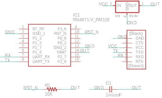
RN4871 wireless BLE

Failure
This BT RN4871 board as a footprint size error, so the SOLUTIOn is to machine it again.
Has you can see, I use same jumpers to connect to the FTDI because the board as the TX RX issue (they need to be exchanged) in order for the computer to comunicate properly with th RN4871 chip:
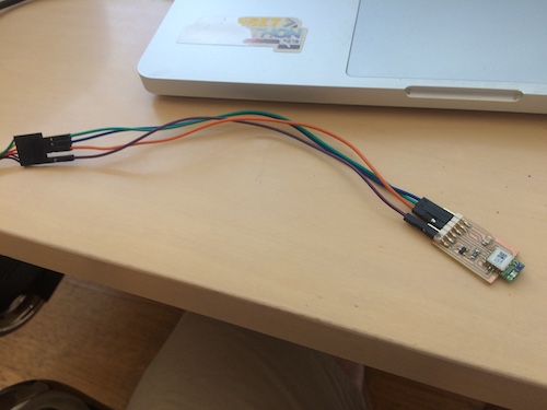
The board and the schema:
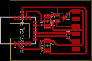
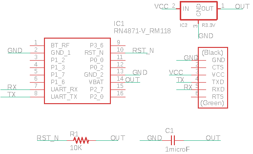
You can find all the files here.
As you can see I didn’t do it at the board but I leave here a warning:
Warning
Remember that BLE RN4871 RX goes to usb adaptor TX and RN4871 TX does to usb adapter RX.
After same more debuging… I start by folloing Joris Navarro Fab Academy site procedure (I’m using MAC): Open Terminal at your computer. Type to see the available serials: ls /dev/cu.* Copy the serial you are interested. Type to start comunication with the RN4871: miniterm.py /dev/cu.usbserial-FTFPE355 115200; The last number is the serial baudrate. The midle is the serial adress.
didn’t work!!!
Reading and reading the references listed downward. Debuging again… I think the possibility his the VCC is not well soldered.
I get here with miniterm.py
(base) MacBook-Pro-de-Antonio-2:~ antoniocarlosgoncalves$ miniterm.py /dev/tty.usbserial-FTFPE355 115200 — Miniterm on /dev/tty.usbserial-FTFPE355 115200,8,N,1 — — Quit: Ctrl+] | Menu: Ctrl+T | Help: Ctrl+T followed by Ctrl+H —
It didn’t work! It doesn’t accept comands $$$ to enter in command mode; even using the commands showned, they don’t work.
Hyphotesis: miniterm is not the right version for MAC; or the soldering of ny board is not correct;
(to be continued)
References
- Martyn Currey: http://www.martyncurrey.com/arduino-with-rn48701/
- Joris Navarro, FAB Academy 2018: http://fab.academany.org/2018/labs/barcelona/students/joris-navarro/classes/14--networking-and-communications/
- CoolTerm (for MAC): http://freeware.the-meiers.org/
- Bluetooth low energy Services, a beginner’s tutorial: https://devzone.nordicsemi.com/nordic/short-range-guides/b/bluetooth-low-energy/posts/ble-services-a-beginners-tutorial
- Basic BLE: https://chipkit.net/wiki/index.php?title=Basic_BLE#Hardware_Setup
- Arduino and BLE: https://github.com/SensorsIot/Bluetooth-BLE-on-Arduino-IDE
- microchip datasheet: http://ww1.microchip.com/downloads/en/DeviceDoc/RN4870-71-Bluetooth-Low-Energy-Module-User-Guide-DS50002466C.pdf
- Mike’s PBX Cookbook: https://pbxbook.com/other/mac-tty.html#screen
- miniterm.py: https://gist.github.com/bewest/4632563
- Neil lesson: http://academy.cba.mit.edu/classes/networking_communications/
- Last minute engineers: https://lastminuteengineers.com/
- ARDUINO I^2C_ Tutorial, from how to mechatronics
- Two arduinos communicating
- WIFI arduino’s
Simulate Radios and circuits
(to be continued)