5. Electronics production
February, 13
Assignments
group assignment: characterize the design rules for your PCB production process individual assignment: make an in-circuit programmer by milling the PCB, program it, then optionally try other PCB processes
Summary
For this ATtiny mission, the main goal is to programing and controlling inputs and outputs with hardware and software using this simple processors from the scratch.
We characterized and discuss the procedure steps, review them and implemented again. We took a long time reviewing and consolidate the procedure for the milling machine. I wanted to have those clear on my mind because its a machine I ever used. We also reviewed the security issues and the crucial steps to not mess arround with the propper machining. For the procedure milling machine steps, there is a need to follow this major ones (for details, see bellow):
| Software | What does it do? | Outcame |
|---|---|---|
| Eagle | drawing the PCB | export all the files by clicking on the icon Generate CAM data |
| FALTCAM | make the GCODE to controll the machine | export the gcode |
| CHILIPEPR | Prepare the machine: Dragg GCODE inside CHILIPEPR | Set zero references; Autoleveling; play gcode to cut vias, cutout board and drilling holes → HARD reset |
Downward there is my first programer PCB, just copied and milled with the help of Filipe. Next, I just want to see the path width possible for this machine. We use INKSCAPE with SVG file and put it on CHILIPEPR. Then follow the downward procedure (steps 2 to 21). Even for 0.2 mm its possible but the limit. So I will use 0.4 as a standard/reference.
I wanted to know this because of the PCB drivers for the boat project. We need 0.4, at least. Since we will also need current of 20 A, I test this trace width calculator
After same weeks working with the machine my utmost settings for this carve as a milling machine is the 0.3 mm V bit in a thickness copper of 0.035 mm :
| Parameter | Value |
|---|---|
| # passages | 3 |
| Pass overlap | 0,25 |
| Cut Z | -0.04 mm |
| Travel | 2.54 mm |
| feed rate | 100 |
| Tool dia | 0.3 mm |
| Combined Passes | select |
Cutout:
| Parameter | Value | Note |
|---|---|---|
| cut Z | -2 | thickness copper board |
| Travel z | 1 | height travel moving tool |
| Feed Rate | 100 | X, Y machine movement |
| Tooldia | 1.6 | |
| Spindle speed | 8000 | |
| Multi-depth | selected | several passages |
| Depth pass | 0.4 | each time 0.4 more |
For the TOOCHAIN that I ended up to use: Arduino IDE for the bootloader and for the boards programing. I will try in the future to use terminal, but I’m confortable for now with the former one.
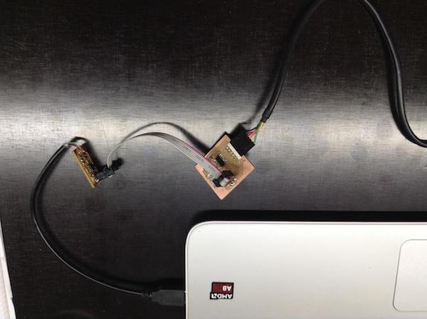
Revisiting this page, I found the need to have a picture about the programer connections that weren’t well documented.
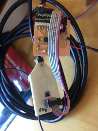
After week 17 - machine design, I find the need to have the pins documented, and ready acessible:
This week I took some time to learn a little bit of markdown and Processing. The later its needed because of the screen controling of the boat. The former it just to use colors to highlight same important details of the pages.
Using markdown, I found usefull the “Bold” and the “>” to highlight. I found out that the check boxes of the ask lists don’t work: “- []” and also, I would like to have same colors on the titles, but it doesn’t work also, for instance: “### Task list (to do’s) {: .gitlab-orange}”. I would like to have flowcharts. I tried mermaid but it doesn’t work as supposed, I think. I’m trying to find a way to put code inside a window where you can scroll it.
I also work a little bit on documenting the final project.
Todo
- Make traces with several diameters for several amounts of current intensity.
- Include photos on this document
- Procedural final Test
- Soldering
- Programing
- (completed in week 11) Documenting the ISP programing with FabISP for MAC
- Make the final path thickness test with EAGLE
- Flatcam gcode
Questions
- Insert higlights, comments using Markdown: done;
- Insert math formulas and symbols: answer: Latex symbols list.
- Discuss the ATtiny mission: programing and controlling inputs and outputs with hardware and software;
Work done
The circuit we are going to make its a programer using the ATtiny45, for processors that use AVR ISP. Its based on Brian work, which is based on the Fabtinystar. The USBtiny is a software implementation of the USB low-speed protocol for the Atmel ATtiny microcontrollers.
Milling machine procedure
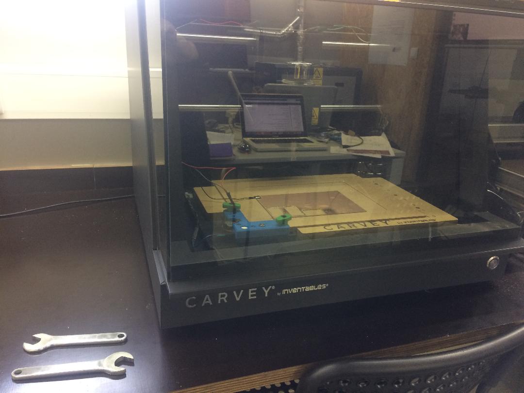
PCB fabrication - Machining The machine we are going to use its a Carvey, from Inventables. Its not suitable for the pcb job but the following procedure will do.
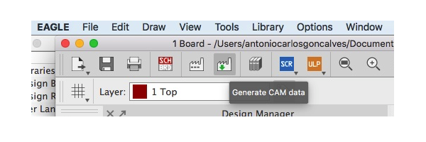
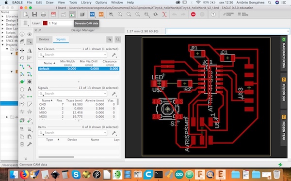
step 1: open EAGLE
After drawing your PCB, Press the Button “generate CAM data” (see this pic):
- IMPORTANT: design rules, in case of short distances between routes:
Menu: edit -> design rules -> clearance: everything 0.4 (this is the best for this machine we are using)
-
Use ALT + move button to move the route more precisely
-
Look at the several routes in order to see any Errors: Eagle show same red line shadowed
-
Select all, dragg all the board near the ORIGIN
Step 2: Open FlatCam
Open gerber file, “copper_top.gbr”.
Note
For the cutout choose the profile.gbr file
Step 3: select gbr file
Check if the cam dimensions are ok. If not, follow this note:
Note
click on “Options” and then select “Project Options”
(ATTENTION: NOT in the menu, just bellow)
check units mm
Then just bellow, “Gerber options”;
Plot options: select Plot and Solid
Isolation Routing: defines isolation path; I used several options to test the machine: - tool dia (diameter): 0.3 (0.2) 0.4 mm - width: 3 passages - Pass Overlap: 0.2 (0.1) 0.2 mm - Select “Combined Passes”
Click on selected, change the values like before and press “generate geometry”
Note
red lines means passages; green traces (copper); follow the gcode a see if there are spots where the tool doesn’t pass;
Click on project: select new file copper_top.gbr_iso
Next: click on selected
Create CNC job: parameters for the cut (Isolation cut): - CutZ: -0,05 mm (-0,04) 0.035 1 (cutting depth) (0,045) - Travel: 2.54 mm 1 - Feed rate (velocity): 100 mm/min (50) - Tooldia: 0,3 mm (0,2) (0.4) - Spindle: 12 000 (10 000)
Note
select multidepth only for cutout
Step 5: click on “Generate”
This step means: “generate the GCODE for the geometry of the PCB”
Blue lines means the machine path.
Go To Project and choose: copper_top.gbr_iso_cnc
Step 6: Export GCODE
go to selected and click on export G-CODE
Info
After this you don’t need FlatCam anymore: only for the cutout, step 22.
Step 7: open folder serial-port-json-serverӦ
allows computer to comunicate with the Carvey machine
in the computer connected to the machine, the folder “serial-port-json-server” and RUN serial-port-json-server
Step 8: Turn machine ON (see front blue light)
Note: we don’t use auto levell: less precision
Step 9: Open chilipepr online
Follow this link. Open Grbl workspace.
Step 10: Select USB serial port
select in the Lower right corner (you need to scroll) push CRTL+X (upper) and click on ALARM (Pink) See state: Idle/Mpos
Step 11: bed checking and Tool mounting (Isolation tool)
low strenght when screwing the tool connect the “sensor connector” and check if led lights (just touch the base) connect the machine tool to the sensor (if the lights off, reconnect to base) JOG Position (upper right): select X, Y, Z until LED red lights up: trial and error
Danger
Check if the bed is not loose because, in the end, the isolation could not be correct.
Step 12: HARD reset
DO IT VERY CAREFULLY!
- Clic on Zero out on chilipepr: it will define the reference (0,0,0).
IMPORTANT: see if the machine connector is plugged onto the led levelling system
In the final Z jog go 0.01 mm each time, and when it lights go up 0.01 and again 0.01 when the led lights.
be carefull, only on zero out!!!!
- Turn off machine
- Disconnect USB
- Reconnect USB
- Turn ON machine
- reselect USB serial Port on chilipepr (its a repetition of step 10)
- CRTL X and click on ALARM: check if “Idle/Mpos” message content
- Zero Out, again
Z Up (50 mm) Be prepared!!! Click on “GO to Zero” (if the machine isn’t doing what is suppose: QUIKCLY push the very special button (iman): a really “very special” SECURITY BUTTON, the tape!
NOTE: everytime the machine is stopped, there is a need to reset to a new (0,0) (see step 11)
Step 13: Dragg GCODE file to the CHILIPEPR window online software
It will show the previewed GCODE; Do it in this sequence: drag the GCODE and them send the “Send Auto-levelled Gcode to workspace” after the autolevelling done (see the next steps)
Info
If your board is not in the reference (0,0), go back to the FLATCAM software and change it in the offset at the selected menu.
Step 14: click on the AUTOLEVEL tool on the top left
Step 16: Click on RUN and then on play button
ignore pre-run settings for now mapping the surface
click on “Let get probing” to do the automatic levelling
Step 17: click on Post Run (on the left)
Step 18: click on “Send Auto-levelled Gcode to workspace”
automatically changed the GCODE new window: check milimeters Click on auto-levell to see down bellow the “GCODE” window; confirm that you have on GCODE the line saying (al z mod 1) (Its hidden under the small arrow)
Step 19: remove cable attached to the tool
Step 20: close the door
Step: 21: press on autolevell and then on play GCODE
After finnished, clean the PCB
Info
Don’t move the X,Y axis!!! You will loose this reference.
Step 22: cut out: change tool
Z up change tool
Step 23: Attach cable
- down Z until LED lights
STEP 24: HARD RESET (see above, step 12)
Info
since we are not doing autolevell, REMOVE cable after HARD RESET
Step 25: open Flat Cam
Step 26: import gerber file (profile.gbr)
Step 27: Board cutout
Select board cutout on the project option under the menu Options
Choose mm on project options
Choose selected, scroll to board cutout.
Scroll to board cutout
parameters: Tool dia: 1.6 Margin: 0 (distance between cut and line) Gap size: 0 (remove gaps)
Step 28: push generate geometry
Go to menu project and select this file: profile.gbr_cutout
Step 29: selected
Create cnc job: cut Z: -2 (thikness copper board) Travel z: 1 :(height travel moving tool) Feed Rate: 100 Tooldia : 1.6 Spindle speed 12000 (10000) Multi-depth: selected (several passages) Depth pass: 0,4 (each time 0.4 more)
Step 30: push generate.
new file: profile.gbr_cutout_cnc
Step 31: export GCODE
go to selected and push export G-Code (give it a name), and save
Step 32: drag that file to chilipepr
Step 33: close the door
- Remove cabble
- Click on PLAY on GCODE to cutout
IMPORTANT: after the cutting see if the machine connector is plugged onto the led levelling system and unplug it
Security
- close the door when Working
- HARD RESET double check carefully done (check HARD RESET sept 12)
- Remove the cable used to (,0) reference setting
- Malfunction: press BLUE button
- Don’t leave the machine unattended.
Path test
We did the drawing with INKSCAPE, save it on SVG and imported it to FLATCAM, following steps 2 to 21. The result is pretty good:
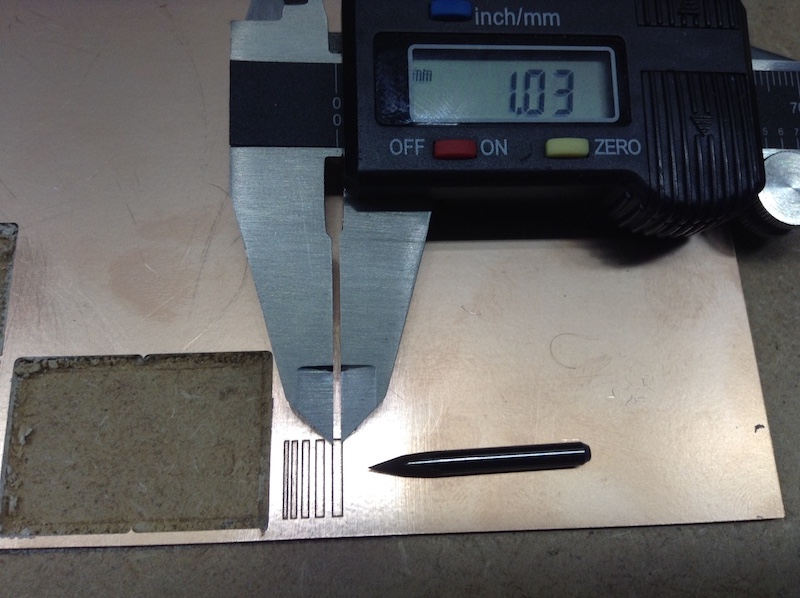
It was ok, but I want the copper to be removed within the paths. So, next time, we will do it using EAGLE instead of INKSCAPE.
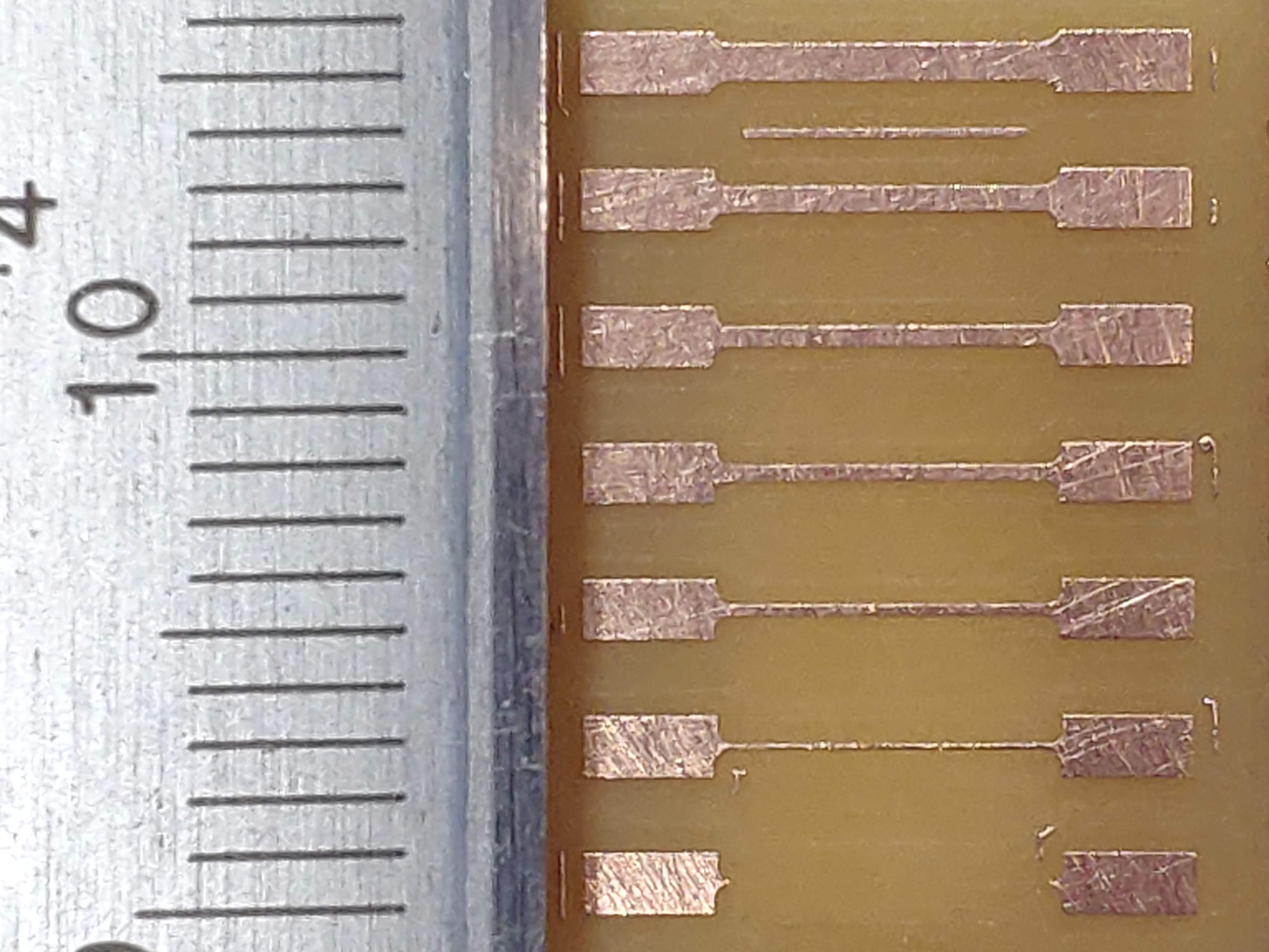
Filipe did it with Eagle and shared with us the results, showed that 0.2 mm is the limit for this machine we are using:
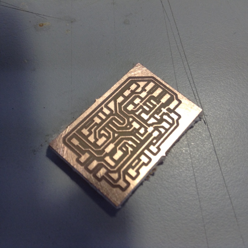
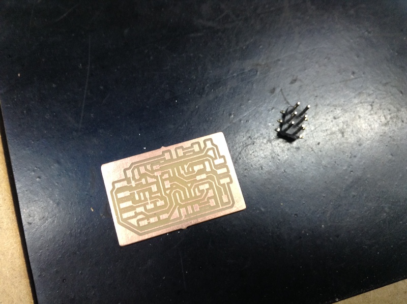
PCB programmer
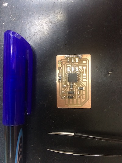
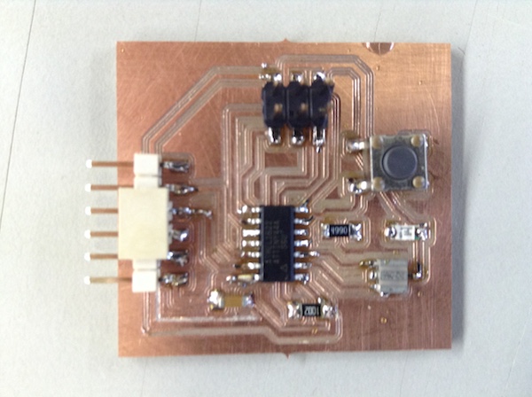
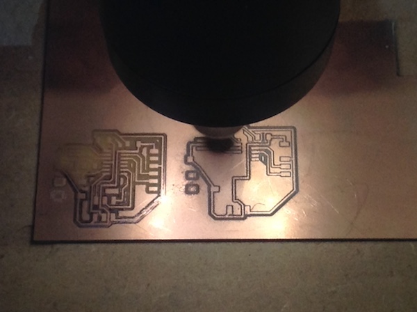
My first programer. The machining result:
Materials needed
| Qty | Description | Notes |
|---|---|---|
| 1 | C1 | 100 nF |
| 2 | D1 , D2 | Zener diode 3.3V, blue bar directed to the GRD |
| 2 | D3 , D4 | Zener diode 3.3V, blue bar directed to the GRD |
| 1 | R3 , R4 | 49 \omega |
| 1 | R1 , R6 | 1 K \Omega |
| 2 | R2 , R5 | 499 \Omega |
| 1 | ATtiny 45 |
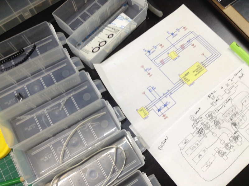
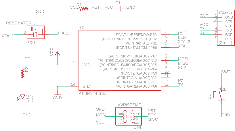
Schematics
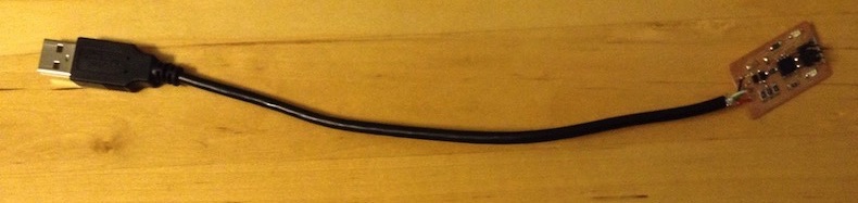
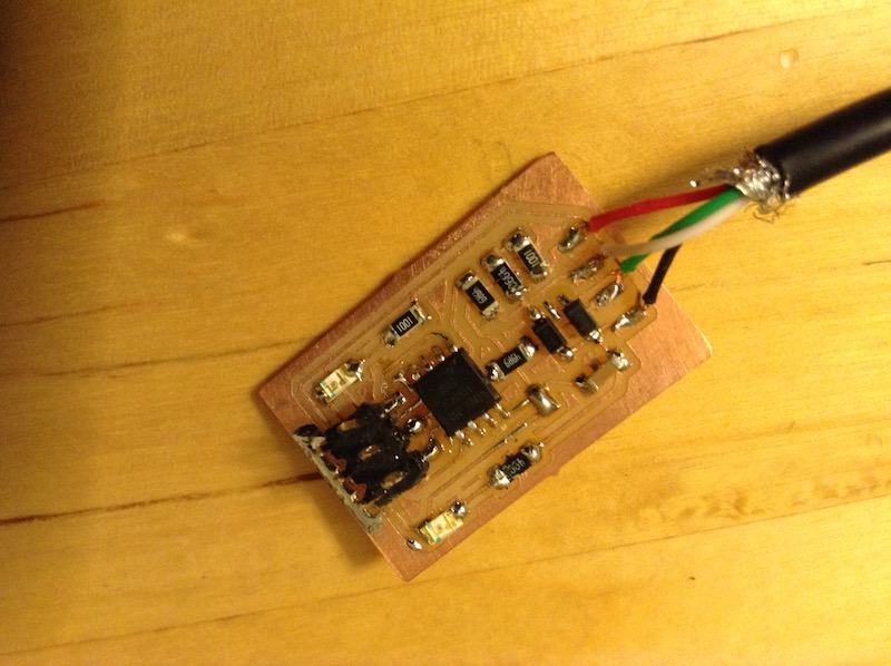
My board is based on this one, but I use wires and a USB cable to be easier to make the PCB:
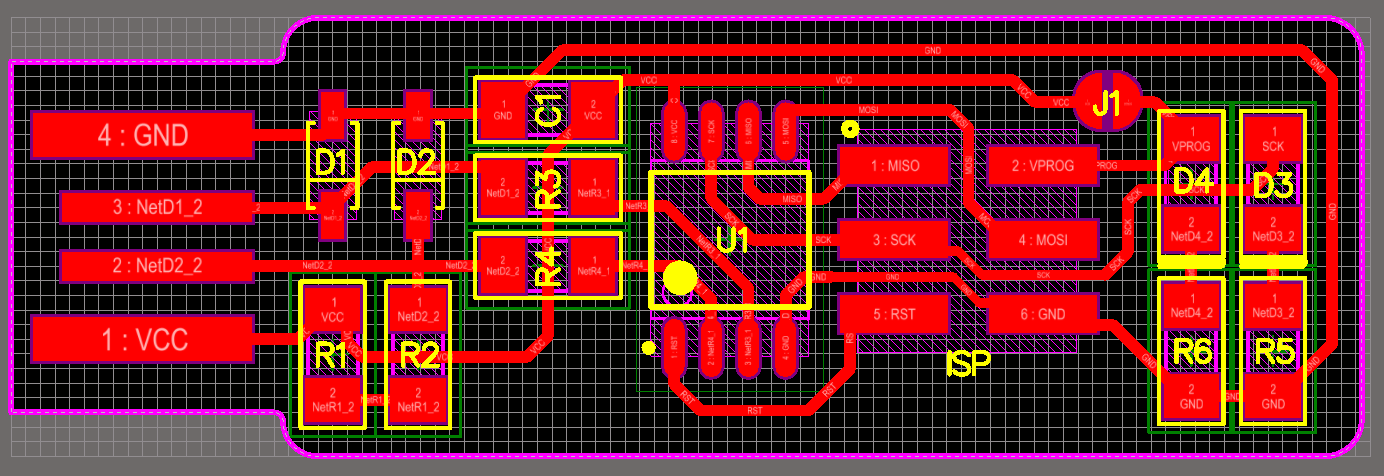
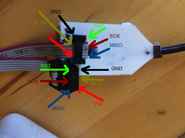
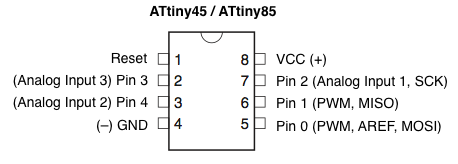
The pins are very important to keep in mind, so this image show the important pins used for programing the boards, namely, GND, Vcc, SCK, MISO, MOSI and RST:
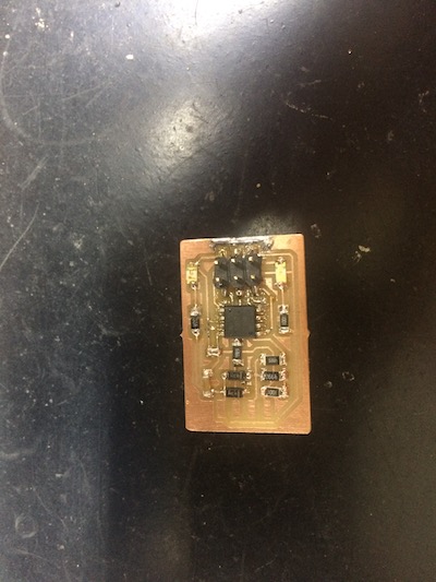
Next stop: Soldering!
With this in mind:
I started and its really small:
In the middle:
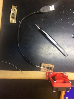
Soldering the USB wires. The code colors:
- Black - ground
- Green - data +
- White - data -
- Red - V_{cc}
Result:
Check the board: debugging
- Compare the circuit schetch and the components: is it all correct against the schematics? The components are positions, orientations, type of components in the correct places?
- Components flat on the board?

- Solder connections must look metalic in color and smooth between the pin and the path. If not reflow the solder.
- Is there unwanted solder between nearby paths (traces) and pins?
- Use a multimeter to check for shorts between VCC and GND, and conections between the circuit paths.
- Check the 5V between GND and Vcc.
- Test on a tested board programing: in thsi case I use Linux that Filipe as already prepared, and it worked just fine.
Next Stop: programming!
Since I use MAC and the ISP programer is working, it iss necessary to download CROSSPACK.
green led -> ative communication Red led -> indicate if the target as is own power
in-system programmer (ISP), a piece of hardware used to load programs
Firmware
Download the source code here
Open your terminal program and change the directory till your source code directory; in my case, I follow this lines, and make a directory.
Mac getting Started: see cross pack avr manual (file with the instalation) bash$ cd ~/Documents bash$ mkdir AVR bash$ cd AVR bash$ avr-project Demo bash$ open Demo
On the opened window, Choose the file “Demo.xcodeproj” and click twice.
When the Xcode window open you can see two files inside the firmware folder: - Makefile controls the build process; - main.c contains the C source code for the project;
On the Xcode you just opened, type:
DEVICE = attiny45 CLOCK = 8000000 PROGRAMMER = atmelice_isp OBJECTS = main.o FUSES = -U hfuse:w:0xd9:m -U lfuse:w:0x24:m
I used this programmer tool: Atmel-ICE that’s why the PROGRAMMET is atmelice_isp.
The name of the device is just like that: attiny45.
How to connect with the Atmel-ICE?
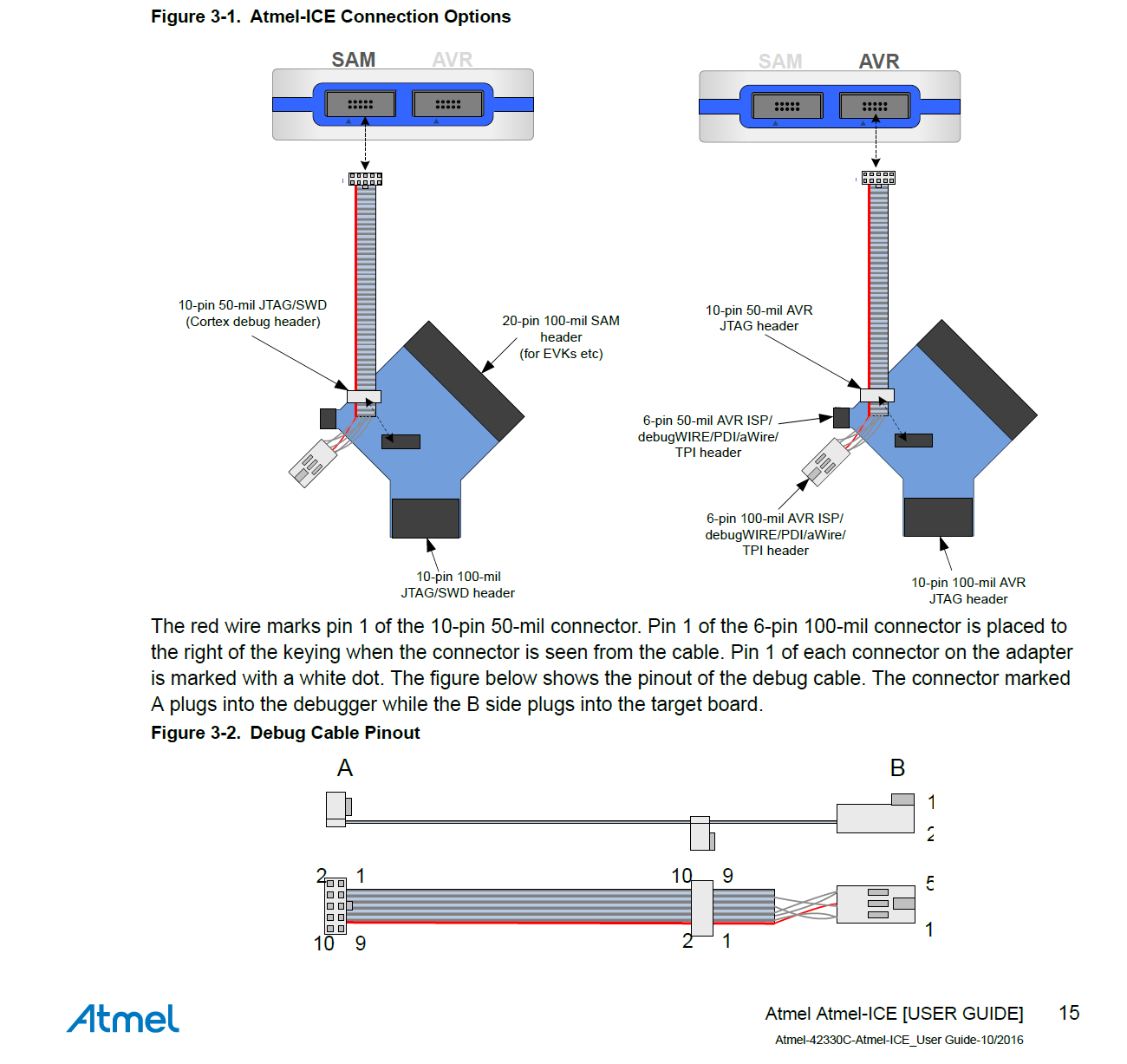
Source: https://forum.arduino.cc/index.php?topic=442133.0
On the board I want to program, pin 1 has the MISO signal connected to it (check the schematics) and your board.
Open Terminal again
Choose the directory firmware.
Documents antoniocarlosgoncalves$ cd AVR AVR antoniocarlosgoncalves$ cd Demo Demo antoniocarlosgoncalves$ ls Demo.xcodeproj firmware Demo antoniocarlosgoncalves$ cd firmware
Averdude
AVRDUDE = avrdude -c atmelice_isp -P usb -p $(DEVICE) # edit this line for your programmer
Run make and, if everything ok, you should get this message:
firmware antoniocarlosgoncalves$ make avr-gcc -Wall -Os -DF_CPU=8000000 -mmcu=attiny45 -o main.elf main.o rm -f main.hex avr-objcopy -j .text -j .data -O ihex main.elf main.hex avr-size –format=avr –mcu=attiny45 main.elf AVR Memory Usage
Device: attiny45
Program: 54 bytes (1.3% Full) (.text + .data + .bootloader)
Data: 0 bytes (0.0% Full) (.data + .bss + .noinit)
This will erase the target chip flash memory, and program it with the main.hex file you built.
What do you need? - 1. Install ATtiny support on the ARDUINO IDE - 2. Programing the ATtiny45 to write the program on the target processor - 3. Configuring the ATtiny to run at 8 MHz - 4. A processor to be programed with ISP feature.
PROBLEM: avrdude version.
SOLUTION: install last version using this procedure listed here: it will install BREW. After this just type at the terminal: brew install avrdude.
Detailed steps and messages
Last login: Fri Mar 15 10:59:10 on console
MBPdeAntonio2:~ antoniocarlosgoncalves$ ruby -e "$(curl -fsSL https://raw.githubusercontent.com/Homebrew/install/master/install)" < /dev/null 2> /dev/null
==> This script will install:
/usr/local/bin/brew
/usr/local/share/doc/homebrew
/usr/local/share/man/man1/brew.1
/usr/local/share/zsh/site-functions/_brew
/usr/local/etc/bash_completion.d/brew
/usr/local/Homebrew
==> The following new directories will be created:
/usr/local/Homebrew
==> /usr/bin/sudo /bin/mkdir -p /usr/local/Homebrew
Password:
==> /usr/bin/sudo /bin/chmod g+rwx /usr/local/Homebrew
==> /usr/bin/sudo /bin/chmod 755 /usr/local/share/zsh /usr/local/share/zsh/site-functions
==> /usr/bin/sudo /usr/sbin/chown antoniocarlosgoncalves /usr/local/Homebrew
==> /usr/bin/sudo /usr/bin/chgrp admin /usr/local/Homebrew
==> Downloading and installing Homebrew...
HEAD is now at db42dd0 Merge pull request #5881 from EricFromCanada/alias-installed-satisfied
==> Homebrew is run entirely by unpaid volunteers. Please consider donating:
  https://github.com/Homebrew/brew#donations
==> Tapping homebrew/core
Tapped 2 commands and 4738 formulae (4,995 files, 12.4MB).
Already up-to-date.
==> Installation successful!

==> Homebrew has enabled anonymous aggregate formulae and cask analytics.
Read the analytics documentation (and how to opt-out) here:
  https://docs.brew.sh/Analytics

==> Homebrew is run entirely by unpaid volunteers. Please consider donating:
  https://github.com/Homebrew/brew#donations
==> Next steps:
- Run `brew help` to get started
- Further documentation:
    https://docs.brew.sh
MBPdeAntonio2:~ antoniocarlosgoncalves$ brew install avrdude
==> Installing dependencies for avrdude: libelf, libusb, libusb-compat, libftdi0 and libhid
==> Installing avrdude dependency: libelf
==> Downloading https://homebrew.bintray.com/bottles/libelf-0.8.13_1.high_sierra
######################################################################## 100.0%
==> Pouring libelf-0.8.13_1.high_sierra.bottle.tar.gz
🍺  /usr/local/Cellar/libelf/0.8.13_1: 12 files, 222.3KB
==> Installing avrdude dependency: libusb
==> Downloading https://homebrew.bintray.com/bottles/libusb-1.0.22.high_sierra.b
######################################################################## 100.0%
==> Pouring libusb-1.0.22.high_sierra.bottle.tar.gz
Error: The `brew link` step did not complete successfully
The formula built, but is not symlinked into /usr/local
Could not symlink include/libusb-1.0
Target /usr/local/include/libusb-1.0
already exists. You may want to remove it:
  rm '/usr/local/include/libusb-1.0'

To force the link and overwrite all conflicting files:
  brew link --overwrite libusb

To list all files that would be deleted:
  brew link --overwrite --dry-run libusb

Possible conflicting files are:
/usr/local/include/libusb-1.0
/usr/local/lib/libusb-1.0.a
/usr/local/lib/libusb-1.0.dylib
==> Summary
🍺  /usr/local/Cellar/libusb/1.0.22: 29 files, 514.8KB
==> Installing avrdude dependency: libusb-compat
==> Downloading https://homebrew.bintray.com/bottles/libusb-compat-0.1.5_1.high_
######################################################################## 100.0%
==> Pouring libusb-compat-0.1.5_1.high_sierra.bottle.tar.gz
🍺  /usr/local/Cellar/libusb-compat/0.1.5_1: 14 files, 94.3KB
==> Installing avrdude dependency: libftdi0
==> Downloading https://homebrew.bintray.com/bottles/libftdi0-0.20.high_sierra.b
######################################################################## 100.0%
==> Pouring libftdi0-0.20.high_sierra.bottle.2.tar.gz
🍺  /usr/local/Cellar/libftdi0/0.20: 20 files, 190.6KB
==> Installing avrdude dependency: libhid
==> Downloading https://homebrew.bintray.com/bottles/libhid-0.2.16.high_sierra.b
######################################################################## 100.0%
==> Pouring libhid-0.2.16.high_sierra.bottle.1.tar.gz
🍺  /usr/local/Cellar/libhid/0.2.16: 18 files, 180.5KB
==> Installing avrdude
==> Downloading https://homebrew.bintray.com/bottles/avrdude-6.3_1.high_sierra.b
######################################################################## 100.0%
==> Pouring avrdude-6.3_1.high_sierra.bottle.tar.gz
🍺  /usr/local/Cellar/avrdude/6.3_1: 14 files, 1.9MB
==> `brew cleanup` has not been run in 30 days, running now.
ABOUT BREW, explained here.
First board to be programed.
At the same time I did another board with the ATtiny44 to be programed.
CAM data
Eagle sch file
Eagle brd file:
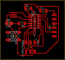
On Eagle I generate grb files to be used at FLATCAM to generate the GCODE for the chillipepr to control the xcarve machine. In FLATCAM I did to things:
Before making the boards I get EASEL onliine to make the bed for the copper. I use a 6 mm flat bit tool to prepare the bed and carefull glue it with a thin film.
programing
Success!
Milling
Improving…
Parameters:
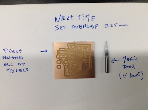
Note
I think that the 0.25 is to much but it shows better results.
Gcode
All the files here.
One of it:
G21 G90 G94 F75.00 G00 Z1.0000 M03 S10000 G4 P1 G00 X18.2400Y-0.9270 G01 Z-0.2000 G01 X-0.9270Y-0.9270 G01 X-0.9270Y36.1570 G01 X18.2400Y36.1570 G00 X18.2400Y36.1570 G01 Z-0.4000 G01 X-0.9270Y36.1570 G01 X-0.9270Y-0.9270 G01 X18.2400Y-0.9270 G00 X18.2400Y-0.9270 G01 Z-0.6000 G01 X-0.9270Y-0.9270 G01 X-0.9270Y36.1570 G01 X18.2400Y36.1570 G00 X18.2400Y36.1570 G01 Z-0.8000 G01 X-0.9270Y36.1570 G01 X-0.9270Y-0.9270 G01 X18.2400Y-0.9270 G00 X18.2400Y-0.9270 G01 Z-1.0000 G01 X-0.9270Y-0.9270 G01 X-0.9270Y36.1570 G01 X18.2400Y36.1570 G00 X18.2400Y36.1570 G01 Z-1.2000 G01 X-0.9270Y36.1570 G01 X-0.9270Y-0.9270 G01 X18.2400Y-0.9270 G00 X18.2400Y-0.9270 G01 Z-1.4000 G01 X-0.9270Y-0.9270 G01 X-0.9270Y36.1570 G01 X18.2400Y36.1570 G00 X18.2400Y36.1570 G01 Z-1.6000 G01 X-0.9270Y36.1570 G01 X-0.9270Y-0.9270 G01 X18.2400Y-0.9270 G00 X18.2400Y-0.9270 G01 Z-1.8000 G01 X-0.9270Y-0.9270 G01 X-0.9270Y36.1570 G01 X18.2400Y36.1570 G00 X18.2400Y36.1570 G01 Z-2.0000 G01 X-0.9270Y36.1570 G01 X-0.9270Y-0.9270 G01 X18.2400Y-0.9270 G00 Z1.0000 G00 X19.8400Y-0.9270 G01 Z-0.2000 G01 X39.0070Y-0.9270 G01 X39.0070Y36.1570 G01 X19.8400Y36.1570 G00 X19.8400Y36.1570 G01 Z-0.4000 G01 X39.0070Y36.1570 G01 X39.0070Y-0.9270 G01 X19.8400Y-0.9270 G00 X19.8400Y-0.9270 G01 Z-0.6000 G01 X39.0070Y-0.9270 G01 X39.0070Y36.1570 G01 X19.8400Y36.1570 G00 X19.8400Y36.1570 G01 Z-0.8000 G01 X39.0070Y36.1570 G01 X39.0070Y-0.9270 G01 X19.8400Y-0.9270 G00 X19.8400Y-0.9270 G01 Z-1.0000 G01 X39.0070Y-0.9270 G01 X39.0070Y36.1570 G01 X19.8400Y36.1570 G00 X19.8400Y36.1570 G01 Z-1.2000 G01 X39.0070Y36.1570 G01 X39.0070Y-0.9270 G01 X19.8400Y-0.9270 G00 X19.8400Y-0.9270 G01 Z-1.4000 G01 X39.0070Y-0.9270 G01 X39.0070Y36.1570 G01 X19.8400Y36.1570 G00 X19.8400Y36.1570 G01 Z-1.6000 G01 X39.0070Y36.1570 G01 X39.0070Y-0.9270 G01 X19.8400Y-0.9270 G00 X19.8400Y-0.9270 G01 Z-1.8000 G01 X39.0070Y-0.9270 G01 X39.0070Y36.1570 G01 X19.8400Y36.1570 G00 X19.8400Y36.1570 G01 Z-2.0000 G01 X39.0070Y36.1570 G01 X39.0070Y-0.9270 G01 X19.8400Y-0.9270 G00 Z1.0000 G00 Z1.0000 G00 X0Y0 M05
programing
links - LATEX - markdown - markdown formulas