Final Project
July, 3rd
Guidelines
This are the project guidelines proposed by the FAB ACADEMY Team: What will it do? Who’s done what beforehand? What will you design? What materials and components will be used? Where will come from? How much will they cost? What parts and systems will be made? What processes will be used? What questions need to be answered? How will it be evaluated? Your project should incorporate 2D and 3D design, additive and subtractive fabrication processes, electronics design and production, microcontroller interfacing and programming, system integration and packaging Where possible, you should make rather than buy the parts of your project; Projects can be separate or joint, but need to show individual mastery of the skills, and be independently operable
Summary
This catamaran called aqua, presented to FAB ACADEMY comunity last june, 19th (video here), will be used for research and investigation for high schools sudents, profession and polytechnic schools at the University level. There are several similar projects, at the educational and academic level as well as at the professional industry world. Same of them are documented at the first assignment here. I design all the structure in 3D, the electronics boards and the programing. The materials used for the structure were the ususal PLA polymer used at 3D printing, ESP walls heat isolation and cork, milled with a CNC and 3D printed. Of course, electronics components, like leds, resistors, capacitors, BLE chip, ATmega328, thermistors, phototransistors, servos, drivers, wires and DC motors. They were bought at local and online stores and it costs arround 1200 euros. I made the hull, the electronics boards, the wiring, soldering and the programing. The main processes will be directly related to Digital Fabrication, namely, 3D design and printing, electronics design and production, CNC miling and cutting, as well as molding and casting. The main question is to know if it is possible to build a small catamaran, as ecological as possible and strong enought, to be used for research and educational purposes. Evaluation of this project will be done comparing the starting idea with the pausing point at the end of this course, that is, today! The project incorporate 2D and 3D design, additive and subtractive fabrication processes, electronics design and production, microcontroller interfacing and programming, system integration and packaging. This project were built by my own responsability with several contributors.
list of files: Central body slices, EASEL files portboard hull here at my own account) and the Starboard hull here
All the zipped files, SCH, BRD and GCODE, can be found here and here; or at my personal google drive.
Idea
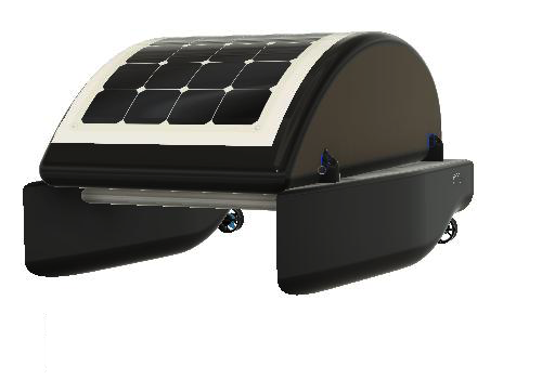
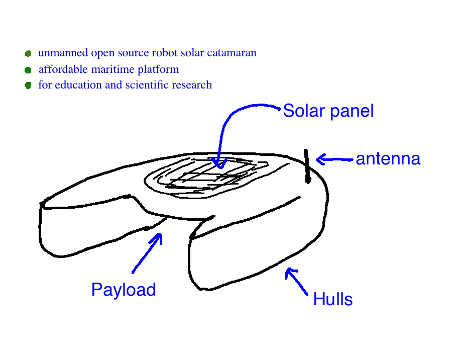
The main purpose of this opensource unmanned robot solar catamaran boat is to be used as an affordable maritime platform for education and scientific research. This platform prototype is designed to be 80% ecofriendly, built using Digital Fabrication tools, processes and cooperative opensource projects already in place and developed.
Copyright
Aqua final Fab Academy 2019 project, includes fabrication procedures and operation, hardware and software applied for the board at the boat to control the boat, the inflatable system (water presence inside the hulls), the safety lights and measure light intensity, UVA and air and water temperature.
António Gonçalves 3/7/2019
© Lab Aberto Fab Lab 2019 This work may be reproduced, modified, distributed, performed, and displayed for any purpose. Copyright is retained and must be preserved. The work is provided as is; no warranty is provided, and users accept all liability.
Features
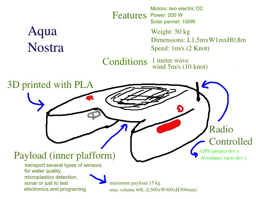
It uses 3D printed with PLA (materials more environment friendly) and the inner hull structures are made with MDF/Cardboard laser cutted. The molds and casts resins we are planned to use are also environmental friendly. It will have control board for temperature sensor, UV index output and safety control.
It can be controlled by GPS way points or radio using Opensource projects available online, like ROS and ARDUPILOT. Does have telemetry and video.
The design enables to transport an inner platform where it is possible to assembly several types of sensors for water quality, microplastics detection, sonar or just to test electronics, avoidance systems and programing.
This is a prototype of a catamaran of 1,5 m long, a width of 1 m and 0,8 m heigh. It weights around 50 kg, it has a maximum payload of 15 kg with a max volume 60L (L500xW400xH300mm) and can move at speed of 1 m/s.
It has two security buttons to stop running and two inflatable bags in the case of sink.
The main source of energy is solar but it can be charged when docked. It as two DC motors of 100 W each.
This project can be promoted as an assembled vessel or DIY kit.
compare the idea with the outcame
Looking at the initial idea the final outcame is far from it but I manage to do a major step in order to start a crucial project at our Fab Lab, not yet a Fab Lab, but in the making, lab aberto. Its mostly a breakthrough into the tecnology, electronics, programing and digital fabrication. This does not mean that all the goals were completed, far from it. In my view I did only ¼ of all the catamaran goals, and the 80% eco boat was just completed half way.
The initial idea:

The result for the starboard hull:

Positive and negative
| Positive | Negative |
|---|---|
| Knowledge about programing, electronics and digital fabrication | Final project to much ambitious |
| Experiencing and testing new processes | Time managment |
| Need to do: improve the browser code, include Bluetooth, Calibrate the sensors and Test it on water |
Future
For the future, this catamaran shoul be tested in a context of researh and education and should be controlled by radio and GPS (using Opensource projects available online, like ROS and ARDUPILOT), Integrate video, include the transport of a inner platform, test the possibility of use cardboard to make the hulls, include security buttons to stop the operation and assembly a solar pannel. Hope that in ficve years this project will achieve a very robust phase.
Details
Starboard Hull
The hull was made in three parts, two of them 3D printed, and the central was previously sliced and cutted at CNC machine.
First modeling:
Cad
The preliminary CAD design is here
And the STL of the preliminary versions 2 and version 4
The 7th version can be found here
Boat design reference: https://fenix.tecnico.ulisboa.pt/downloadFile/395142227927/Julien_Melot_MSc_Thesis_v.2.pdf
Newest profile:

One of the parts at the CURA software:

Glued together all the 3D printed parts before glue them to the central CNC milled part:

Warning
Becarefull to glue the parts correctly because in my case on of the parts should be more up then the others, so the cover dooesn’t fit well as you can see on the videos and in this pic:

Cutting
The 3D design of hull the central body was slided using the Autodesk SLICER (part of the FUSION360).

Filipe Help clean the slicer fusion dxf plans with AUTOCAD in order to be used in the online EASEL (files here at my own account).
The slicer plan files:


Were milled at this X-Carve:

Warning
Be carefull with the thickness of the parts when you are analysing the files to cut: increase it or you will have a hull with dangerous thickness.

After all the 2D parts were glued you have to sanding to adjust the parts to the hull original curves before you resin it:

The 3D parts were separated in smaller STL files in order to be possible to print them at our own 3D printers.
For the PortBoard Hull in the 7th version, the slice files are here.

I will test the use, instead of EPS, as in the starboard hull, I will use cork.
Warning
Since I use a cover for the bow, the slicer includes that lines that are not needed. I use this time QCAD to remove that extra lines. There is always a need to **clean*+ the file.
The clean files can be found here.
Warning
To use this files with easel from Fusion 360 slicer Filipe help with the Autodesk command overkill and join in order to kill all the sobrepositions and join the points in the same line in only one line.
Testing feed rate, spindle speed for cork:


Result: I found that cork is very friendly to feedrates of 1000 mm/min and a spindle speed of 3 or 4 in the scale of the XCARVE spindle.

Cutting files here:

Glue testing:

They seem to glue the cork very well but the one that is more robust in contact with water is the UHU glue at the right on the photo.
I’ve try it also with resin as a glue component and it seems to work fine, very resistent:

Painting:

Portboard hull rising parts:


Next stop: glue it! Glue it with a normal glue:


And press it!

Testing the cork glued just with epoxi resin, the results are very good. Need to test in the water.

Since the waals are to thin and the cork is not homogeneous dense this problems might happen: broken parts:

The solution was to cut this parts and mill a wall and glue it all together.
Assembly the catamaran
(to be continued)
Electronics
The main board include the ATmega328p processor, the BLE RN4871, terminals with 8 V, 5 V and 3.3 V, for the servo, the processor and the BLE. It comunicates thougth serial by I2C and FTDI, Future Technology Devices International. It as four extra terminals, 6 terminals for the air and water temperature, 2 terminals for the water sensor, and 6 pins for UVA (VEML6070 sensor) and visible light sensor (phototransistor): SCL, SDK, ACK, power and light sensor pinout


Info
Debuging and soldering:

This video is helpfull: Soldering: https://www.youtube.com/watch?v=QzoPxvIM2qE
If you need this: PCB trace calculations
Ending this board was a major major achievement!
All the files can be found here
More details at this assignment.
Warning
At the debuging I found to errors: one related with the powering the LED lights for the security, and the other related with RX TX of the BLE: they need to be exchanged.
The final board with the problems solved can be found here and the files pictures are this one’s:


Programing
The Arduino programing measures the data related to the sensors refered above, controll the board with letter’s:
- if a, command to measure data
- if b, command to stop reading data
- if c, activate servo,
- if d, turn leds on,
- if e. turn leds off;
It reacts in the presence of water inside the hull and lights up the security lights when its dark.
In the future it will have a phone and a better web interface using the BLE RN4871.
The browser doesn’t communicate directly with the serial so there is a need to create websockets and callback functions, that react to serialport events:
list – the program asks for a list of ports.
connected – when the sketch connects to a webSocket-to-serial server
open – a serial port is opened
close – a serial port is closed
data – new data arrives in a serial port
error – something goes wrong.
On this part I will use libraries and arduino IDE scripting that has a major problem, it could be so heavy that the atmega328 can have enought memory.
The sensors that I be using for the boat operation are listed at this next table.
| sensors | Outcame | Operation | note |
|---------|-----------|------|-----|
| UVA | UVA readings at the console | It should operate when the user push a button at the console | UV index: https://en.wikipedia.org/wiki/Ultraviolet_index |
| Water Temperature | Water temperature at the console | It should operate when the user push a button at the console | |
| Air Temperature | Water temperature at the console | It should operate when the user push a button at the console | |
| Light sensor | Boat safety lights on, aknowledge at the console | Always in operation, readings each 5 minutes; the user should turn them on from the console | |
| Water sensor | Push the valve that ignites the inflatable bag, readings each minute | Should work when the hulls are flooded or when the user push the safety button | This sensor is positioned at half the hight of the hull |
Arduino
Arduino library installation: https://learn.adafruit.com/adafruit-all-about-arduino-libraries-install-use
Fuses calc: http://www.engbedded.com/fusecalc/
ATMEGA pins: ![] (https://camo.githubusercontent.com/ebdfb269328ed8c2b26f2fc37d46a9fc68634584/68747470733a2f2f692e696d6775722e636f6d2f5a51736a4c774c2e6a7067)
mini core: https://github.com/MCUdude/MiniCore
pin interrupt (basic): https://www.arduino.cc/reference/en/language/functions/external-interrupts/attachinterrupt/
pin interrupt lecture (advanced): https://courses.cs.washington.edu/courses/csep567/10wi/lectures/Lecture7.pdf
Interupt explained: https://www.arxterra.com/11-atmega328p-external-interrupts/?v=e71bc9c013d9
pin change example (advanced): https://playground.arduino.cc/Main/PinChangeInterrupt/
Enable internal pull up to the pins not used: p.62, datasheet
Interrupts http://www.gammon.com.au/interrupts https://www.teachmemicro.com/arduino-interrupt-tutorial/
https://editor.p5js.org/fqantonio/sketches/z4y7rtOwm
References: https://p5js.org/examples/dom-input-and-button.html
https://editor.p5js.org/dano/sketches/SJq0FKc97
String on Arduino explained: https://hackingmajenkoblog.wordpress.com/2016/02/04/the-evils-of-arduino-strings/
Serial reading on Arduino explained: https://hackingmajenkoblog.wordpress.com/2016/02/01/reading-serial-on-the-arduino/
Terminal
mk dir aquaSerial
cd aquaSerial
touch index.js
Websocket
You should have this serialport library installed, so type this: npm install ws; Tutorial: https://itp.nyu.edu/physcomp/labs/labs-serial-communication/lab-serial-input-to-the-p5-js-ide/: p5 Serial Control https://itp.nyu.edu/physcomp/labs/labs-serial-communication/lab-serial-communication-with-node-js/
Serial: https://itp.nyu.edu/physcomp/labs/labs-serial-communication/lab-serial-input-to-the-p5-js-ide/
This video shows what it does at this moment:
Arduino Programing ``` // // Aqua final Fab Academy 2019 project, software for the board at the boat //to control the inflatable system (water prensence inside the hulls) the safety // lights and measure light intensity, UVA and air and water temperature. // References: https://learn.adafruit.com/adafruit-veml6070-uv-light-sensor-breakout/ //https://www.arduino.cc/reference/en/language/functions/external-interrupts/attachinterrupt/ // Based on this work: https://github.com/chipKIT32-libraries/RN487x/blob/master/examples/BLE_SensorApp/BLE_SensorApp.ino // // António Gonçalves // 19/6/2019 // // © Lab Aberto Fab Lab 2019 // This work may be reproduced, modified, distributed, // performed, and displayed for any purpose. Copyright is // retained and must be preserved. The work is provided // as is; no warranty is provided, and users accept all // liability.
#include <Arduino.h>

//math
#include <math.h>

//RN4871
//#include <RN487x_BLE.h>

//U2C communication with UVA sensor, VEML6070
#include <Wire.h>
#include "Adafruit_VEML6070.h"

Adafruit_VEML6070 uv = Adafruit_VEML6070();

// state
char state = "b";//default state variable, BT not listening for the comands from the console, state has its own protocol
  //if a, command to measure data
  //if b, command to stop reading data
  //if c, activate servo,
  //if d, turn leds on,
  //if e. turn leds off;

//Sensors

//temperature
int airPinT = 15;//Arduino 15 ou A1 atmega328p pin 24, PC1, interrupt PCINT9
float airTADC = 0;
const float  maxADC = 1023;
int waterPinT = 14;//Arduino 14 ou A0 atmega328p pin 23, PC0, interrupt PCINT8
const float beta = 3530;//beta constante, see NTC thermistor datacheet
const float R25 = 10000;//Resistor value at 25ºC, important value for the sensor linearization

//light
int lightLevel = 670;
float lightSensor;//analog reading variable of lightPin
int lightPIN = 16; //25, PC2, arduino IDE 16 or A2, measure ADC light level which defines when to turn on the boat security lights

//Security lights
int lights = 5;// turn on the lights trought mosfet transistor, pin 9, PD5 atmega 328p;

//Serial

//TX RX comunication
#include <SoftwareSerial.h>

//interrupt
int interruptPin = 8;
volatile byte inflate = HIGH;//if LOW, inflates the security bag

//servo
int servo = 9;    // servo connected to digital pin 9

void setup() {

//FTDI serial
 Serial.begin(9600);

//interrupt
//Arduino pin 8 react to change with interrupt at atmega328p pin 12,PB0
pinMode(interruptPin, INPUT_PULLUP);//avoid floating, pin interrupt to actuate the inflatable system

uv.begin(VEML6070_1_T);  // pass in the integration time constant for 125 ms, its a 16-bit value relating to how much UV was detected, need calibration

//Sensors
 //pinMode(airPinT, INPUT);
 //pinMode(waterPinT, INPUT);

//Security lights
  pinMode(lightPIN, INPUT);
  pinMode(lights, OUTPUT);


//inflate servo system
 pinMode(servo, OUTPUT);

}//ends Setup

void loop() {

  bool inflate = digitalRead(interruptPin);//Read the interrupt pin

  lightSensor = analogRead(lightPIN);//arduino pin 16, pin 25 of atmega328
  //turn lights on if its dark
  if (lightSensor > lightLevel){
  Serial.println(F("Lights on!"));
  digitalWrite(lights,HIGH);
  }
  else if(lightSensor <= lightLevel)
  {
  Serial.println(F("Lights OFF!"));
  digitalWrite(lights,LOW);
  }
  if (inflate == LOW) {
  digitalWrite(servo, HIGH);
    delayMicroseconds(1000);//check if this corresponds to 45º
    Serial.println("45");
    digitalWrite(servo, LOW);
    delayMicroseconds(2300-1000);
  Serial.println(F("I'm sinking! Inflatable security enable"));
  }

  Serial.println(F("Ready: waiting for your commands"));
  state = Serial.read();

  //if a data measure
  //if b stop reading data (default)
  //if c, activate servo,
  //if d, turn leds on,
  //if e. turn leds off;
  //if f, deactivates servo

  if (state == 'd') {
    Serial.println(F("lights ON"));
    digitalWrite(lights,HIGH);
    delay(1000);
  }
  else if (state == 'a' || state == 'b' || state == 'c' || state == 'e' || state == 'f') {
    comando(state);

  //if a data measure
  //if b stop reading data (default)
  //if c, activate servo,
  //if d, turn leds on,
  //if e. turn leds off;
  //if f, deactivates servo
  }
delay(1000);
}//void loop ends

//functions

//read sensors

void comando (char state) {
switch (state) {
  case 'a':{
    Serial.println(F("Measuring data"));
    Serial.println(F("air/water/light/UVA"));
    airTADC = analogRead(airPinT);//ADC value pin 15 atmega328p;
    float airTR = R25/(maxADC/airTADC-1); //air temperature thermistor resistance in OHM
    const float A = 0.9139054E-3 ;//coeficients according to https://daycounter.com/Calculators/Steinhart-Hart-Thermistor-Calculator.phtml
    const float B = 2.5163340E-4;
    const float D = 1.5676323E-7;
    float airTemperature = A + B*log(airTR) + D*pow(log(airTR),3); //https://en.wikipedia.org/wiki/Steinhart%E2%80%93Hart_equation
    //Steinhart-Hart equation, C set to 0, in the standard form, A + B*ln(R/Rt) + C*ln(R/Rt)2 + D*ln(R/Rt)3
    airTemperature = 1/airTemperature - 273.15;
    Serial.print(airTemperature);
    Serial.print("/");

    int waterTADC = analogRead(waterPinT);//pin 14 atmega328p;
    float waterTR = R25*(maxADC/waterTADC-1); //air temperature thermistor resistance: formula different because the voltage divider is different in the connection to GGND
    float waterTemperature =  A + B*log(waterTR) + D*pow(log(waterTR),3);
    waterTemperature = 1/waterTemperature - 273.15;
    Serial.print(waterTemperature);
    Serial.print("/");

    lightSensor = analogRead(lightPIN);//pin 25 atmega328
    //float lightR = R25*(maxADC/lightADC - 1);//voltage divider
    Serial.print(lightSensor);
    Serial.print("/");
    Serial.println(uv.readUV());//pins I2C
    break;
  }
  case 'b':
    Serial.println(F("readings stopped"));
    break;
  case 'c':
    digitalWrite(servo, HIGH);
    delayMicroseconds(1000);//check if this corresponds to 45º
    Serial.println("45");
    digitalWrite(servo, LOW);
    delayMicroseconds(2300-1000);
    break;
  case 'e':
     digitalWrite(lights,LOW);
     Serial.println(F("lights OFF"));
     break;
  case 'f':
    digitalWrite(servo, HIGH);
    delayMicroseconds(700);
    // wait for 30 milliseconds to see the dimming effect
   Serial.println("0");
    digitalWrite(servo, LOW);
    delayMicroseconds(2300-700);
    break;
  default:
    state = 'b';
    break;
}
}
    ```
This two JS programs comunicate with a local host using node to execute the files and NANO to edit them.
index.js
```

var serialport = require('serialport');// include the library

var WebSocketServer = require('ws').Server;
var SERVER_PORT = 8081;               // port number for the webSocket server
var wss = new WebSocketServer({port: SERVER_PORT}); // the webSocket server
var connections = new Array;          // list of connections to the server

var SerialPort = serialport;
// get port name from the command line:
var portName = process.argv[2];

var myPort = new SerialPort(portName, 9600);

var Readline = SerialPort.parsers.Readline; // make instance of Readline parser
var parser = new Readline(); // make a new parser to read ASCII lines
myPort.pipe(parser); // pipe the serial stream to the parser


myPort.on('open', showPortOpen);
parser.on('data', readSerialData);
myPort.on('close', showPortClose);
myPort.on('error', showError);

wss.on('connection', handleConnection);

function showPortOpen() {
   console.log('port open. Data rate: ' + myPort.baudRate);
}

function readSerialData(data) {
   console.log(data);
}

function showPortClose() {
   console.log('port closed.');
}

function showError(error) {
   console.log('Serial port error: ' + error);
}

function handleConnection(client) {
 console.log("New Connection"); // you have a new client
 connections.push(client); // add this client to the connections array

 client.on('message', sendToSerial); // when a client sends a message,

 client.on('close', function() { // when a client closes its connection
 console.log("connection closed"); // print it out
 var position = connections.indexOf(client); // get the client's position in th$
 connections.splice(position, 1); // and delete it from the array
 });
}


function sendToSerial(data) {
 console.log("sending to serial: " + data);
 myPort.write(data);
}

function readSerialData(data) {
   console.log(data);
   // if there are webSocket connections, send the serial data
   // to all of them:
   if (connections.length > 0) {
     broadcast(data);
   }
}

// This function broadcasts messages to all webSocket clients
function broadcast(data) {
 for (var myConnection in connections) {   // iterate over the array of connect$
  connections[myConnection].send(data); // send the data to each connection
 }
}
```
listserial.js ``` var serialport = require(‘serialport’);
// list serial ports:
serialport.list(function (err, ports) {
  ports.forEach(function(port) {
    console.log(port.comName);
  });
});
```
This file index.html need more work! It reads the serial but doesn’t put the data on the wright place!
index.html ``` <!DOCTYPE html>
  <script src="https://cdnjs.cloudflare.com/ajax/libs/p5.js/0.8.0/p5.js"></scri$
  <script src="https://cdnjs.cloudflare.com/ajax/libs/p5.js/0.8.0/addons/p5.dom$
  <script src="https://cdnjs.cloudflare.com/ajax/libs/p5.js/0.8.0/addons/p5.sou$

<script>

var text;     // variable for the text div you'll create
var socket = new WebSocket("ws://localhost:8081");
var airTemperature;
var waterTemperature;
var uvA;
    var dayLightIntensity;
var serial;          // variable to hold an instance of the serialport library
var portName = '/dev/tty.usbserial-FTFPE355';  // fill in your serial port name$
var inData;

function setup() {

// The socket connection needs two event listeners:
   socket.onopen = openSocket;
   socket.onmessage = showData;

airTemperature  = createDiv("Air Temperature");
airTemperature.position(100,100);

waterTemperature  = createDiv("Water Temperature");
waterTemperature.position(100,150);

uvA  = createDiv("UVA");
uvA.position(100,200);

dayLightIntensity  = createDiv("Day Light Intensity");
dayLightIntensity.position(100,250);

}

function draw(){
 }

function openSocket() {
    text.html("Socket open");
    socket.send("Hello server");
  }

function serialEvent() {
  inData = Number(serial.read());

function showData(result) {
  var resultString = result.data;
  // split it:
let numbers = split(resultString, "/");
// use the numbers:
airTemperature.html("Air temperature:  " + numbers[0]);
waterTemperature.html("Water temperature:  " + numbers[1]);
uvA.html("UVA:  " + numbers[2]);
dayLightIntensity.html("Day ligt intensity : " + numbers[3]);

}

</script>

</head>
<body>
<p>
Data Aqua Catamaran Interface
Fab Academy 2019 student António Gonçalves

</p>

</body>
</html>

```
Wrong turns and Miscelaneous
Main
-
- [Multipropose ASV (VIDEO)] (https://www.youtube.com/watch?v=OZxU29pWiCo)
Advanced Reviews about Unmanned Boat (in time)
Materials
| Qty | Description | Price (EUR) | Link | Notes |
|---|---|---|---|---|
| 2 | DC motors 100W + Drivers (20 A) T100 bluerobotics | 322.80 | https://www.bluerobotics.com/ | |
| 1 | 100W Solar pannel | |||
| 24 | 18650 Batteries | 35.86 | ||
| 4 | BMC batteries chargers | |||
| 6 | 3D printing | 100 | ||
| 1 | Electronics | 52,62 | https://www.digikey.pt/ | |
| 2 | PCB | 15.00 | ||
| 1 | FPV - video | 76.40 | ||
| 1 | PIXWACK 2 | 300 | Buyed for another project 3 years ago | |
| 1 | Telemetry | |||
| 2 | Safety - Emergence STOP | Interrupt Button | ||
| 1 | Safety - Boat rescue | 43,21 | West Coast Sailing Center, https://www.westcoast.pt/index.php/pt/ | Inflatable system and floating cable |
| 3 | Safety - Electric cables and lights | 30,28 | Local store “Electrofoz”, Figueira da Foz, Coimbra, Portugal | Lights |
| 1 | Safety | retransmission antenna | ||
| 4 | UVA Light Sensor with I2C Interface | 15.88 | http://www.vishay.com/docs/84277/veml6070.pdf | https://www.digikey.com/product-detail/en/vishay-semiconductor-opto-division/VEML6070/VEML6070CT-ND/5171286 |
| 4 | Hull - laser cutting | |||
| 4 | Hull - resins | |||
| 4 | Hull - tissues | |||
| 4 | Hull - aluminum transverse bars | 38.57 | ||
| 1 | Lab Security mask | |||
| 1 | transport | 210 | ||
| 1 | ATmega328p | http://ww1.microchip.com/downloads/en/DeviceDoc/Atmel-7810-Automotive-Microcontrollers-ATmega328P_Datasheet.pdf | ||
| 1 | Servo | kit servo duplo eixo digital para robot 270º - Velleman VMA601 | 27.12 | |
| Total |
Electronic production
Done the sensors, the atmega soldering, flux, copper wire, debug, didn’t use the gun; start by the minimal components on the bord to make the bootloader with the ISP.
Convert smd (surface mount resistor) resistor: http://kiloohm.info/smd4-resistor/1002
Capacitor value, decoupling: http://www.thebox.myzen.co.uk/Tutorial/De-coupling.html
!!! Yikes! I wait this Yikes!!! First boot, didn’t work: miss one zero resistor! After debugging to see if the board were powered but find out that the processor was not.
Wrong
AGND not GND! Soldering a master wire!!! ;)
not 3.3V… change regulator
signature p.244: http://ww1.microchip.com/downloads/en/DeviceDoc/Atmel-7810-Automotive-Microcontrollers-ATmega328P_Datasheet.pdf
MORE ERRORS: AREF and AVCC not connected …
NEW board! Don’t give up!
Electrical characteristics
electrical motors: separate power supply;
System: 5V (LIGHT/UVA/thermistor/processor), 3.3V (BLE), servo (máx. 8V)
Regulator 5V circuit, p.8: http://www.farnell.com/datasheets/1769101.pdf NOT ADJUSTABLE!!!! see p.10 datasheet; SEE the reference: ZLDO1117QG50TA NOT adjustable: remove the resitors and put on zero resistor near the GND;
Regulator 3.3V circuit, p.11: http://www.ti.com/lit/ds/symlink/lm3480.pdf
BLE
RN4871_board: http://ww1.microchip.com/downloads/en/DeviceDoc/50002489C.pdf
http://www.martyncurrey.com/arduino-with-rn48701/
lybrary: https://www.arduinolibraries.info/libraries/ble-peripheral
Student, Fab 2019, BLE: http://fabacademy.org/2019/labs/barcelona/students/juancarlos-rincon/assignments/W13/w13/ http://fab.academany.org/2018/labs/barcelona/students/joris-navarro/classes/14--networking-and-communications/
Phototransistor: http://www.everlight.com/file/ProductFile/PT15-21C-TR8.pdf http://archive.fabacademy.org/fabacademy2017/fablabkitakagaya/students/200/assignment13.html http://fab.academany.org/2018/labs/fablaboulu/students/kati-pitkanen/week12.html
UVA: https://www.vishay.com/docs/84277/veml6070.pdf
communication BLE: https://www.nordicsemi.com/Products/Low-power-short-range-wireless/Bluetooth-low-energy
Header, footer on serial communications: https://www.oreilly.com/library/view/arduino-cookbook/9781449399368/ch04.html
Power mosfet
Wrong
Its easy to interchange p-Mosfet with n-Mosfet.
Power mosfet: https://ie.farnell.com/diodes-inc/zldo1117g50ta/ic-ldo-reg-1a-5v-sot223-3/dp/1825377?MER=sy-me-pd-mi-acce
Power mosfet, LM3480IM 3, 3.3V: http://www.ti.com/lit/ds/symlink/lm3480.pdf
N channel Mosfet: https://www.espruino.com/mosfets
temperature
The NTC thermistor provides a near optimum solution for temperature-dependent regulation. It is low-cost, readily available through a variety of suppliers (Murata, Panasonic, etc.), and available in small surface-mount packaging from 0402 size through 1206 size. Furthermore, with only a basic understanding, the NTC thermistor is straightforward to apply to your circuit. As the name implies, the thermistor is just a temperature-dependent resistor. Unfortunately, the dependence is very non-linear (see Figure 1) and, by itself, would not be very helpful for most applications. Fortunately, there are two easy techniques to linearize a thermistor’s behavior.
Linearizing An NTC thermistor is most easily utilized when applied in a linearizing circuit. There are two simple techniques for linearization: resistance mode and voltage mode.
Voltage Mode choosed:datasheet R25 value (datasheet page) R/R_25 = 1, the same as R_25, 10K: 10K\Omega; using analogic pin voltage divider: http://www.ohmslawcalculator.com/voltage-divider-calculator datasheet: not directly in contact with liquids: http://www.farnell.com/datasheets/2131308.pdf NTC thermistor library: https://github.com/YuriiSalimov/NTC_Thermistor NTC thermistor calculator Steinhart-Hart equation coeficients: https://www.thinksrs.com/downloads/programs/therm%20calc/ntccalibrator/ntccalculator.html source: https://www.maximintegrated.com/en/app-notes/index.mvp/id/817 sensor: https://pt.farnell.com/epcos/b57621c5103j062/thermistor-ntc-10k-1206/dp/1688793 more: https://pdfserv.maximintegrated.com/en/an/Temp-Sensor-Tutorial.pdf measuring temperature. https://www.jameco.com/Jameco/workshop/TechTip/temperature-measurement-ntc-thermistors.html http://fab.academany.org/2018/labs/fablaboulu/students/kati-pitkanen/week12.html Tutprial NTC: adafruit: https://learn.adafruit.com/thermistor/using-a-thermistor Steinhart-Hart equation: https://daycounter.com/Calculators/Steinhart-Hart-Thermistor-Calculator.phtml
Calculating thermistor resistor value: https://en.wikipedia.org/wiki/Voltage_divider Thermistor: http://www.vishay.com/docs/28762/ptsserie.pdf
Temperature readings: https://www.mdpi.com/2218-6581/8/1/19/htm
Arduino
Reference: arduino programing essentials: http://staff.ltam.lu/feljc/electronics/arduino/Arduino_notes_1.pdf
Arduino arithmetic: https://www.arduino.cc/en/Reference.Arithmetic
“nan” - not a number;
Danger
all variables in long/float type; https://www.arduino.cc/en/Reference/VariableDeclaration
UVA readings
p.5, schematics: http://www.vishay.com/docs/84277/veml6070.pdf
Another schematics: https://cdn-learn.adafruit.com/assets/assets/000/032/480/original/force___flex_schem.png?1463431338
Schematics adafruit: https://cdn-learn.adafruit.com/assets/assets/000/032/480/original/force___flex_schem.png?1463431338
p.11: soldering recomendations: http://www.vishay.com/docs/84277/veml6070.pdf
Electronics, Capacitor: https://en.wikipedia.org/wiki/Electrolytic_capacitor
Software tutorials: https://learn.adafruit.com/adafruit-veml6070-uv-light-sensor-breakout/
UVA calibration (rude): http://webx.ubi.pt/~goa/
water
Sea surface Temperature: https://pt.wikipedia.org/wiki/Temperatura_da_superf%C3%ADcie_do_mar#/media/File:Wiki_plot_03.png
Voltage Mode choosed, voltage divider: datasheet R25 value (datasheet page) R/R_25 = 1.2161, more or less 22% more then R_25: 12K\Omega; using analogic pin
visible Light SENSOR
http://www.everlight.com/file/ProductFile/PT15-21C-TR8.pdf https://os.mbed.com/users/4180_1/notebook/using-a-photocell-to-determine-light-levels/
LED reading light: https://www.youtube.com/watch?v=zx4OUXk0LSQ
Simple leds as light sensors: https://www.sparkfun.com/news/2161 https://invent.sparkfun.com/cwists/1071/preview
Phototransistor Cathode: blue line; Phototransistor explained: http://archive.fabacademy.org/fabacademy2017/fablabkitakagaya/students/200/assignment13.html; datasheet: http://www.everlight.com/file/ProductFile/PT15-21C-TR8.pdf
LED simple explanation: https://learn.sparkfun.com/tutorials/light-emitting-diodes-leds/all
Thrusters
blue robotics T100
servo
https://www.allaboutcircuits.com/projects/servo-motor-control-with-an-arduino/
Energy
18650 https://www.ineltro.ch/media/downloads/SAAItem/45/45958/36e3e7f3-2049-4adb-a2a7-79c654d92915.pdf
Boat Security Lights
https://en.wikipedia.org/wiki/Port_and_starboard
PCB, boat hardware board
Danger
Always use a external clock.
***failed;
avrdude: WARNING: invalid value for unused bits in fuse “efuse”, should be set to 1 according to datasheet
This behaviour is deprecated and will result in an error in future version
You probably want to use 0xfd instead of 0x05 (double check with your datasheet first).
Error: Could not find USBtiny device (0x1781/0xc9f) Error while burning bootloader.
Info
Atmega with internal clock tutorial: https://www.arduino.cc/en/Tutorial/ArduinoToBreadboard
BLE, RN4871
After not detecting the BLE device I followed the Joris Navarro FAB ACADEMY 2018 page and this BLE tutorial ChipKIT.
AT firts I install Python for MAC here.
https://chipkit.net/wiki/index.php?title=Basic_BLE
After this… (base) 10-22-208-96:Applications antoniocarlosgoncalves$ python -m pip install setuptools Requirement already satisfied: setuptools in /anaconda3/lib/python3.7/site-packages (40.8.0) (base) 10-22-208-96:Applications antoniocarlosgoncalves$
Install pyserial (base) 10-22-208-96:Applications antoniocarlosgoncalves$ pip install pyserial Collecting pyserial Downloading https://files.pythonhosted.org/packages/0d/e4/2a744dd9e3be04a0c0907414e2a01a7c88bb3915cbe3c8cc06e209f59c30/pyserial-3.4-py2.py3-none-any.whl (193kB) 100% |████████████████████████████████| 194kB 2.0MB/s Installing collected packages: pyserial Successfully installed pyserial-3.4 (base) 10-22-208-96:Applications antoniocarlosgoncalves$
Find miniterm.py file on MAC… (base) 10-22-208-96:Applications antoniocarlosgoncalves$ sudo find /Users -name “miniterm.py” Password: /Users/antoniocarlosgoncalves/BEESOFT4/python-beeweb/bin/miniterm.py /Users/antoniocarlosgoncalves/.Trash/pyserial-master 2/serial/tools/miniterm.py /Users/antoniocarlosgoncalves/Downloads/pyserial-master/serial/tools/miniterm.py
STUCK here: after this commands at the terminal, python /miniterm.py /dev/tty.usbserial-FTFPE355 115200, I didn’t get what was expected at Navarro tutorial.
I change for this tutorial at this other spark fun tutorial. Installed coolTerm: http://freeware.the-meiers.org/.
Danger
RX TX interchanged!!!
http://www.martyncurrey.com/ https://chipkit.net/wiki/index.php?title=Basic_BLE https://chipkit.net/wiki/index.php?title=Basic_BLE#Hardware_Setup http://fab.cba.mit.edu/classes/863.18/Harvard/people/robhart/bluetooth_rn4781/ http://fab.cba.mit.edu/classes/863.18/EECS/people/miana/networks.html http://fab.academany.org/2019/labs/waag/students/josephus-vanderbie/project/index.html http://ww1.microchip.com/downloads/en/DeviceDoc/50002466B.pdf
Example for BLE HM10: https://github.com/hammadtq/Evothings-Demo-Apps/tree/master/hm10-arduino-ble https://evothings.com/control-an-led-using-hm-10-ble-module-an-arduino-and-a-mobile-app/
I2C
http://www.circuitbasics.com/basics-of-the-i2c-communication-protocol/ https://howtomechatronics.com/tutorials/arduino/how-i2c-communication-works-and-how-to-use-it-with-arduino/
Energy
- Solar 12V, flexible pannel, 100 W
To be developed in the future in the FAB LAB network Reference: https://manusia.co/2018/01/31/julien-melot-co-founder-ceo-azura-marine-azura-marine-earth-on-the-importance-of-focus-practical-innovation-and-why-indonesia-is-perfect/
Moving
The boat movement will be controlled by two ways: a radio remote control and GPS runned by PIXwack 2 with ARDUPILOT open source software control: - Pixwack I2C: http://ardupilot.org/dev/docs/code-overview-sensor-drivers.html?highlight=i2c - I2C: https://discuss.ardupilot.org/t/adding-new-i2c-devices-for-px4/18295/7 - ARDUPILOT - ROS
To be developed in the future in the FAB LAB network
BOAT Safety
- https://www.nautifish.com/defensas-barcos/8375-rolo-para-pneumatico-ate-200kgs.html
- https://www.nautifish.com/defensas-barcos/7842-defensa-insuflavel.html
Radar
- https://keyassets.timeincuk.net/inspirewp/live/wp-content/uploads/sites/20/filebank/reflector_performance_ym_june.pdf
- https://www.nautifish.com/627-REFLETORES-RADAR
General references
Similar student 2018 fabaaacademy,Joris Navarro, http://fab.academany.org/2018/labs/barcelona/students/joris-navarro/classes/14--networking-and-communications/
http://stepsmail.com/download/Career-In-Embedded-System.PDF
http://dsp-book.narod.ru/CPES.pdf
https://pdfs.semanticscholar.org/7f3c/3c7925eb00589f91036ab081549d695aba37.pdf
http://web.csulb.edu/~hill/ee346/Lectures/08%20ATmega%20GPIO.pdf
OHM’s Law calculator: http://www.ohmslawcalculator.com/voltage-divider-calculator
Quality air monitor example: https://learn.adafruit.com/adafruit-io-air-quality-monitor
Market
Consultors (in order of appearance)
- João Simões, Lab Aberto Fab Lab
- Miguel Ramalho, Student at the IST Lisbon university, Mechanical Engineering
- Paulo Teixeira, FAB LAB EDP head manager
- Nuno Calado, FAB LAB EDP colaborator
- Adrian Moldovan, FCT engineering student
- Rafael Calado, FAB LAB Lisbon, Lisbon Portugal
- Ferdi Meier, Mechanical Engineering
Institutions:
![]()