
Back to Mónica Pedro ←main page ←Assigments
Our FCTFabLab Group decided to work at the same time Mechanical Design and Machine Desing.
    Mechanical Design group assignment:
   - design a machine that includes mechanism +  actuation  + automation
   - build the mechanical parts and operate it manually
   - document the group project and your individual contribution
    Machine Design group assignment:
    -  actuate and automate your machine
    - document the group project and your individual contribution
OpenScan
We planned to create a 3D Scan inspired on OpenScan but with some modifications, so that bigger obejcts can be scanned... anf for that we sow this another version of OpenScan V2

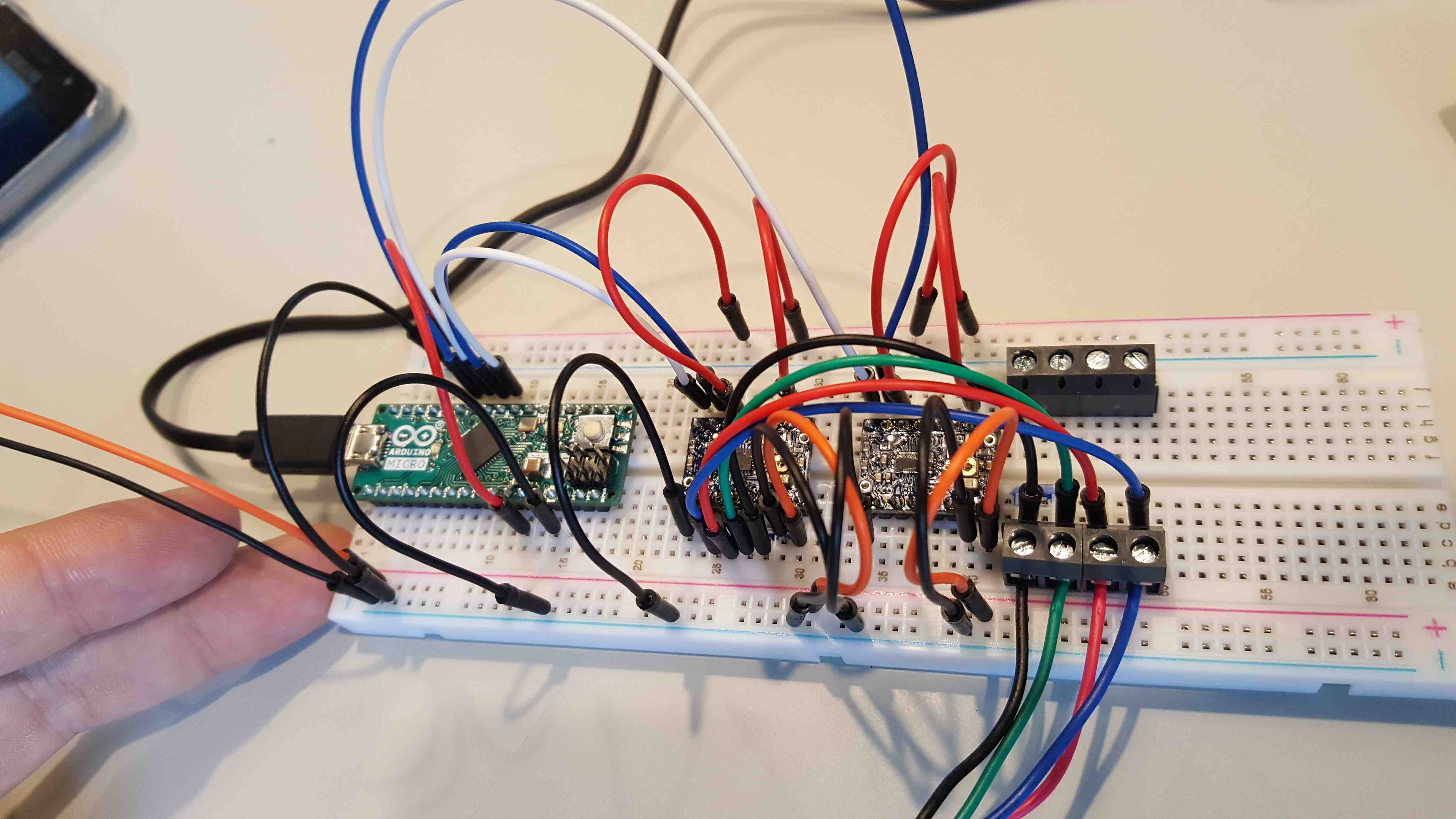
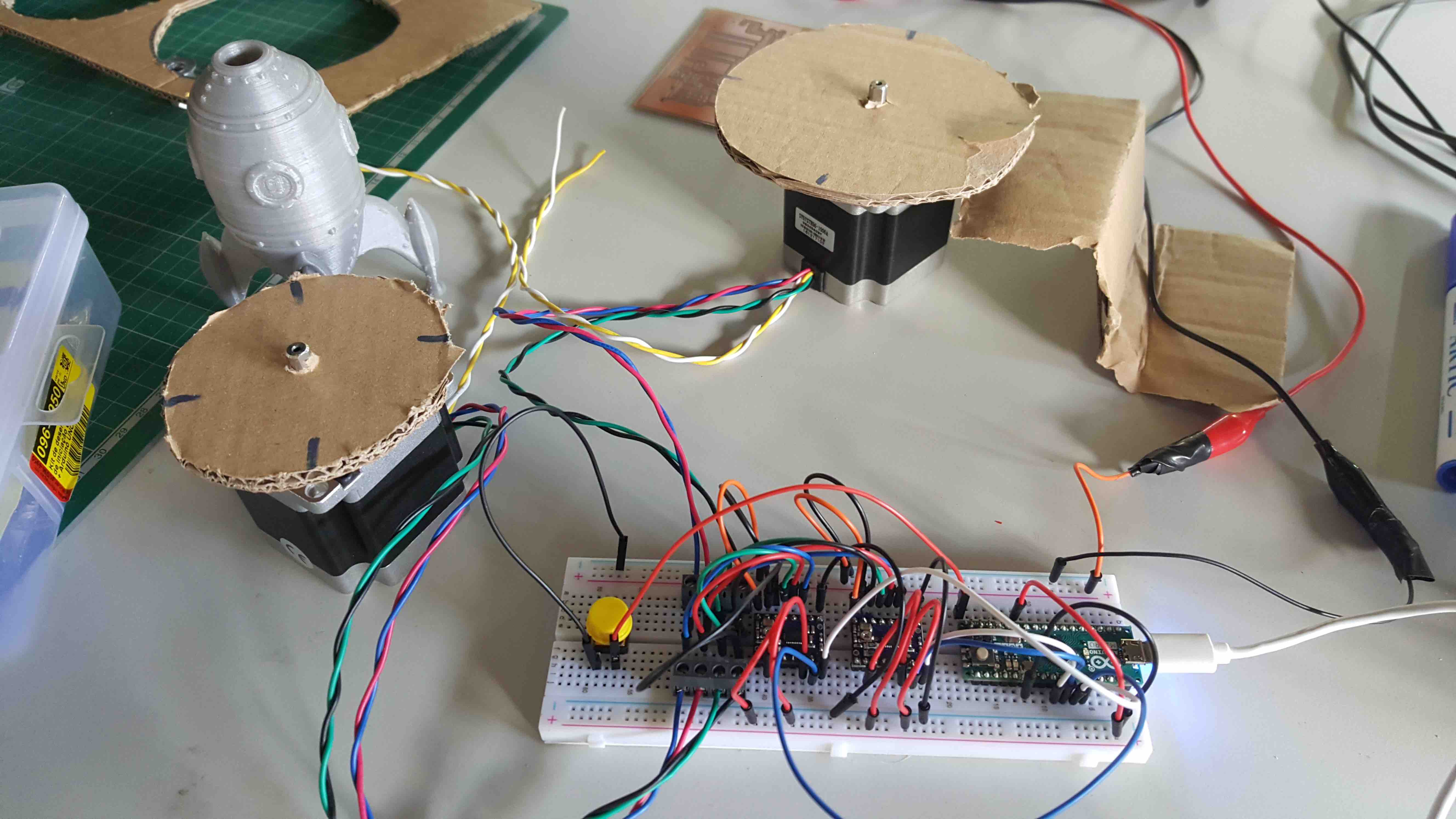
We'd started looking into the OpenScan electronics, assembled the components in a breadboard so that the coding could start....
The OpenScan Hardware setup:
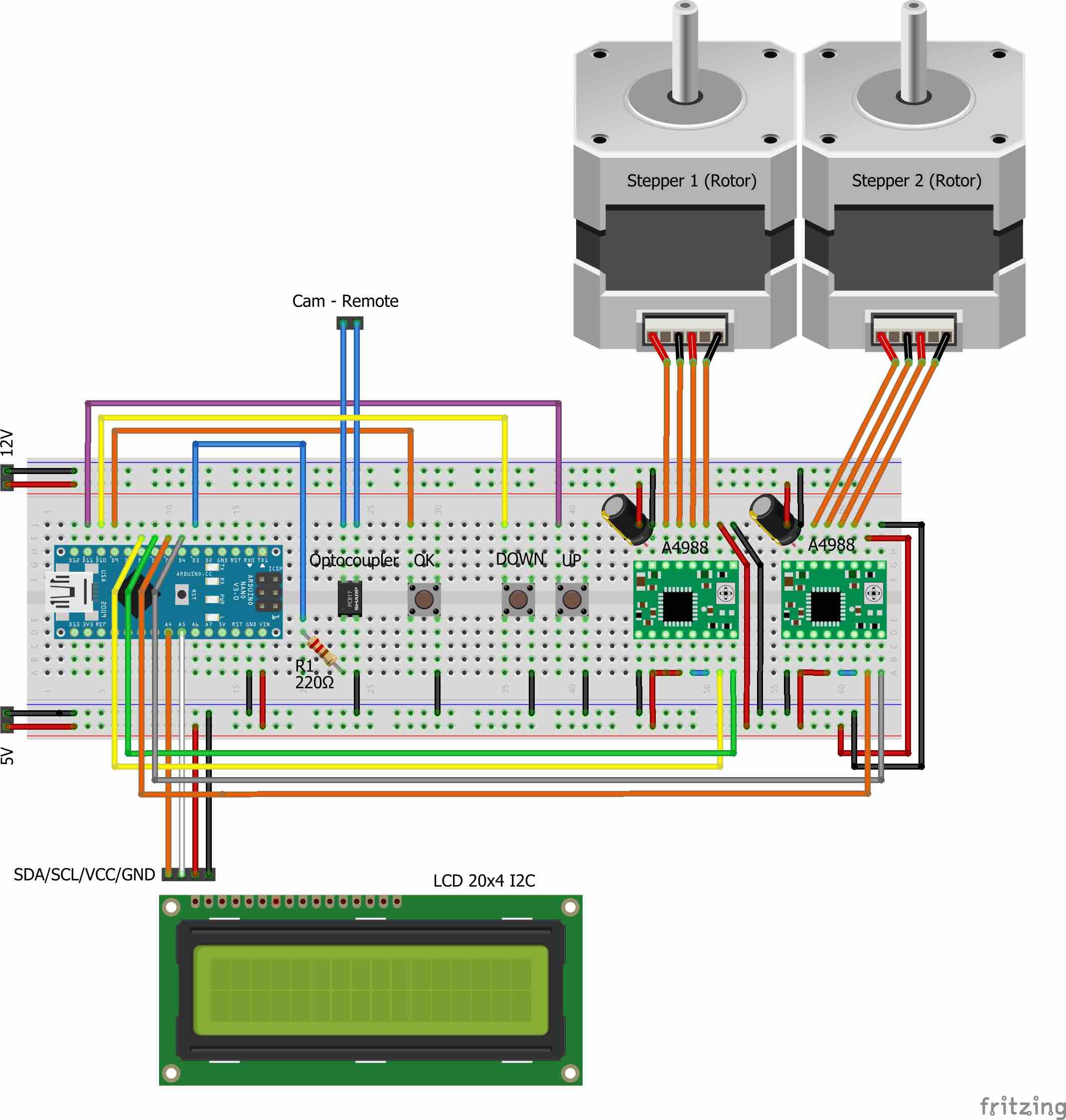
But we need to make some adjustments due to the actual FCT FabLab Inventory, namely:
we had not all this components, but instead we'd to make some adaptations, such as related to local inventory.
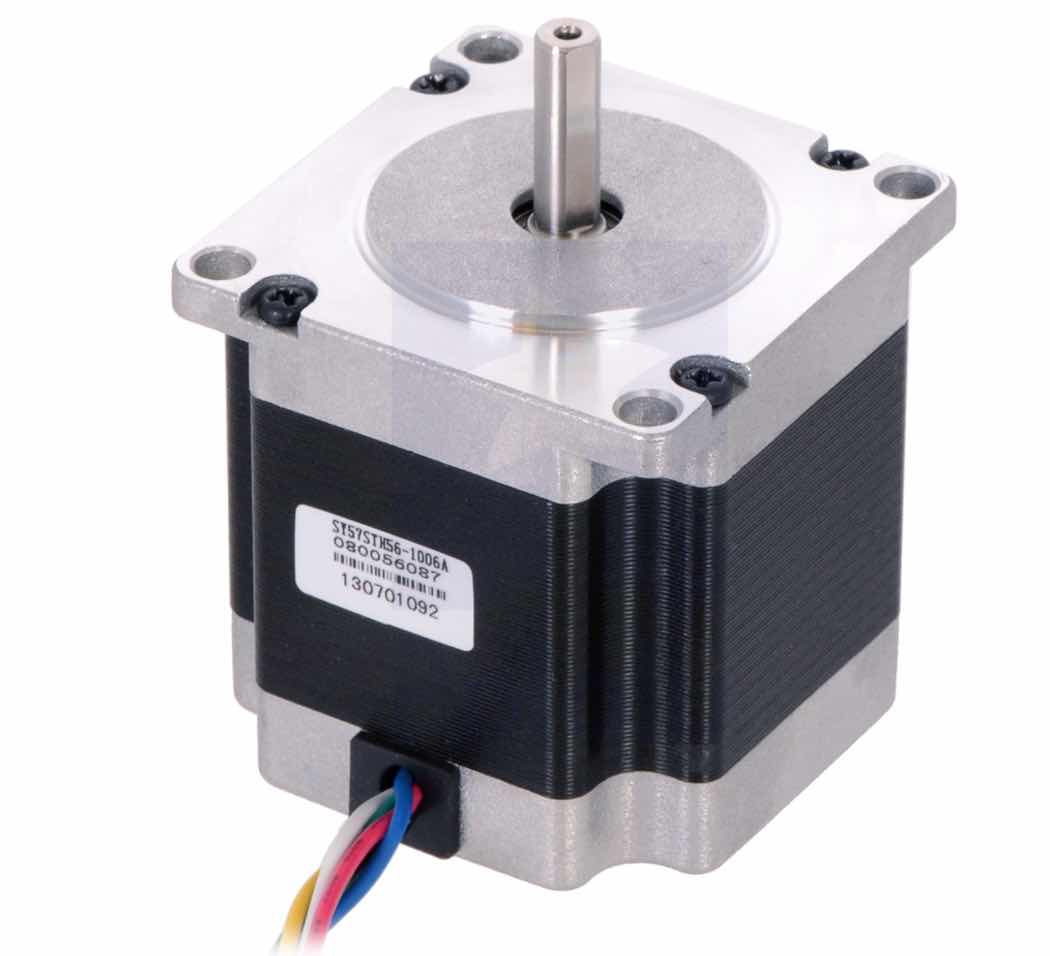
So we discovered 2 equal stepper Motors but running at 7.4V and consuming 1A, so the proposed Drivers (A499) where not adequate since they provide a motor power supply of 8-35V), too much for the 7V found....
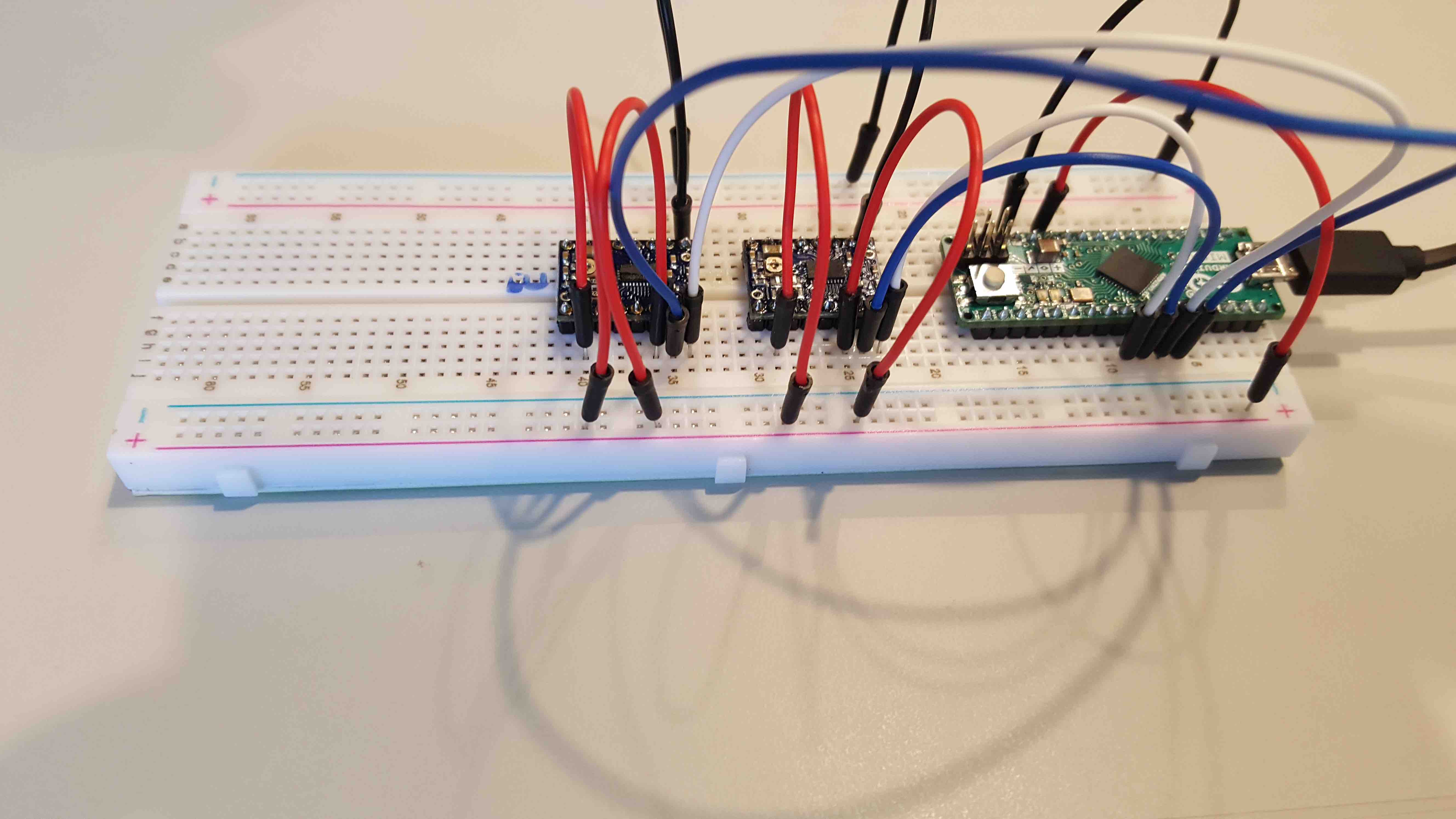
Here's the breadboarding goin on
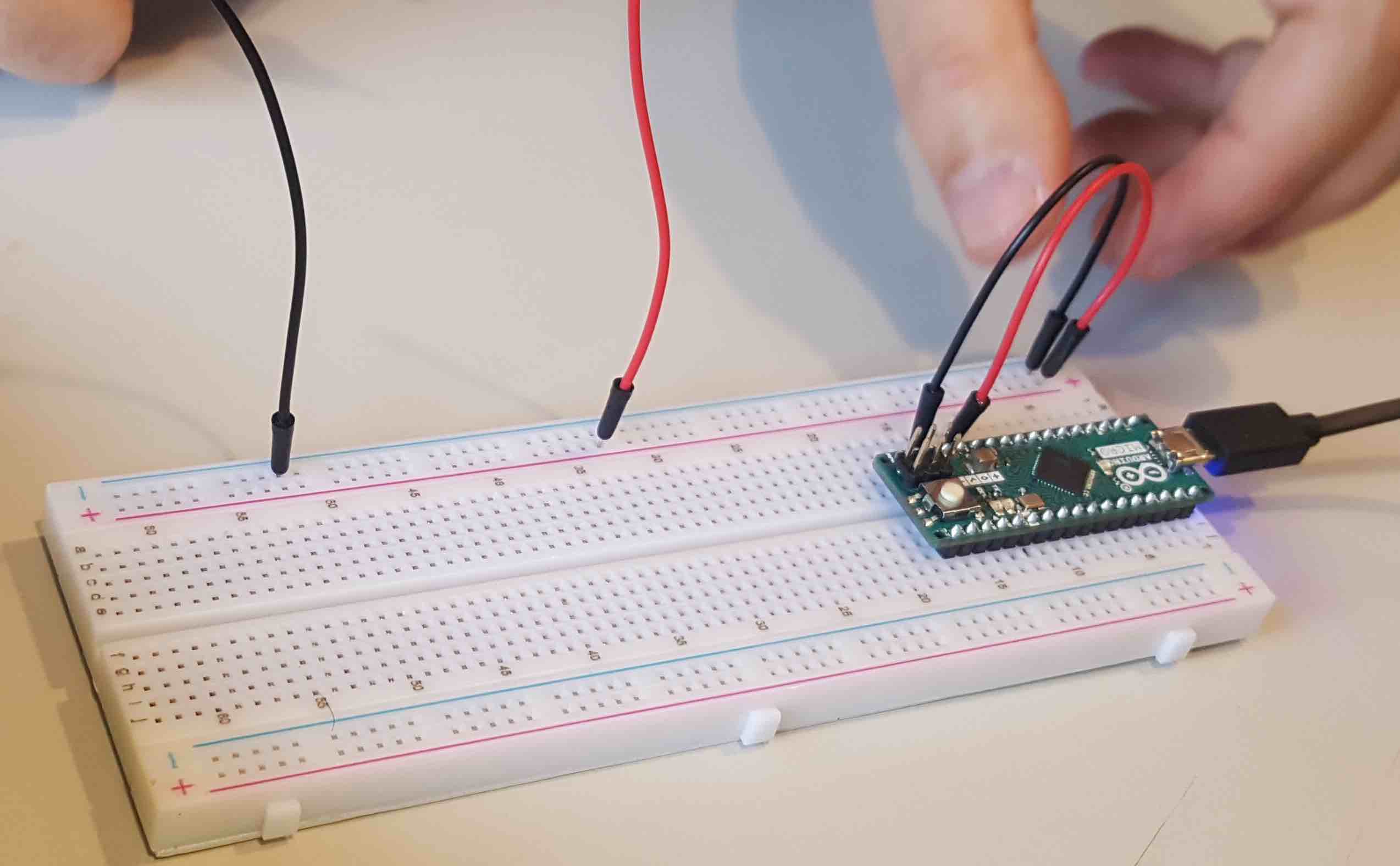 |
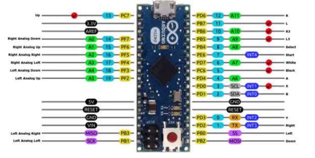
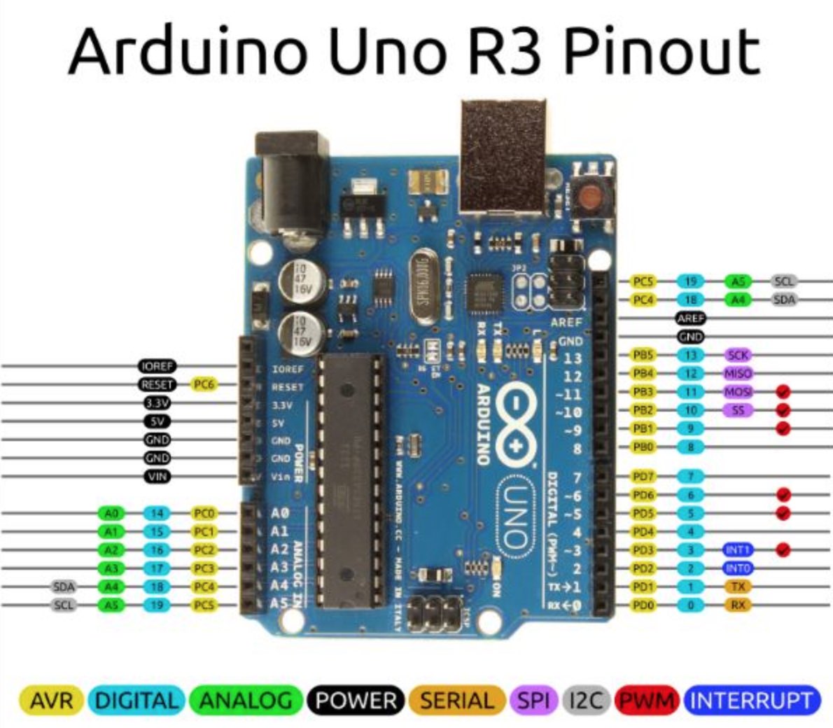
First the Arduino Micro wired to:
|
 |
|
  |
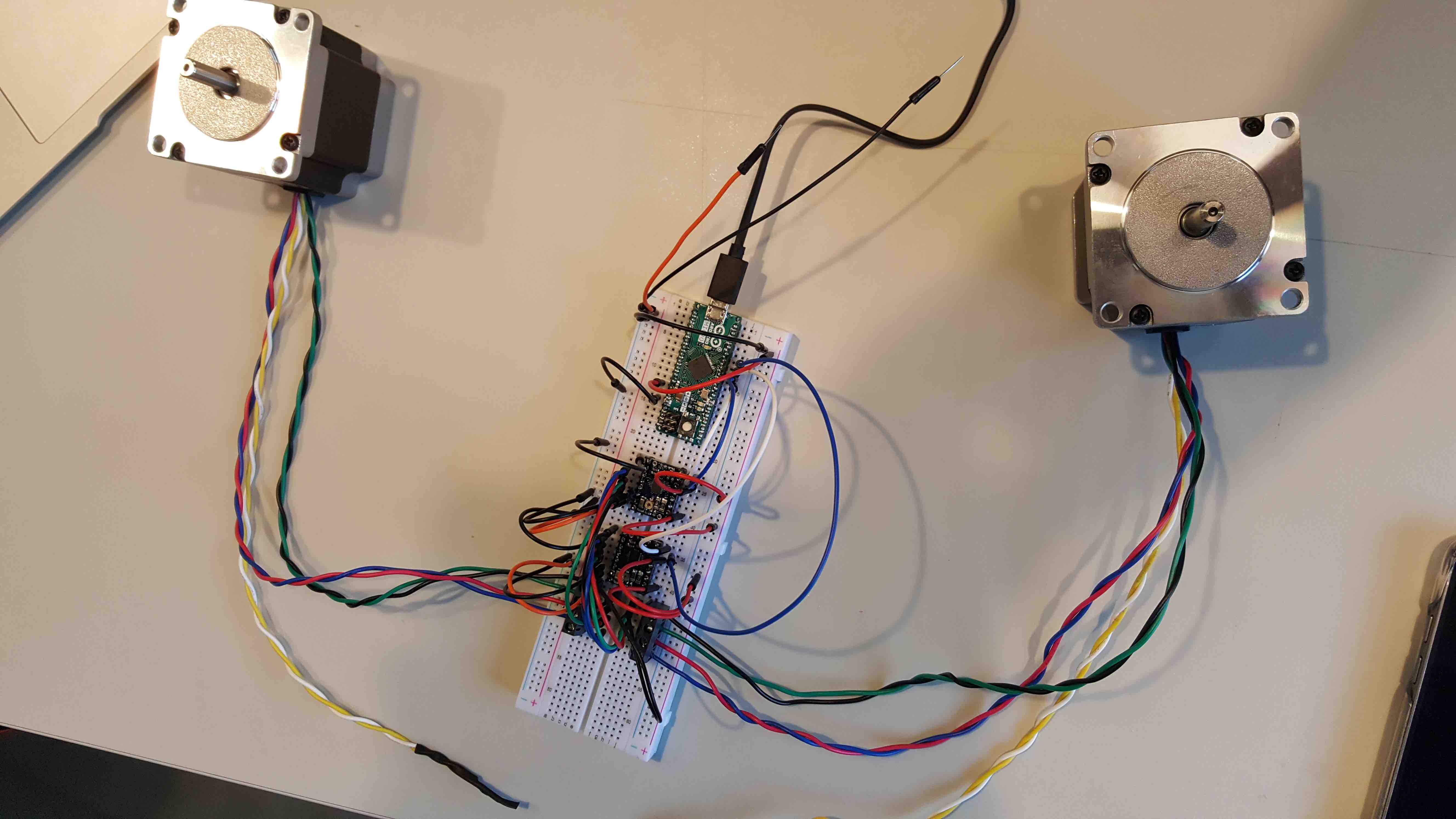
We'll use only the Stepper and DIR of each of the 2 coils, so we organized each Stepper Motor as follows:
|
 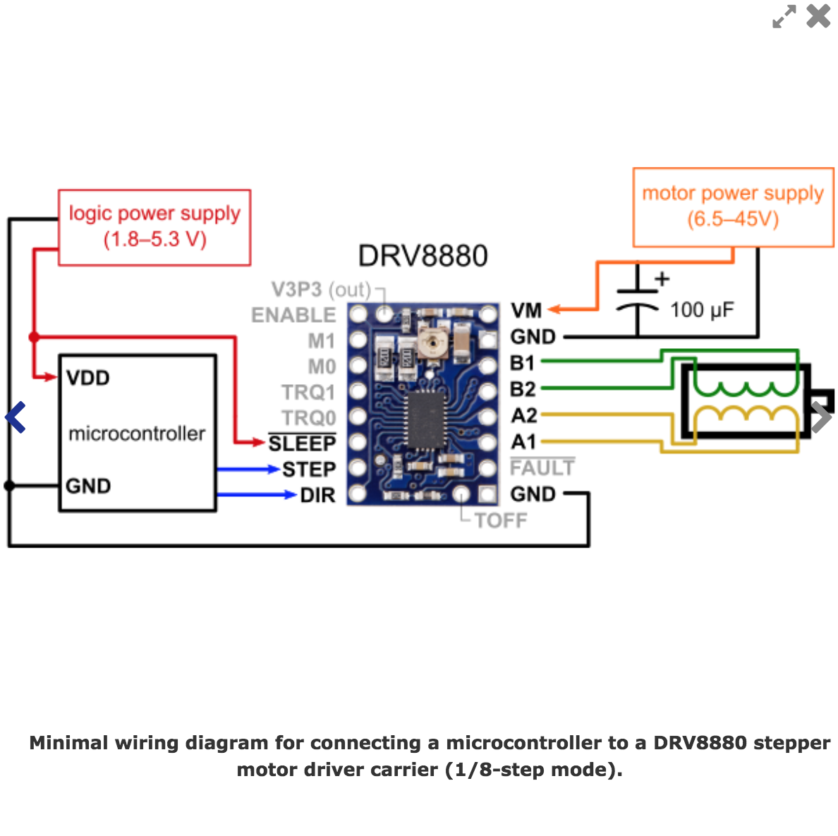 |
Finaly each of the Driver 4 pins to the corresponding Coil Pins
|
 |
And the DRiver VM to Breadbord V coming from Power supply. |
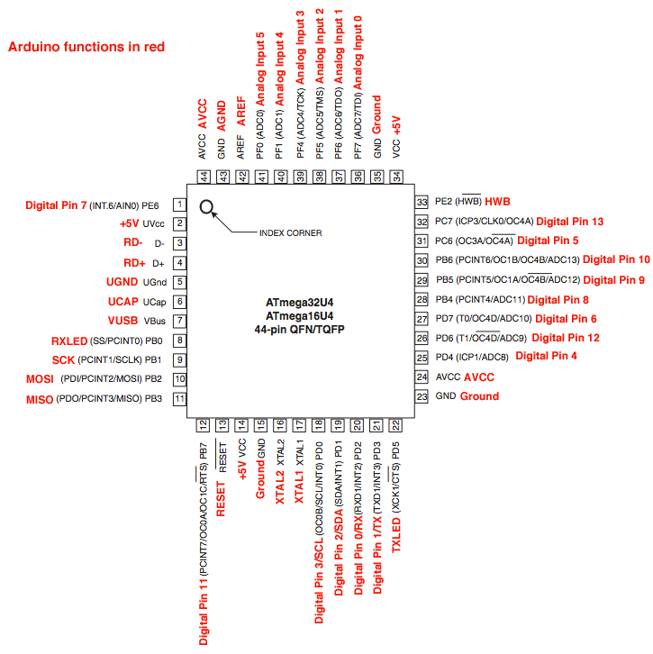
based on the ATmega32U4 featuring a built-in USB
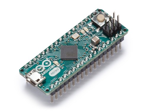
Main Specs:
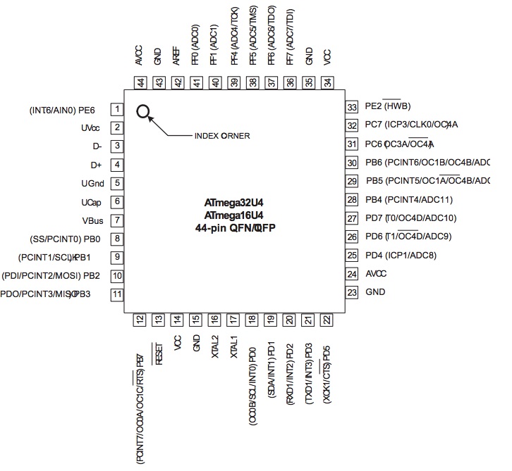 Data Sheet
Need to know how the relation between them....
We'll use the DRV8880 Stepper Motor Driver Carrier
Main Specs:
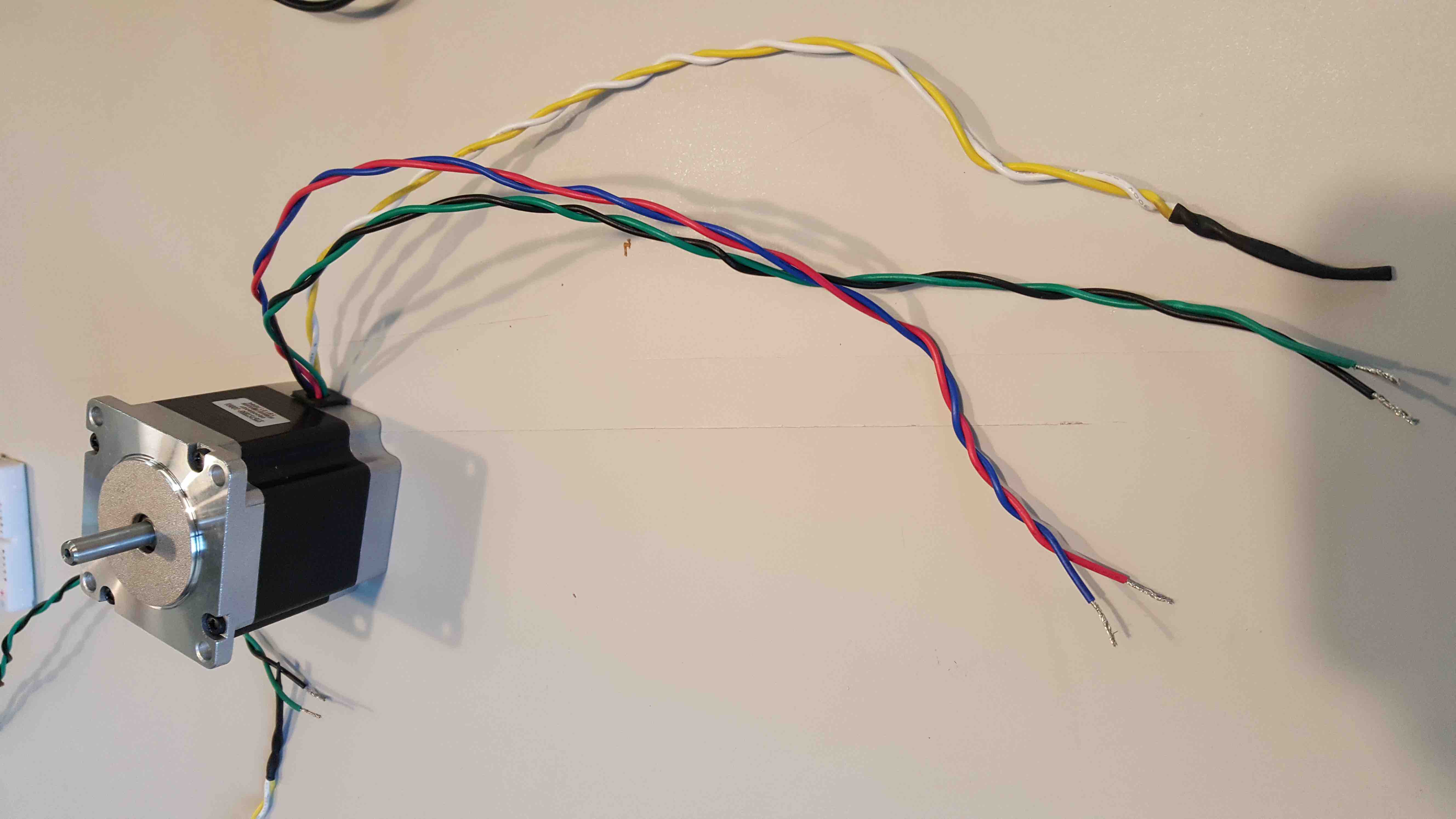
The stepper Motors available in Fab Labs was the a Unipolar/Bipolar 7.4V, 1 A
Main Specs:
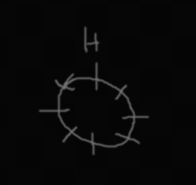
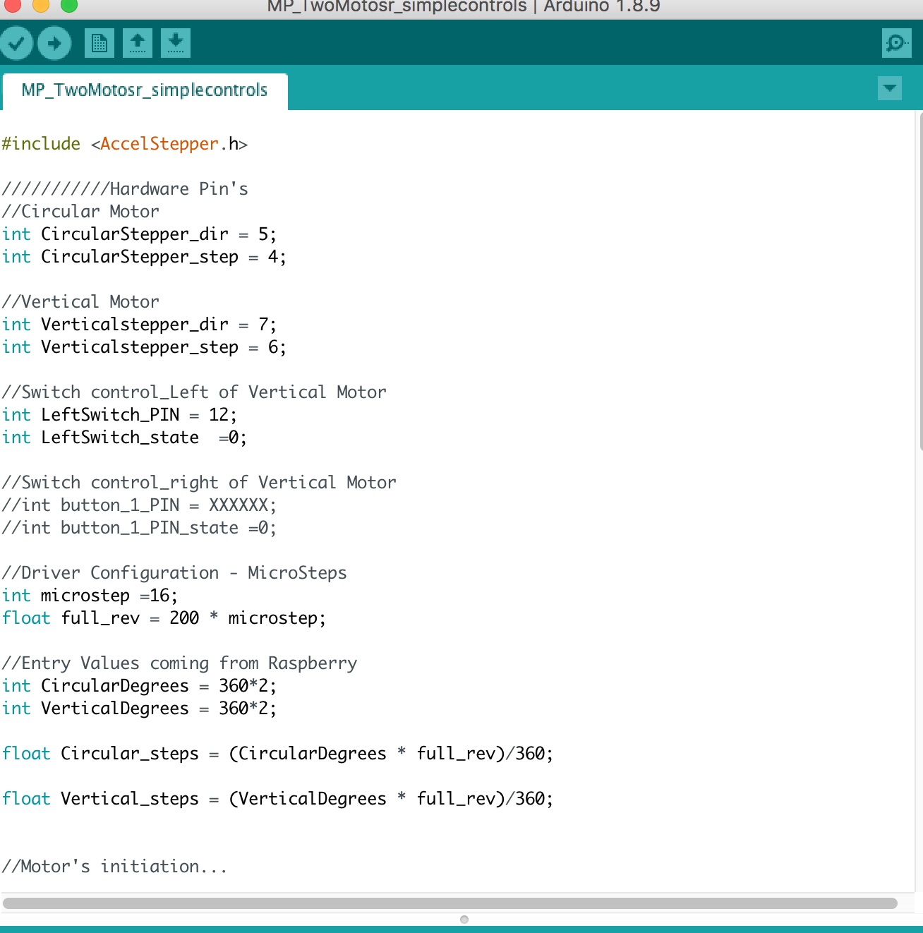
Motor 1 will work as a Plate, so I need to control its movements:
Motor 2 will work as a Harm, so I need to control its movements:

Writing simple and plain code... I's used SublimeText to create the basic code
We'll use the library AccelStepper directly instead of the OpenSCan code...
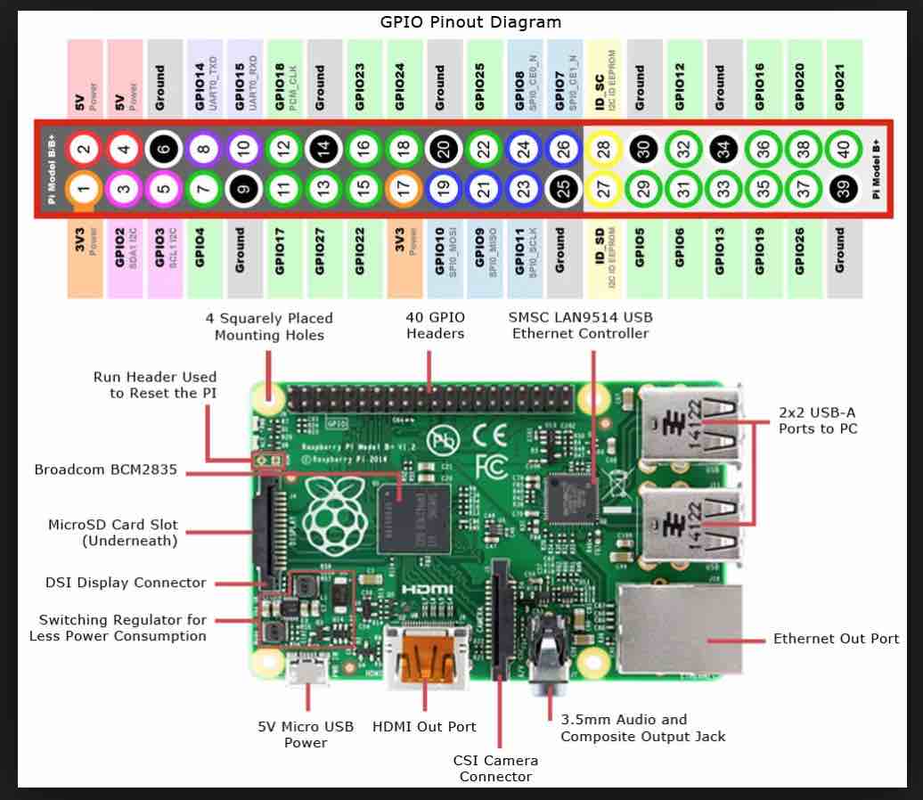
Important Pinouts
The first code to control motor in terms of Degrees...OpenScanMP_Motor1.ino
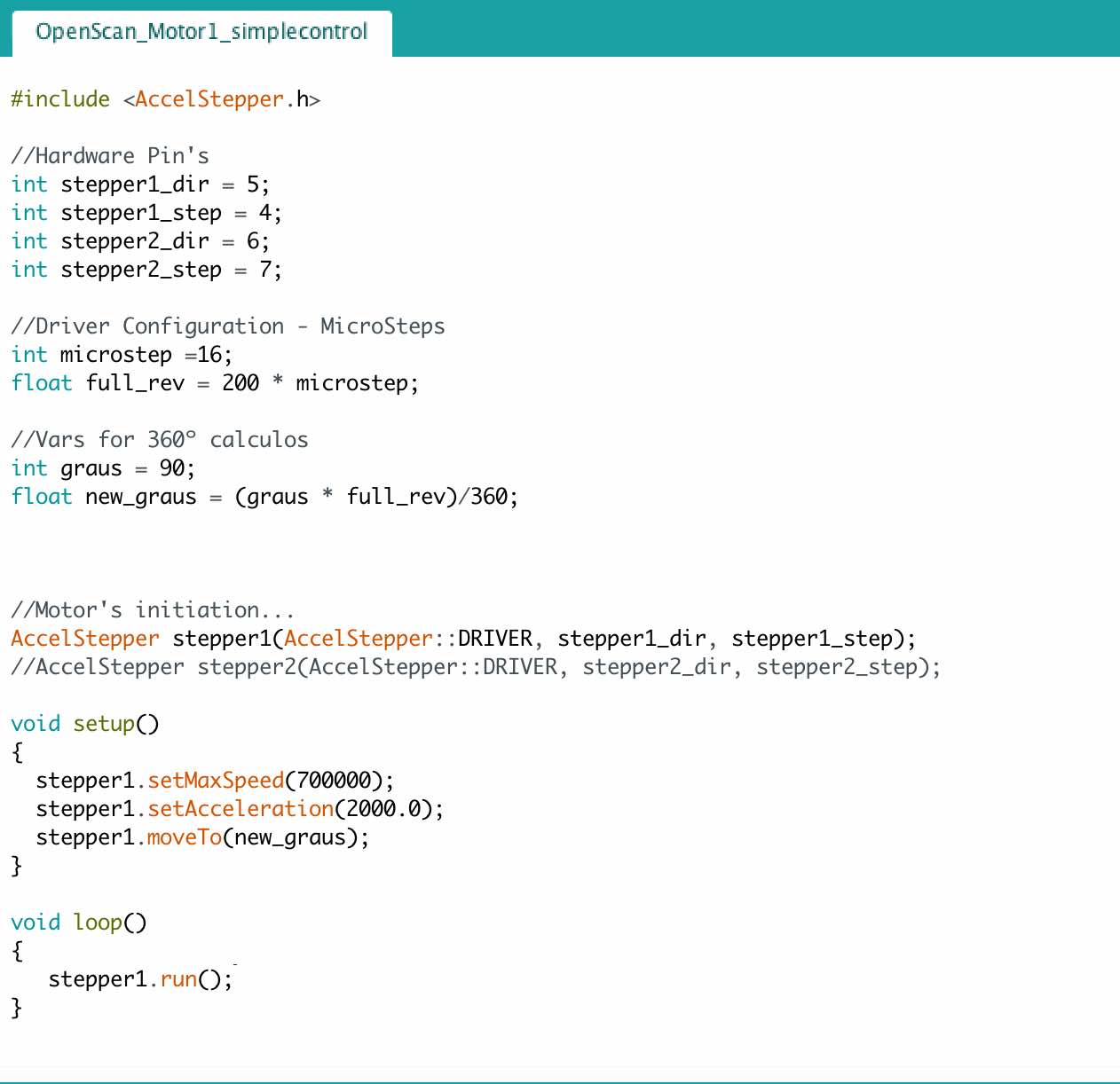
In the above code we defined the movement of 90º as shown in following video
Enables the the read and write on EEPROM (memory whose values are kwpt when the board is turned off (like a tiny hard drive).
Different microcontrollers have different amounts os EEPROM, such as:
Functions:
This library allows you to communicate with I2C / TWI devices.
There are both 7- and 8-bit versions of I2C addresses.
            7 bits identify the device, and the eighth bit determines if it's being written to or read from.
            The Wire library uses 7 bit addresses throughout.
            If you have a datasheet or sample code that uses 8 bit address, you'll want to drop the low bit (i.e. shift the value one bit to the right), yielding an address between 0 and 127.
The Wire library implementation uses a 32 byte buffer, therefore any communication should be within this limit. Exceeding bytes in a single transmission will just be dropped.
But the Microcontroller we'll use has 7-bit I2C addresses
We'll also need to communicate with the RaspberryPi via I2C
Functions:
About interrupts
Interrupts are useful for making things happen automatically in microcontroller programs, and can help solve timing problems. Good tasks for using an interrupt may include reading a rotary encoder, or monitoring user input.
About Interrupt Service Routines
        ISRs are special kinds of functions that have some unique limitations most other functions do not have.
            An ISR cannot have any parameters, and they shouldn’t return anything.
                an ISR should be as short and fast as possible
Nick Gammon’s notes on ATmega328P interrupts
Possible Syntax:
Parameters:
Interrupt Numbers
we should use digitalPinToInterrupt(pin), rather than place an interrupt number directly into your sketch. The specific pins with interrupts, and their mapping to interrupt number varies on each type of board. Direct use of interrupt numbers may seem simple, but it can cause compatibility trouble when your sketch is run on a different board.
Atmega328P External Interrupts
External Interrupts can be configured to trigger on one of 4 states, here is a good documentation
    Re-enables interrupts (after they’ve been disabled by nointerrupts().
        Interrupts allow certain important tasks to happen in the background and are enabled by default.
            Some functions will not work while interrupts are disabled, and incoming communication may be ignored.
                Interrupts can slightly disrupt the timing of code, however, and may be disabled for particularly critical sections of code.
Syntax: interrupts()
    Disables interrupts (you can re-enable them with interrupts()).
        Interrupts allow certain important tasks to happen in the background and are enabled by default.
            Some functions will not work while interrupts are disabled, and incoming communication may be ignored.      Interrupts can slightly disrupt the timing of code, however, and may be disabled for particularly critical sections of code.
Syntax: noInterrupts()
Turns off the given interrupt.
Syntax: detachInterrupt(digitalPinToInterrupt(pin))(recommended)
Syntax: detachInterrupt(interrupt)(not recommended)
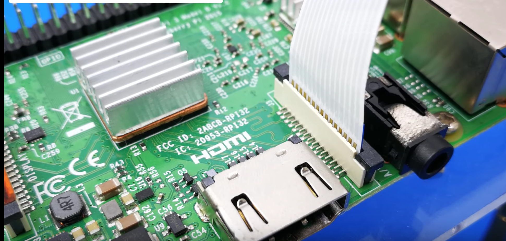
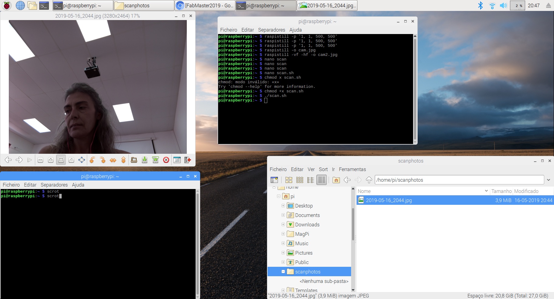
Learning to work with the Raspberry Pi camera...
raspicam commands for Camera:I'll need to take a pictures when a Command is sent from Main board...
take a picture and sabe in a file raspistill -o cam.jpg

but it was upside down.... so to flip it 180º
take a picture and sabe in a file raspistill -vf -hf -o cam2.jpg

Now I need to create a Bash script to take a picture and save it with the timestamp and store it in a folder named scanphotos
I used nano and created a file called scan.sh
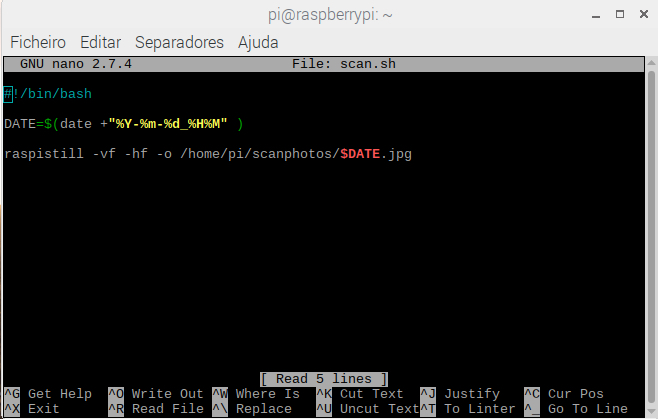
so the comand line sequence is:
nano scan.sh
chmod +x scan.sh
./scan.sh
and here is the picture taken
fundamental whem we miss up with Pi Camera and Camera Preview takes over the screen... with this we can reboot the system...
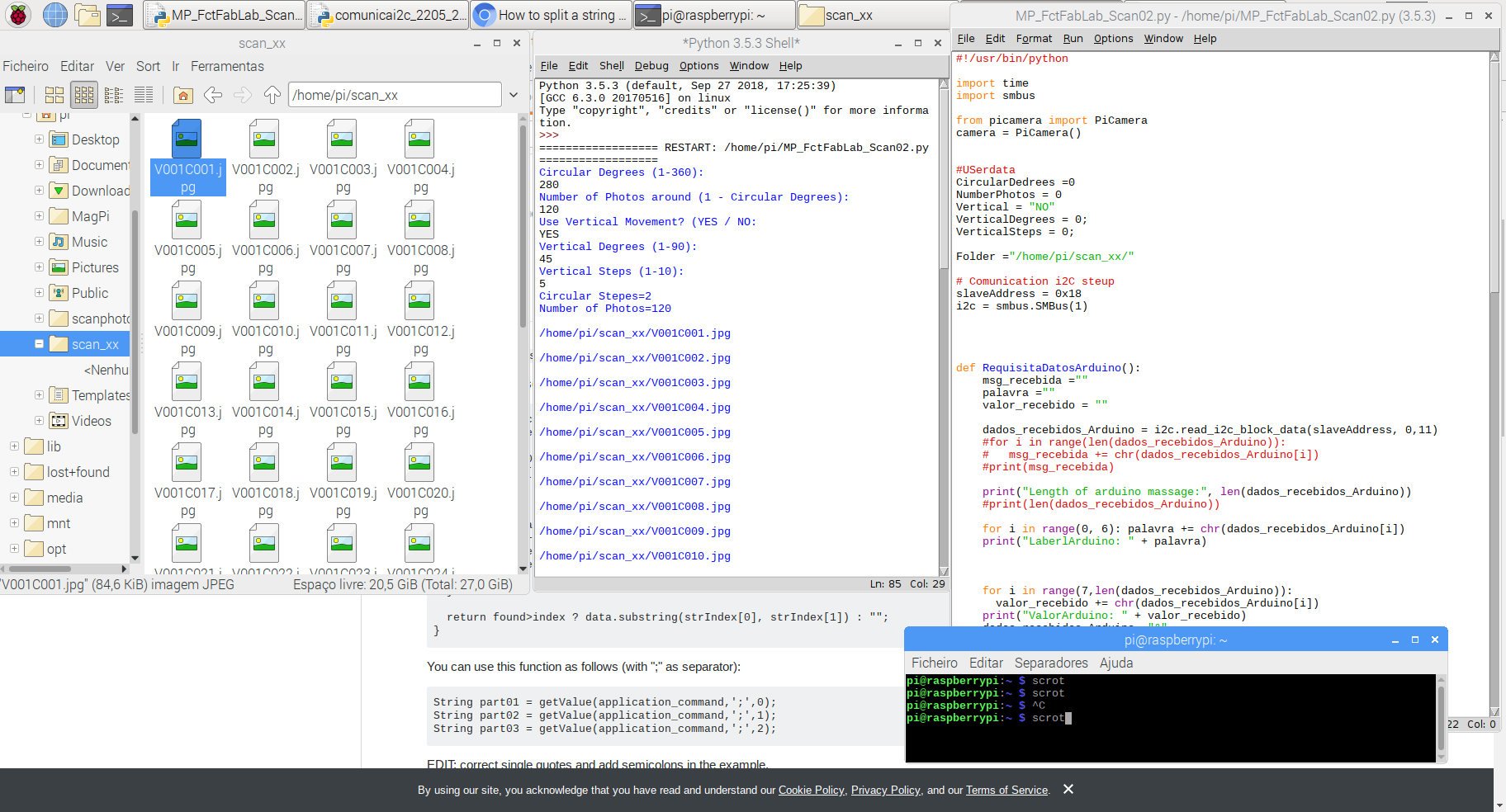
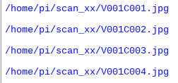
Here is a code that asks the user:
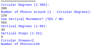
then takes a picture and name it acording to the Circular and Vertical movements
to try-it out onse I'll follow this tutorial from Hackers.io
But the link to the I2C.Py file was broken so I'd to find another, does one: Raspberry-Pi-sample-code/i2c.py
But the link to the I2C.Py file was broken so I'd not beem able to finishe this tutotial...
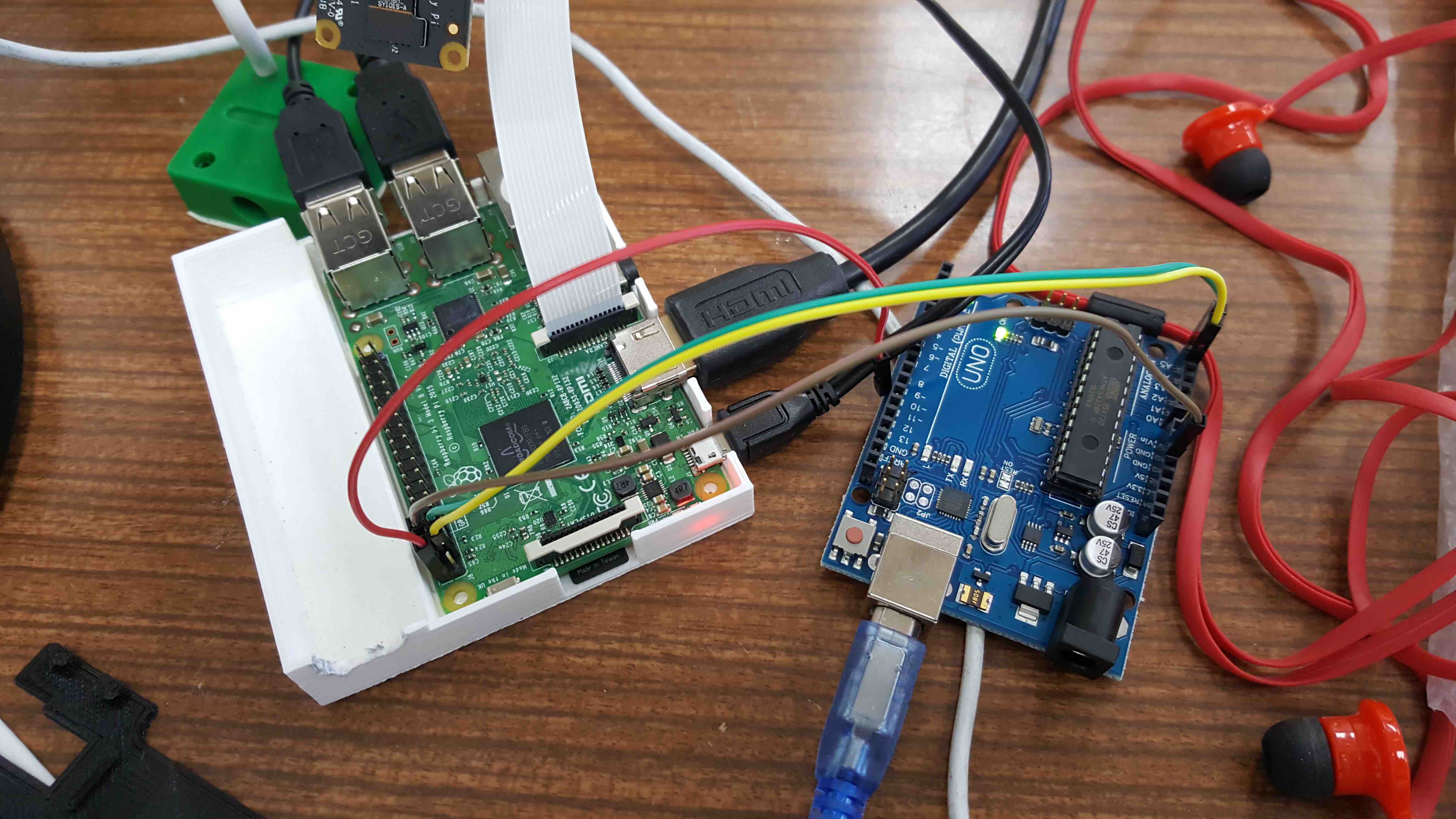
lets try another... raspberry pi and Arduino connected using i2c
Pins:
new concepts learned here:
blacklist: or blockslist is a basic access control mechanism that allows through all elements (email addresses, users, passwords, URLs, IP Addresses, domanin names, files hashes, etc), except those explicitly mentioned. Those itens on the list are denied access. The opposite is a whitelist which means only items on the list are let through whatever gate is being used....
        sudo apt-get install -y python-smbus
        sudo apt-get install -y i2c-tools
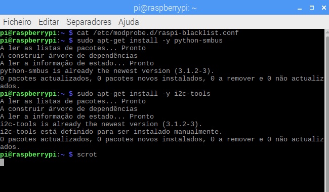
to check if the i2c is installed:
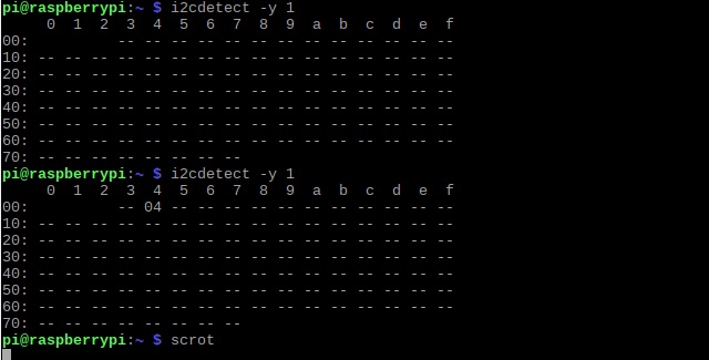
sudo i2cdetect -y 1
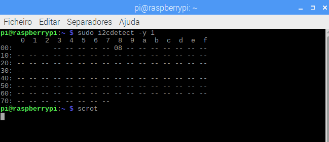
what means this i2cdected output?
        It outputs a table with the list of detected devices on the specified bus.
        Each cell in the output table will contain one of the following symbols:
        "__" the address was probed but no chip answered
        "UU" Probing was skiped, because this address is currently in use by a driver.
        "08" an addresss number in hexadecimal, e.g. "2d". A chip was found at this address...
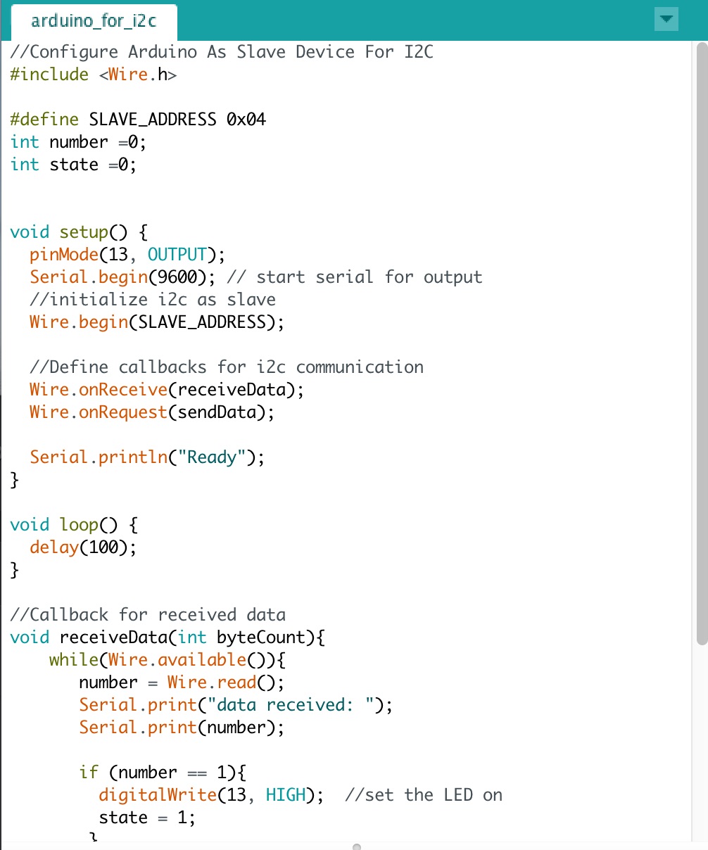 Arduino code DOWNLOAD
Uploaded the scketch and on the Raspberry looked for the IC2....
was working on this code Pyhton code not working... need to look into the provided links...
        sudo apt-get update
        sudo apt-get upgrade
        sudo apt-get dist-upgrade
        sudo apt-get install python-smbus python3-smbus python-dev python3-dev
        sudo apt-get install i2c-tools
I'd looked into many examples and had been hable to receive and divide the String comming from Arduino in RaspberryPi3
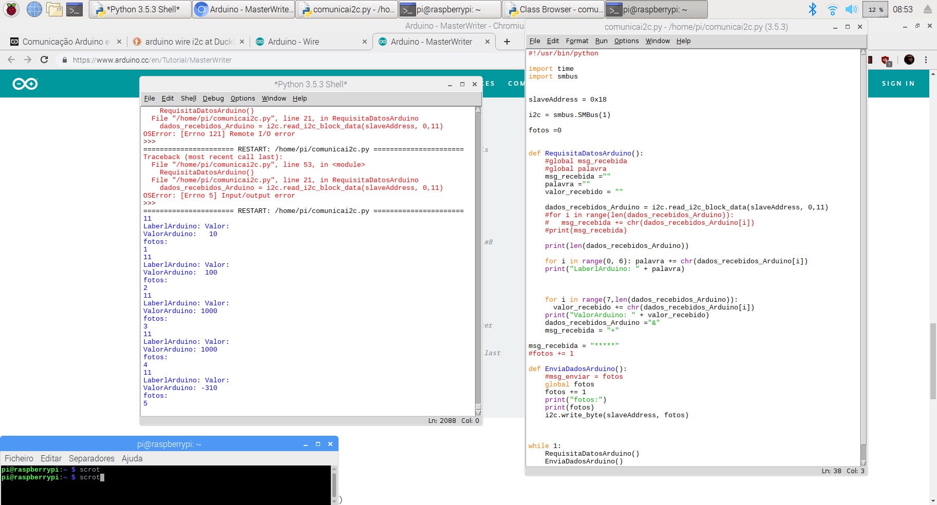
With this code the string sent by Arduino UNO is decomposed into two separate parts, namelly DataLabel and Value
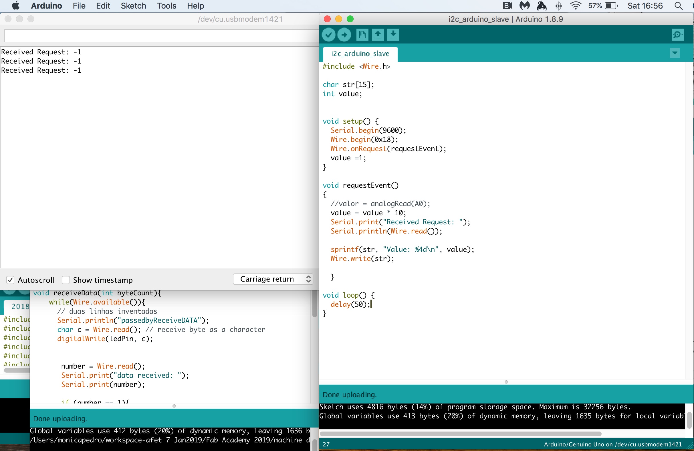
Here I'm receiving the Request, but not able to identify the value, it's not yet a meanfull value...
Raspberry pi will send to Arduino two commands:
to be able to send a meaningful character I'll send the ASCI code of the character which is obtained with the Python function ord()
i2c.write_byte(slaveaddress, ord("x"))
So in the side of Arduino I'll need to converte the ASCI code of each character (coming in each byte) into a string which is obtained with the following block os code:
        int x = Wire.read();
        c= x;                        // previously defined as char c;
        phrase = String(phrase + c); // previously defined as String phrase;
Now the question is how to convert a String into the neaningful numebrs, two integers of 3 digitis each...===?????
sudo apt-get intall rpi.gpio
A Pyhton module to control the GPIO on a Raspberry Pisourceforge.net
The first and and simplest way is to check the input value at a point in time. This is known as "polling" and can potentially miss an input if your program reads the value at the wrong time. Polling is performed in loops and can potentially be processor intensive. The other way os responding to a GPIO input is using "interrups" (edge detection). And edge is the name of a transition from HIGH to LOW (falling edge) or LOW to HIGH (rising edge).
We have a input pin that will bring the signal from two switchs that will detect to the end positions Harm Motor, so to create a Closed loop.
But this input pins does not have hardware pull-ups so we could use RPi.GPIO module that allows to configure the Broadcom SOC to do this in software.
example of code to wait for a button press by pulling in a loop:
        while GPIO.input(channel) == GPIO.LOW:
            time.sleep(0.01) # wait 10 ms to give the CPU chance to do other things...Assuming that pressing the button changes the input from LOW to HIGH
An edge is the change in state of an electrical signal from LOW to HIGH (rising edge) or from HIGH to LOW (falling edge). For us its more important the change in state of the input than it's value. This change in state is an event.
To avoid missing a button press while our program is busy doing something else, there are two ways to get round this:
                    GPIO.add_event_detect(channel, GPIO.RISING)  # add rising edge detection on a channel
                    do_something()
                    if GPIO.event_detected(channel):
                        print('Button pressed')
                    def my_callback(channel):
                        print('This is a edge event callback function!')
                        print('Edge detected on channel %s'%channel)
                        print('This is run in a different thread to your main program')

                    GPIO.add_event_detect(channel, GPIO.RISING, callback=my_callback)  # add rising edge detection on a channel
                    ...the rest of your program...
I'd added a Button on the BreadBoard to have the Hardware needed to create the code, which ideia is to use TWO switchs that will inetrrupt HARM MOtor if they reach them...
Two wires needed:
 Arduino IDE Code Download