
Final Project
Stage 2 - 3D Design and Fabrication
The next stage in the process is to design and manufacture the parts that
go into the camera housing and control. From the planning stage, I need to
- 3D design and manufacture the camera housing
- design, fabricate and construct the electronic control boards
Design & fabrication of camera housing
Using a number of sketches, I decided to break this part of the project into three parts:
- The holder for the camera
- A collar mechanism that connects the motor to the camera holder
- The housing for the motor and control boards
- Camera holder ( prj_camera_base.ipt)
- Motor coupler (prj_motor_collar.ipt)
- Motor housing cover (prj_cover.ipt)
- Motor housing (prj_base.ipt)
- Assembly (prj_assembly.iam) - Exploded view (prj_assembly_exploded.iam)
- RDuino V4, an ATMega328p system (Schematic, Board)
- L298 Dual H-bridge driver (Schematic, Board)
- A4982 Stepper Moter driver (Schematic, Board)
- Eagle CAD working files
(Library of parts used)
(Script file for easy manipulation)
Copy script file to Eagle/SCR folder and rename it to eagle.scr for auto-loading on each project.
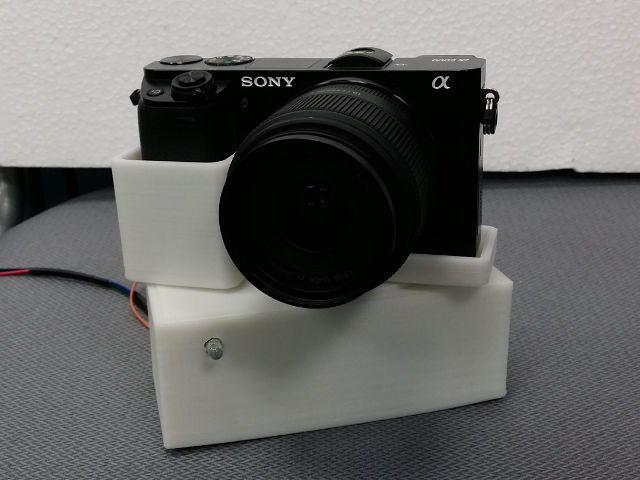
I decided to have a "drop-in" holder for the camera, although there were
many other methods of securing the camera to the motor e.g. Arca-Swiss and
Manfrotto camera plates, having learnt my lesson from previous occassions where
by the time the camera is locked into place, its time to move on.
The camera housing would fit the camera (using a drop-in) with sufficient give to
be locked in place using friction by a felt cloth which would be glued to the inside
of the holder to act as friction holding as well as creating an scratch-resistance
housing for the camera and its screen.
The housing for the motor and circuit boards is simple to produce, which is essentially a box, however, with 3D printing, I could design it in such a way that no screws are need to lock the devices into place. This would rely on the exactness and precision of the 3D printed objects. In any case, I left a +/- 1 mm allowance on all sides of the housing for adjustment. The housing includes the footprint of the motor and the length of the shaft and drive. These could be obtained from the Pololu site which had the exact dimensions and verified using manual measurement.
I consulted Roy regarding the motor coupling and he suggested having a hexagon key cut into the camera holder which is coupled with another hexagon collar that is locked into the motor shaft. I think that this is a brilliant idea and decided to make a collar that fits/locks onto the motor shaft and this in turn drives the camera holder. The camera holder will close-lock-fit with the hexagon providing the necessary friction to drive he holder.
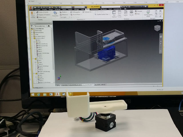
Having these three parts in mind, I set out using AutoCad Inventor to draw the parts with exact dimensioning so as to fit all three components. I later added a fourth part which was the cover for the motor housing. Using the snap fit technique, I gave only 1mm allowances on all sides with the edges to be chamfered for a better fit. The drawing of all four parts and making it fit using Inventor took the better part of 1 day with full fit test
The parts where then individually exported to STL files and 3D printed using ABS plastic. When the parts were done (approximately 8 hrs with 2 3D systems), they were found to be a perfect fit with little allowance. The motor collar was fitted with a 3mm holding screw and the parts could be assembled. There was a little warping on the base of the holder, but other than that all parts looked ok and were ready for use.
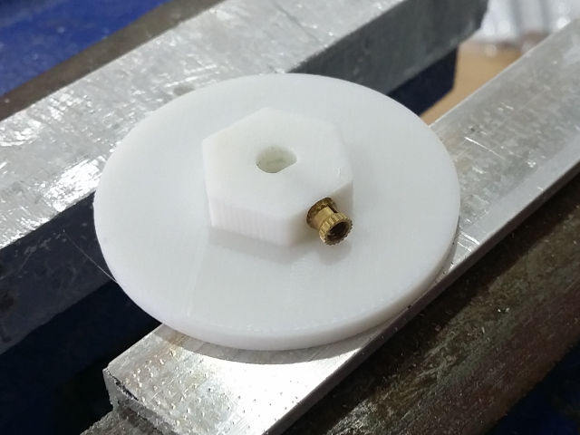
Motor Collar with hexagon key
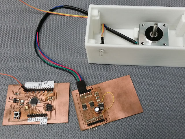
Motor controller
Motor assembly

Complete housing

Component parts
Final Project Prototype

Assembly of project parts

Assembly of project parts - exploded view

Assembly of project parts - exploded view
The following are the inventor files for the different parts of the project and the assembly drawing:
Control System Design and Fabrication
In order to make programming simpler, I decided to create my own ATMega328p
board to use within the Arduino IDE system. This would make programming easier
as I have full use of the libraries and the code store. I can also make the
testing easier as I am able to verify the program with any arduino uno board.
In order to do this I had already started on a number of versions of my RDuino boards
using the ATMega328p but incorporating a AVRISP and bringing out all of the I/O pins.
Also in the design was the use of a 16MHz resonator, which would make the board
use the default fuse settings of the Uno system.
The schematic and board layouts are included at the end of this document.
I also decided to build a dual h-bridge board using the L298N and the LM2940 for the conversion of VMotor to Vcc to have a single supply on the board. The layout of the components required a single jumper. The schematics, board and test results are included at the end.
When performing the board tests, our Guru, Steven, discussed the project and we felt that the ATMega328p might be an overkill in the number of I/O pins, so I decided to use an ATTiny84 for the second iteration (time permitting). In this case, I also decided to build an L4982 stepper motor driver board in order to save on the number of I/O pins. As I could not decide on the stepping method to use, I decided to put in a jumper block to allow the user to select the type of micro-stepping if required. The design of the board incorporates the LM2940 and a number of extra GND pins for easier interfacing. The schematics, board and test results are included at the end.
The boards were then cut using the China Mill system, using isolation cut and the components soldered into place. In working with the L/LM-series of power ICs, we have to be careful of the placement of the routes as most of these ICs have a thermal pad underneath. In earlier projects (about 15 years ago), we used to place mica sheets for thermal dissapation, however, these are un-heard off by many of the electronics retail outlets I have visited. So, we compromise by not using the base of the IC for routes and place a ground plane there.
Schematics and Board layouts
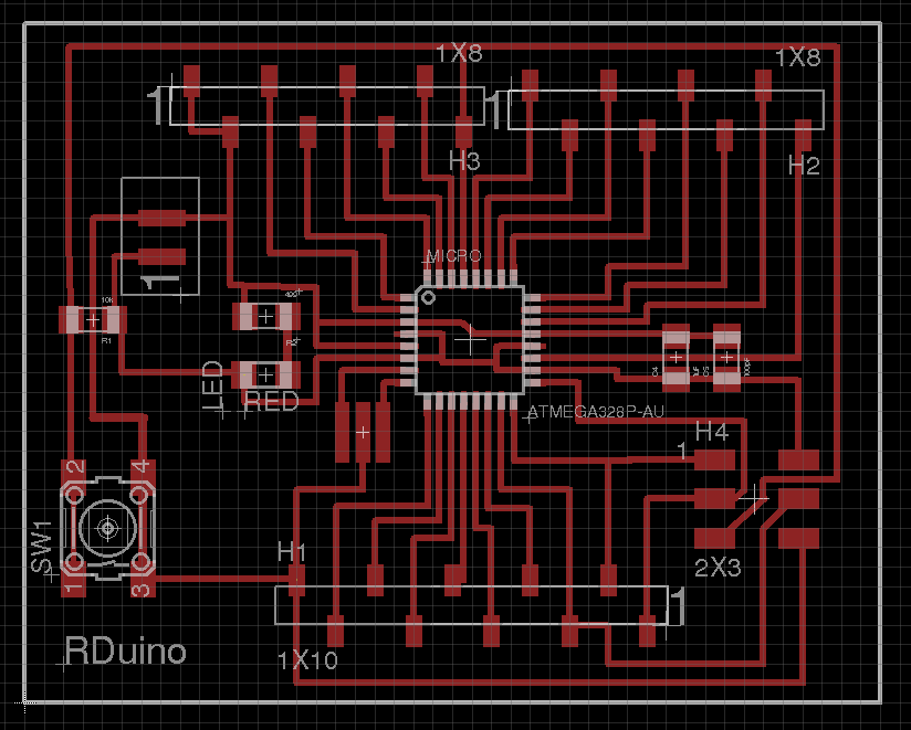
RDuino v4

RDuino ATMega328p
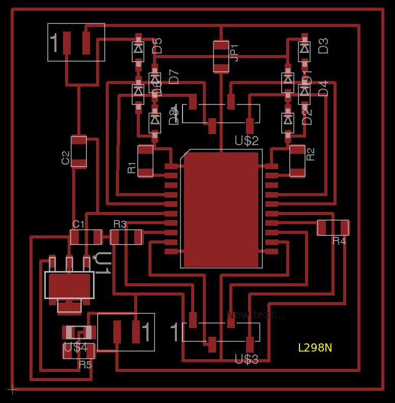
L298N Dual H-bridge

A4982 Stepper Motor Driver
Topics
Not being of a artistic mind, I have shamelessly borrowed this template (simpleStyle_8) from html5webtemplates, in recognition of a simple, cool and functional webpage design.