Final Project
Stage 1 - Planning & Resource Management

My final project is to build an automated panoramic photo taker for
the Sony a6000 camera.
The Sony a6000 has the capability of taking a seamless 12,000x1,800 photo by
pressing the shutter and panning the camera from left to right. However, not
every photograph is a success as the pan depends on
- smooth movement from left-to-right
- sufficient angle change in the photo field
- timing, and
- simultaneously depressing the shutter
I have broken down the project into three stages, and have allocated a
maximum of 4 days for each section of the project, the three stages
are as follows:
- Planning and research into development parts
- Design & Construction of component parts
- Testing & and development
The project construction can be broken down into the following sub-stages:
- The electronics/control section, comprising of
- Triggering the shutter
- Timing of the shutter for the exposure
- Control of a stepper motor for the pan control
- Control of system
- The housing for the camera and motor
Triggering the shutter
The Sony a6000 can be remotely triggered using either Infra-red, a wired remote mechanical/electrical proprietory trigger, or a wireless app (just released) by Sony. I decided to use either the mechanical remote control (1st choice), followed by the infra-red remote.
The mechanical shutter is a micro-USB interface, sold on E-Bay and by Sony
which also included an intervalometer which allows for time-lapse and other
time-controlled exposures.
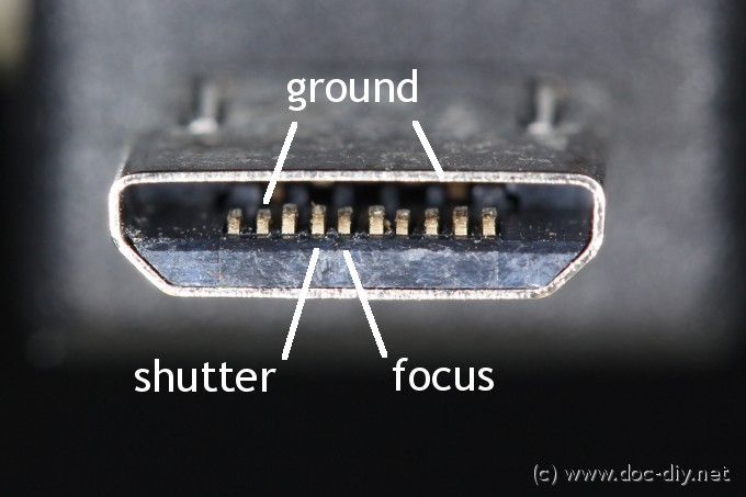
Unfortunately, after doing some research before plugging in a micro-usb cable,
I discovered that the connector, although, it looked like a micro-usb was a
proprietory multi-way connector having 10-pins instead of 5-pins (see image)
below (Ref:
Doc DIY - Camera Remote Pinout List).
There was a more detailed explanation of the pins in the forum unit, ndicating the uses of some of the pins but no quick solution to the problem.
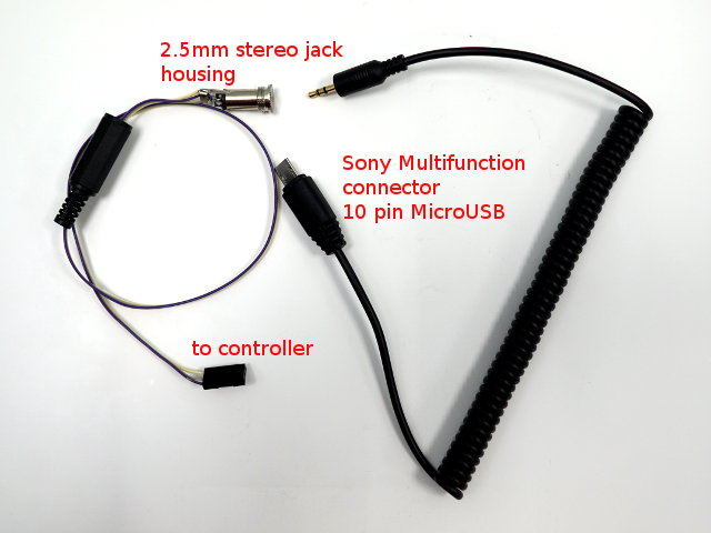
I also managed to obtain a remote trigger release from an eletronic flash
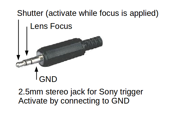
unit which had the same multi-way connector but ended in a 2.5mm stereo jack.
The stereo jack had 3 connections and I thought it would follow some of the
conventions used by other camera manufacturers.
Unfortunately, there is no documentation on the pin use of this cable
and how the triggers work. Since Sony bought over Minolta, I tried some
of the combinations provided by Minolta cameras without avail.
I found out that if I connected the pin case to the center pin, I could trigger
the auto-focus for the lens. Doing the same for the end pin, does not result
in any response.
After 2 hours of work, I decided to call it a day, and had an accidental
movement of the ground signal from the center pin to the end pin and it
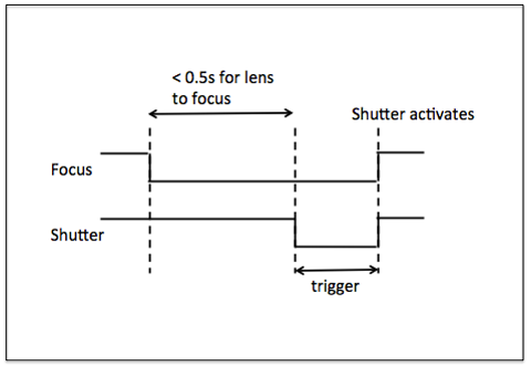
triggered the shutter! The shutter triggers only after the focus is obtained
by the lens, and hence to trigger the signal using the 2.5mm pin, you had to
- Send a signal (GND) to the center pin to focus the lens
- Have a short delay, and with the lens focused (do not remove signal)
- Send a signal (GND) to the end pin to trigger the shutter
On a later Internet search, I found that this is a very common way of focusing and triggering the shutter for other cameras as well, either with a small voltage or with the GND signal.
The next method of triggering the shutter would be to use Infra Red. I had Sony IR Remote which worked with the panorama mode and I thought it would be a neater solution to use a wireless system which can be completely housed in the motor housing. So I first need to read the code sent by the Sony remote for the shutter. For this, I used the reference at SparkFun and Adafruit on the use of IR recievers and sensors.
This resulted an 2 days loss of work, as I encountered one problem after another, which resulted in the following observations:
- Always use new batteries for the devices
- Have more than one remote control (and a known working version) for test
- Have more than one type of reciever (don't trust the chinese ones!)
- Check and double-check the library versions for use with code
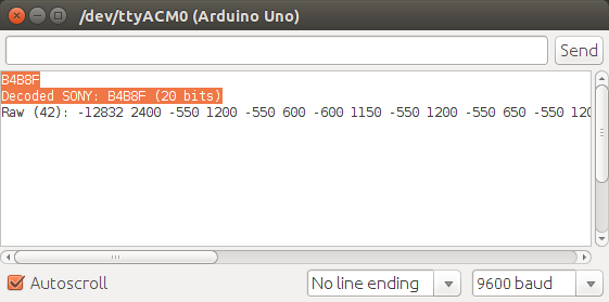
In the end, I found out that the remote was using the Sony encoding and the shutter code was SONY: B4B8F (20 bits). This ended up with the code being simple and boiled down to a single command line irsend.SendSony(0xB4B8F,20).
Receiving & decoding IR signals
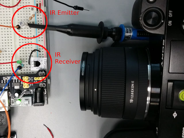
After installing Ken Shirriff's library (updated version, and installed into Arduino IDE), I setup a TSOP382 IR receiver (datasheet) which decodes 38KHz IR signals. The TSOP382 is a 3-pin device which generates TTL signals when receiving and decoding IR signals. I initially connected a LED to the output to indicate that signals were being recieved. The output pin was also connected to PD5 to read and decode the signals.
When the remote control is pressed, I received the coded to be decoded as Sony encoding using 0xB4B8F (20 bits)
Once the code is received and decoded, I modified the IRremote: IRsenddemo to send the code to a Infra Red Emitter Diode (SFH409) to transmit the code. By keeping the LED connected to the IR receiver, I could also detect whether any IR signals were sent with the code.
In this way I could trigger the Sony A6000 to activate the shutter. I then added a push button switch so that I could now trigger the shutter remotely using the microcontroller. However, in order to activate the panoramic mode shutter and mode, the shutter had to be depressed for at least 50 milliseconds and with the camera starting its pan movement. Hence, by trial-and-error, i have obtained a way of triggering the panoramic mode shutter.
The next stage would be to convert the code to be interrupt driven, as we have to handle the movement of the motor to pan the camera in the direction required as well.
Code:
- IRremote: IRrecvDump.ino
Dumps and decodes IR signals from remote sensor (extracted from the Arduino IRremote examples)
Receives IR code from remote, decodes and prints out code information - IRshuttertrig: IRshutterTrig.ino
Waits for pushbutton to send IR code
Waits for the button press, sends IR trigger code repeatedly for 50ms until camera responds with movement for panoramic mode

Camera Transversal System
In order to transverse the camera from left-to-right, I needed a stepper motor so that I could control the amount of rotation. Looking at the prices of stepper motors, they ranged from SGD$30 to SGD$90, so I thought I might try to salvage one for my use from an old hard disk or disk drive. Eventually, I manage to salvage 2 uni-polar and a bipolar motor. I decided to use the bipolar motor as it was the closest to a NEMA-14 Stepper Motor with the specifications closest to what I wanted for the drive system.
I first started building a simple uni-polar stepper motor driver board from the ULN2003 drivers that I had lying around on breadboard, but soon discovered that it had insufficient torque to drive the camera around. I also realised that I had to build a motor driver board that could drive a bi-polar stepper motor as well as needed the correct SMD ICs available to me. Hence the choice boiled down to the following drivers:
- LM298N Dual H-bridge - (DataSheet) - (PyroElectro L298)
- A3967 Easy Stepper Motor Driver - (DataSheet) - (Brian Schmaiz)
- A4988 Stepper Motor Driver Carrier
- (Datasheet)
- (Pololu)
Upon examination of the getstalt boards, I found that the Gestalt 086-005 board also uses a A4982 (A4988 replacement) and decided to base one of the designs on that board.
- (Datasheet) - (Ref IMoyer 086-005)
The advantage of using the L298N Dual H-bridge was that we had plenty of those ICs lying around. Also, this is a traditional DC/stepper motor driver design and is used in countless projects. We could also use the code from one of the classes which involved the driving of a uni-polar stepper motor. The code is a simple one in which we keep track of the motor steps and values applied to the coils and dependent on which way you want the motor to move, you would then send the appropriate motor settings
Stepper Motor code: 8-step stepper motor driver code ( fp_StepperMotorRaw.ino)
The A3967 / A4982 drivers are equally simple to use. All we have to do is to pump
in the steps (in the form of a square wave) and select the direction to turn. The speed
of the motor is controlled by the frequency of the square wave. The torque of the motor
is controlled by a variable trimmer. By changing this value (Vref) you could change the
amount of current supplied to the motor, thereby changing the torque.
An added feature of using the A3867/A4988 is the control of the microstepping through
the MS1 and MS2 inputs. By changing the logic states, you could change the steps from
full, half, quarter or eighths, thereby giving more flexibility in the control of the
stepper motor.
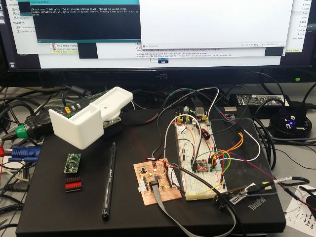
After testing, I decided to build one board of each kind to determine the better one to use for the project


Topics

Not being of a artistic mind, I have shamelessly borrowed this template (simpleStyle_8) from html5webtemplates, in recognition of a simple, cool and functional webpage design.

