W05│ Electronics Production
Individual Assignment: Make an in-circuit programmer by milling the PCB
Group Assignment: Characterizing the specifications of PCB production process
1. Individual Assigment.
This week the assignmet is to make an in-circuit programmer by milling the PCB.
MILLING
In Fab LAb Tecsup we are using a
Step One
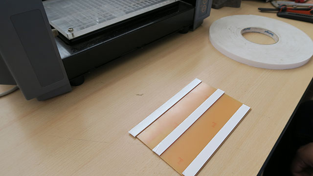
To start with the process I secure the board with double side tape to avoid from moving during the milling.
Step Two
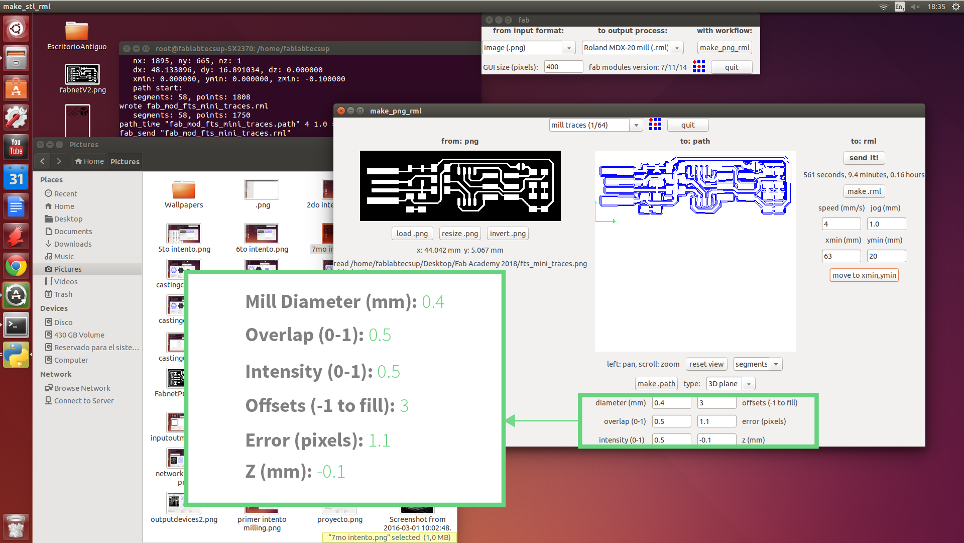
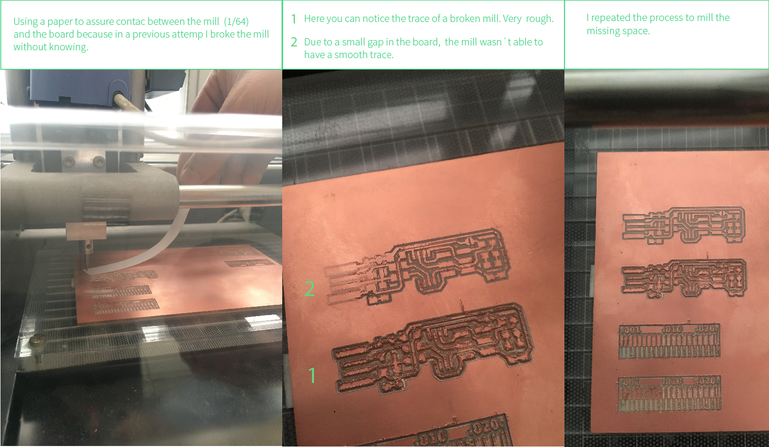
a. I upload the board trace to the Fab Module and the set up the milling path. b.Mill trace selection = 1/64.c. Set up used:
Step Three
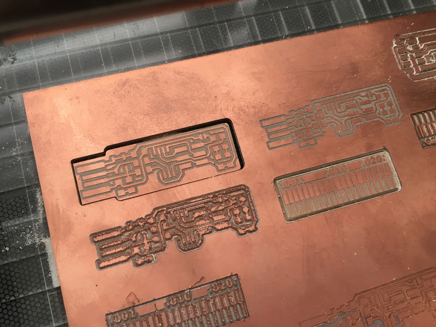
Cut out process: a. Upload
WELDING
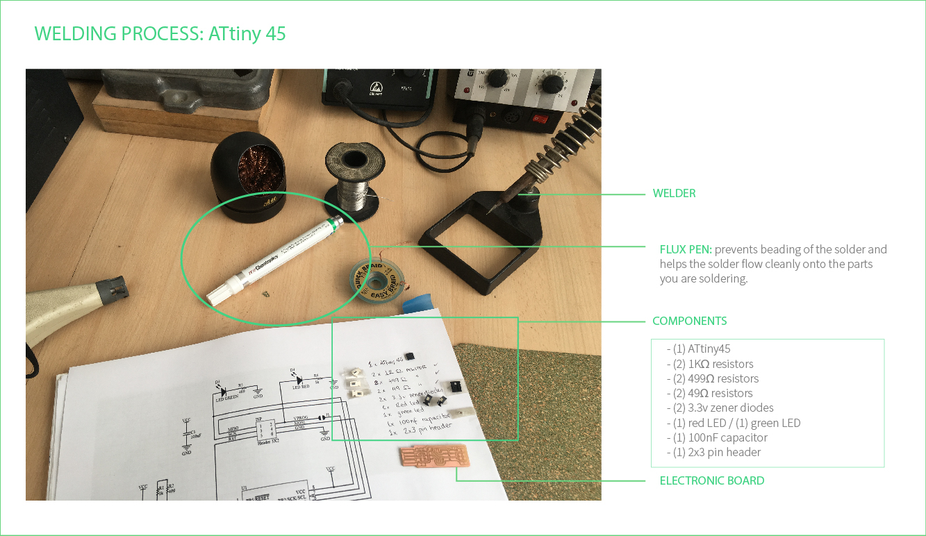
It was my first time at welding this kind of components, so i practice a little bit with old boards. To be honest completly I thought it will be harder but, thanks to the previous experience I had by welding jewelry, was easy to get used to the workflow.
Before starting, it is important to make a list of the components and make a reference to the layout, it will allow you to work fluently.
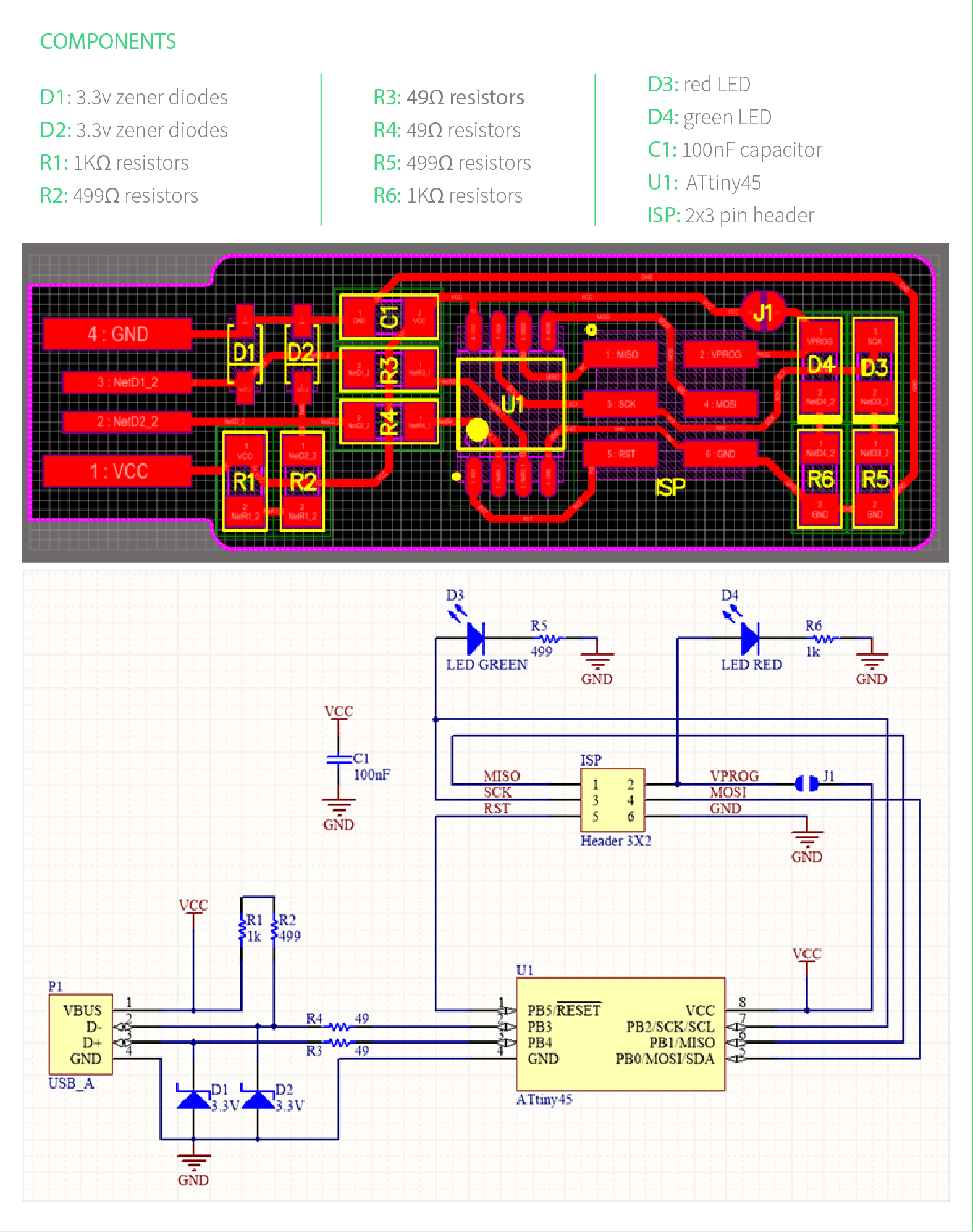
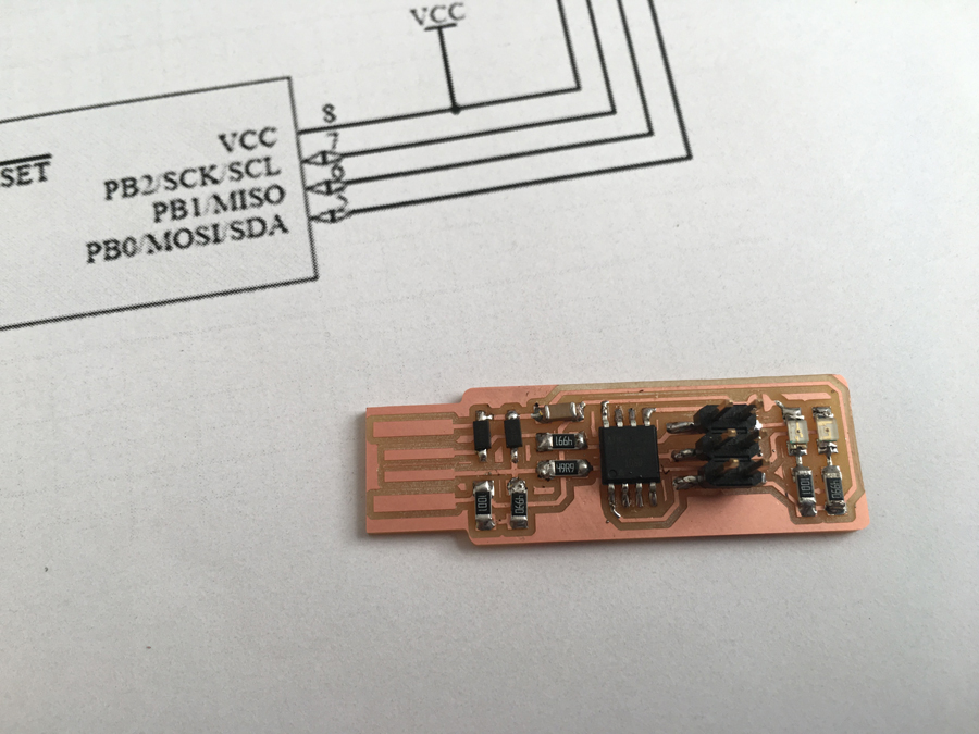
I soldered the parts to the PCB, using the schematic and board image below as a reference for component values and placement.
SOFTWARE INSTALLATION
In order to program the Firmware on my board I followed
Step One
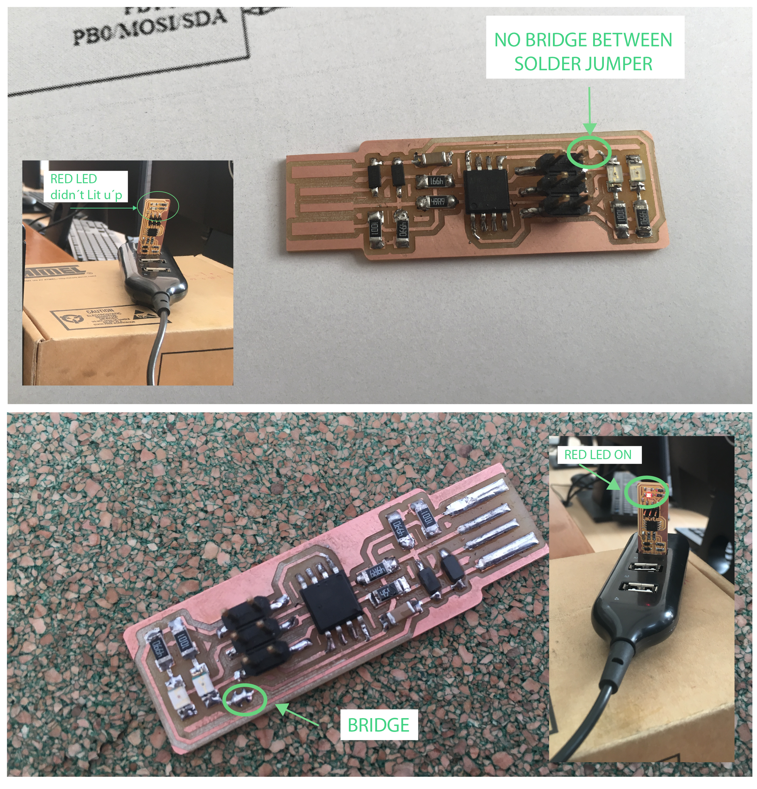
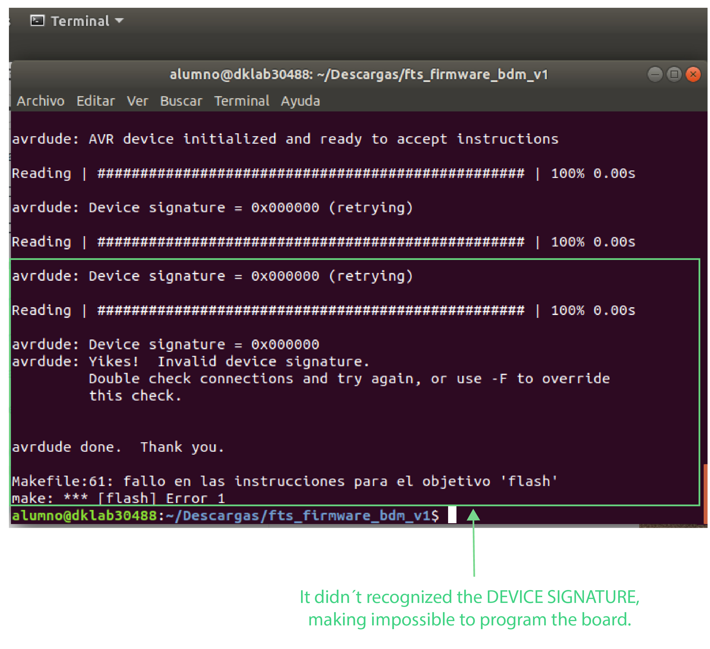
1. VERIFY the programmer is connected correctly and pin 1 on the connector matches up to pin 1 on the board (It was OK).2.Check if the ATtiny45 is installed in the correct orientation, I even welded a new one.3. I use a multimeter to verify that there was continuity between the pins on the chip and the ISP header.4. This part helped me to notice that I was using a wrong resistor (499 instead of 49), remember to always double check the componnets with a magnifying glass.
Even thought i followed all the tutorial steps, nothing seemed to work. Daniel, who works at Fab Lab Tesup and he´s also my Master Jedi, explain me that the ATtiny wasn´t communicating with the computer due to its

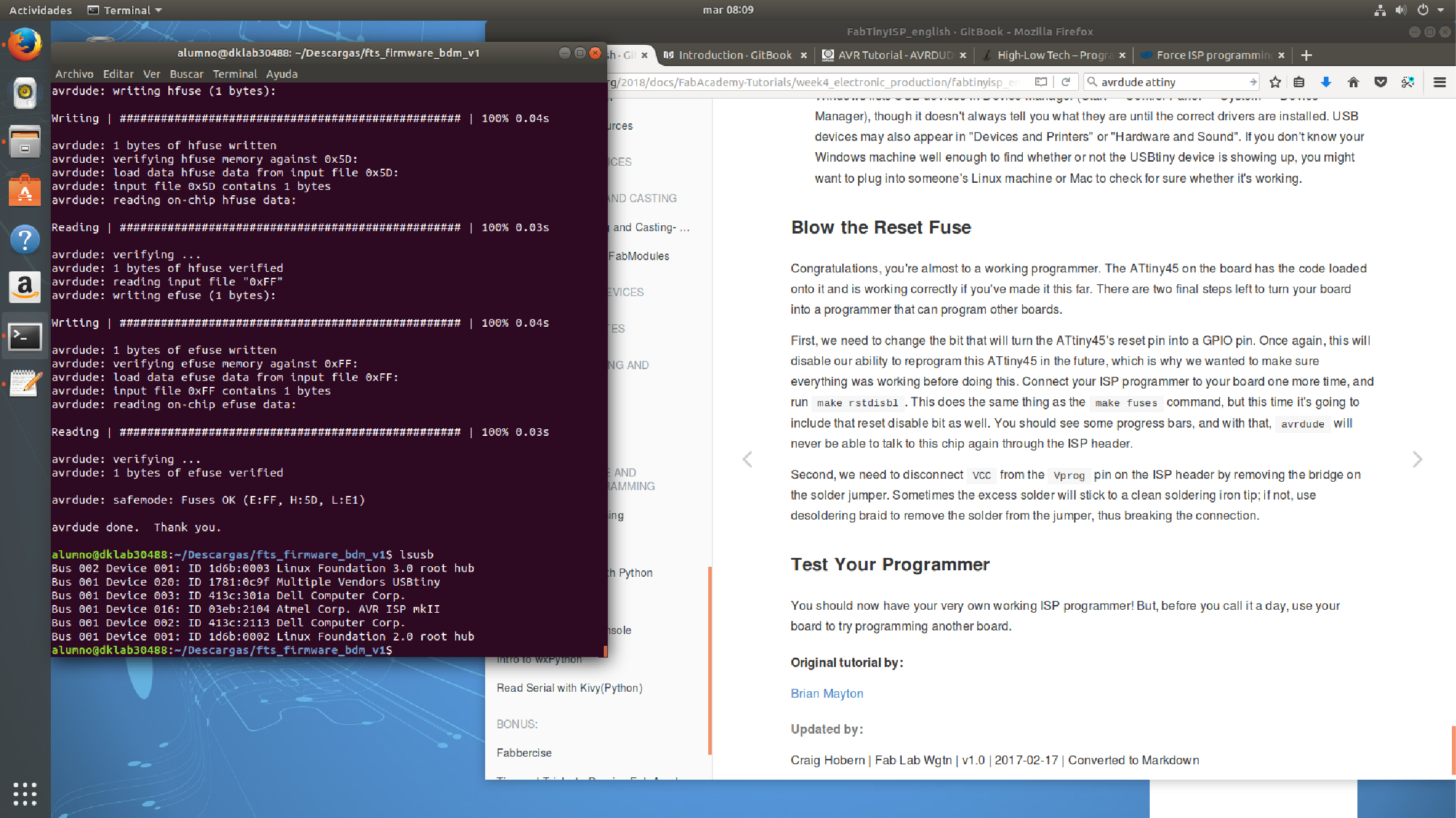
Thanks to this change I was able to set the configuration fuses and
Fts_mini_traces:Download PNG file. Fts_mini_cut:Download PNG file.