W14│ Networking & Communications
Individual Assignment:
- Design and build a wired &/or wireless network connecting at least two processors.
1. Individual Assigment.
1.1 DESIGN AND BULS A WIRED &/OR WIRELESS NETWORK CONNECTING AT LEAST TWO PROCESSORS.
As it is getting close to the final presentations I've been using the assigments for my Final Project. The product I'm designing has two main objects, a Mat and 2 Dumbbells, I've already tested how the Mat> is going to work and this assigment was perfect to connect the Dumbbells with the mat. I decided for my Final presentation to show to type of exercices: Run in Place & Squats. For the Dumbbells I'll use a Sonar Sensor .

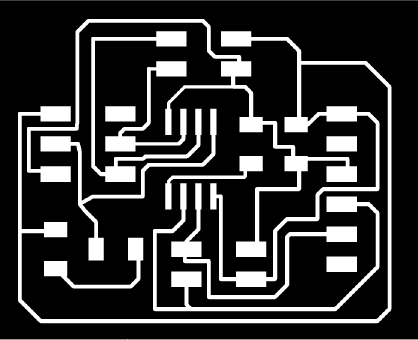
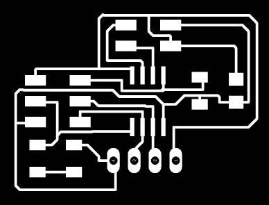
a. Schematics & Board
I'm using RS232, it was necesary to have two different boards, one is the Brigde and the other the Node. For the first one I redesing Neil's and I added the components from the Touchpad I made and for the second one I mixed up Neil's with the Sonar board suggested in Input devices.
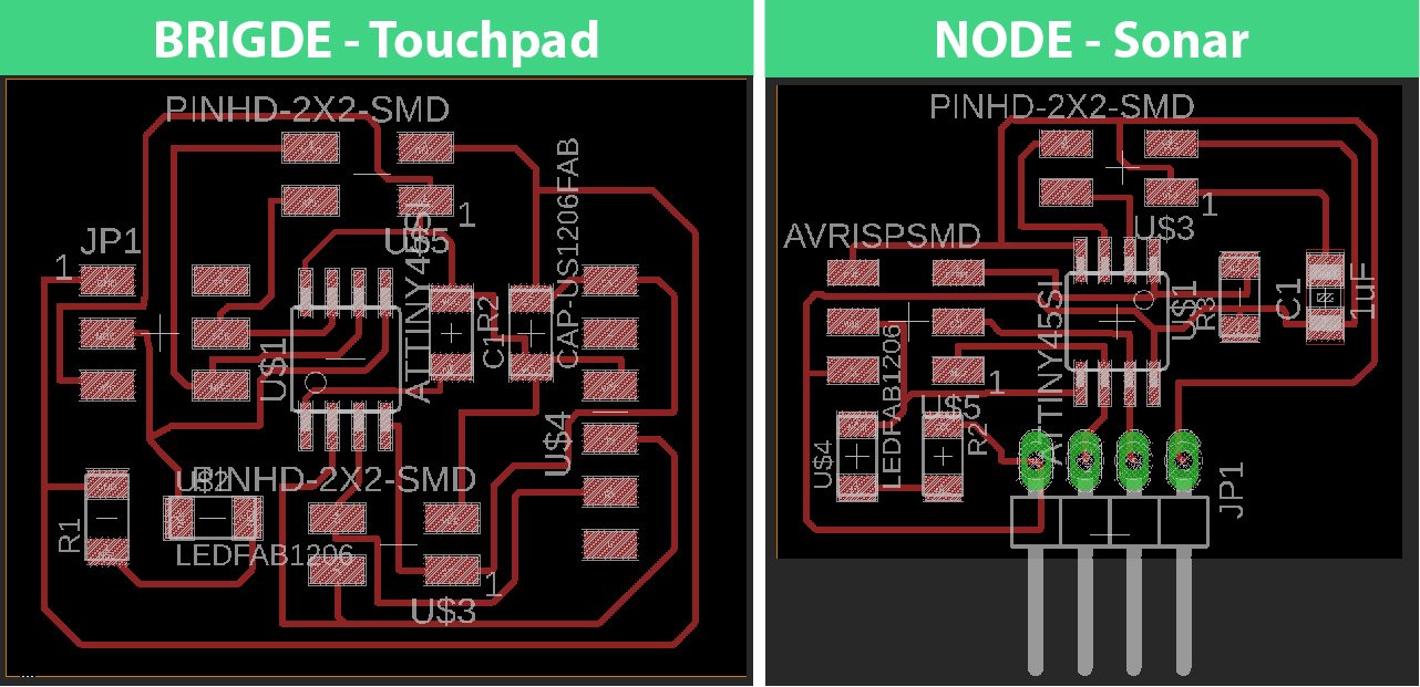
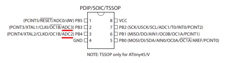
I´m still using Attiny 45. With the Sonar board I didn´t have any type of trouble, I just needed to be really careful with the PINS I used for the NODE, the Datasheet help me to find wich PINS had analog to digital Converter (PB3 & PB4).
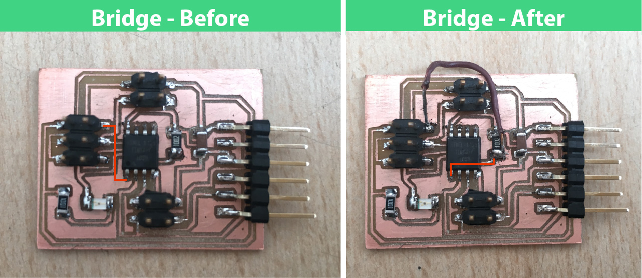
With the bridge board I had some troubles but I noticed them when I wanted to program it. My mistake was: I' didn't connect one pin of the PINHD-2x3-SMD to the Attiny45. In order to fix it I used a wire to connect them. After that it worked.
b. Programming - Touchpad.
In order to test the board I used Neil´s code (hello.bus.45.bridge) and everything worked perfectly.
After that I needed to mix my code from the output's assignment and Neil's brigde code. I could turn on the LED but I couldn't turn it dowm. What I found out: millis() function was interfering with PUT_CHAR (function used to send characters), it was interrupting PUT_CHAR too often.
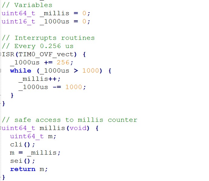
Without millis() the Attiny45 could receive characters but couldn't send any characters. To solve this I needed to configure the serial_pin_out correctly.
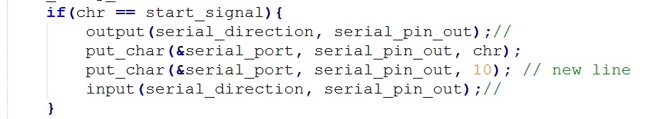
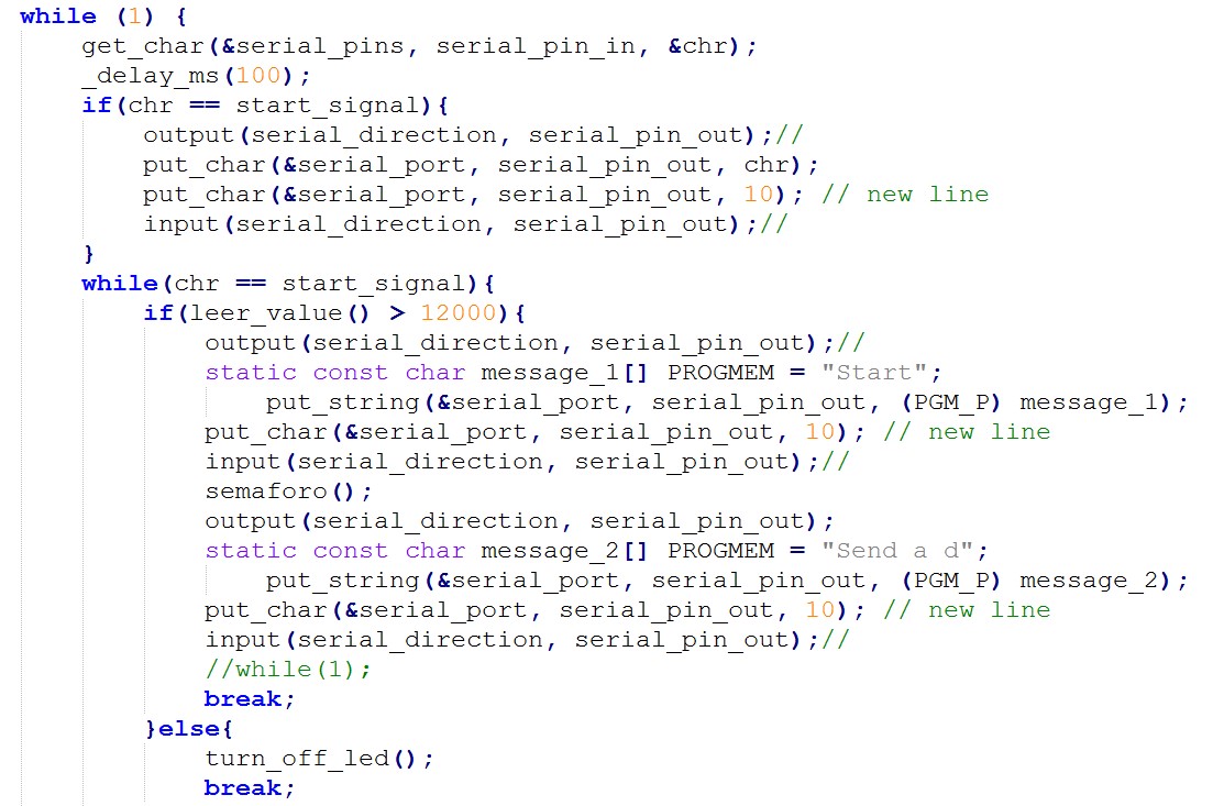
At this point I reconsidered how I wanted my Pad to fucntion. For this assignment I just needed to send a start message ("s") in order to sense whether the Pad was touched. After that a RED LED sign (3 blinks)was shown and a message ("d") was sent to the node to start usign the Dumbbell.
b.Dumbbell - Programming .
Before mixing up codes I tested the board with the Sonar's code from (hello.HC-SR04.c) It worked pretty good.
I made a new function called meassure_distance() and added a filter based on Neil's. It allowed me to count how many times the sonar sense a distance less than 20 cm, this was written as squat() function.
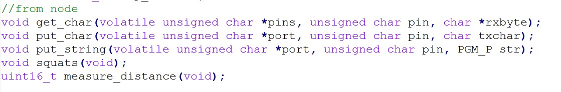
In order to make this board to function as NODE it needed to receive characters while connected to the brigde's network. I added three functions from original node's code: GET_CHAR, PUT_CHAR and PUT_STRING
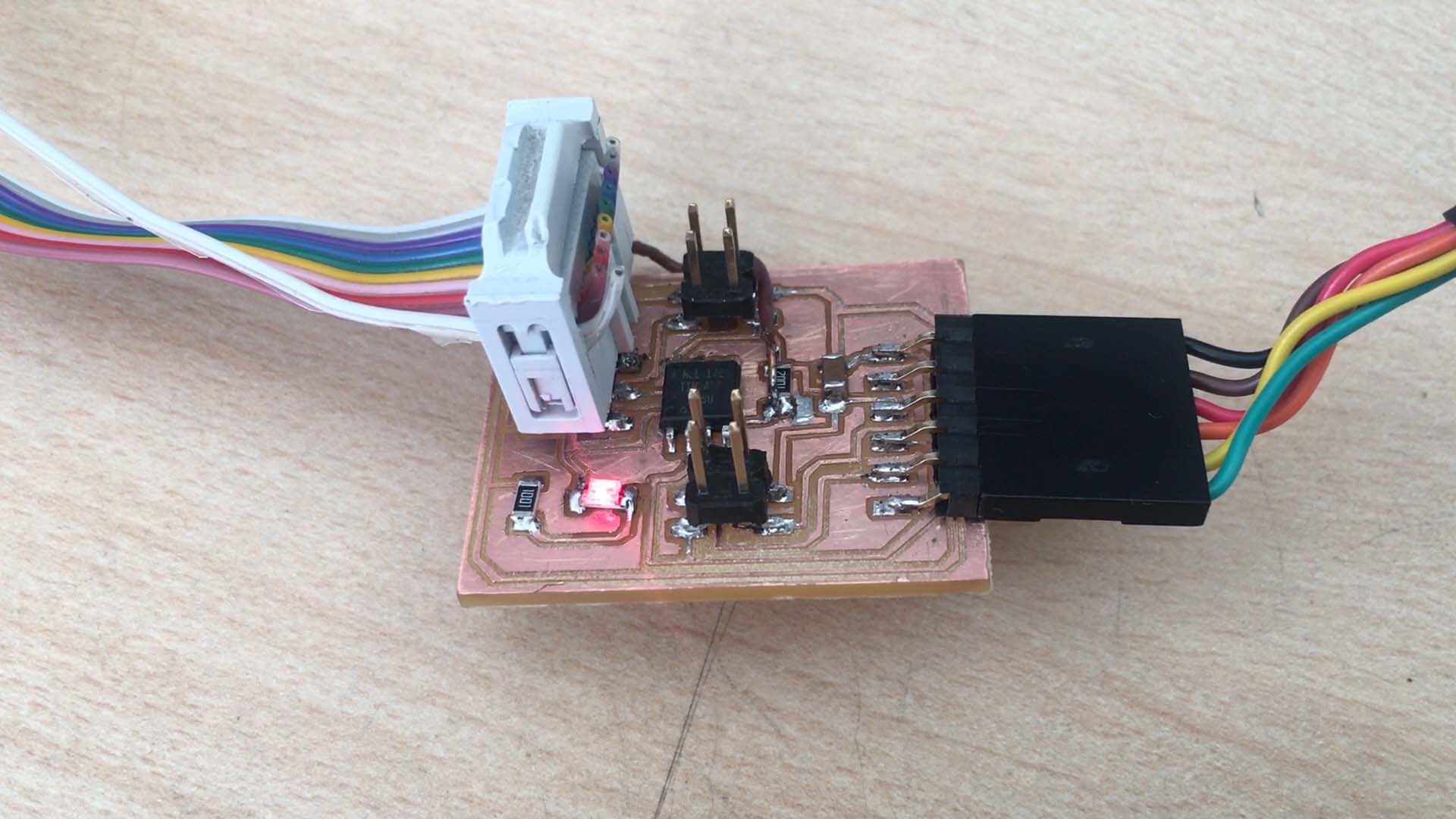
RESULT
1. Ass an APP I used BlueTerm2 to manually send a "s" (Start signal) to the PAD.
2.If the user is touching the PAD, a RED LED sign is shown and the PAD sends to the app "Send a d".
3.As soon as I read the message I manually send a "d" to the dumbbell.
4. The DUMBBELL receives the "d" and starts counting squats. After five squats it sends "Good Job!".
Interface and Applications Programming from alucyem on Vimeo.
FILES
PAD: Schematics / Traces / Interior / Code
Dumbbell: Schematics / Traces / Interior / Code