W12│ Output devices
- Add an output device to a microcontroller board you've designed, and program it to do something.
1. Individual Assigment.
2.1 ADD AN OUTPUT DEVICE TO A MICROCONTROLLER BOARD I´D DESIGNED AND PROGRAM IT TO DO SOMETHING.
For this assigment I continued exploring options for my
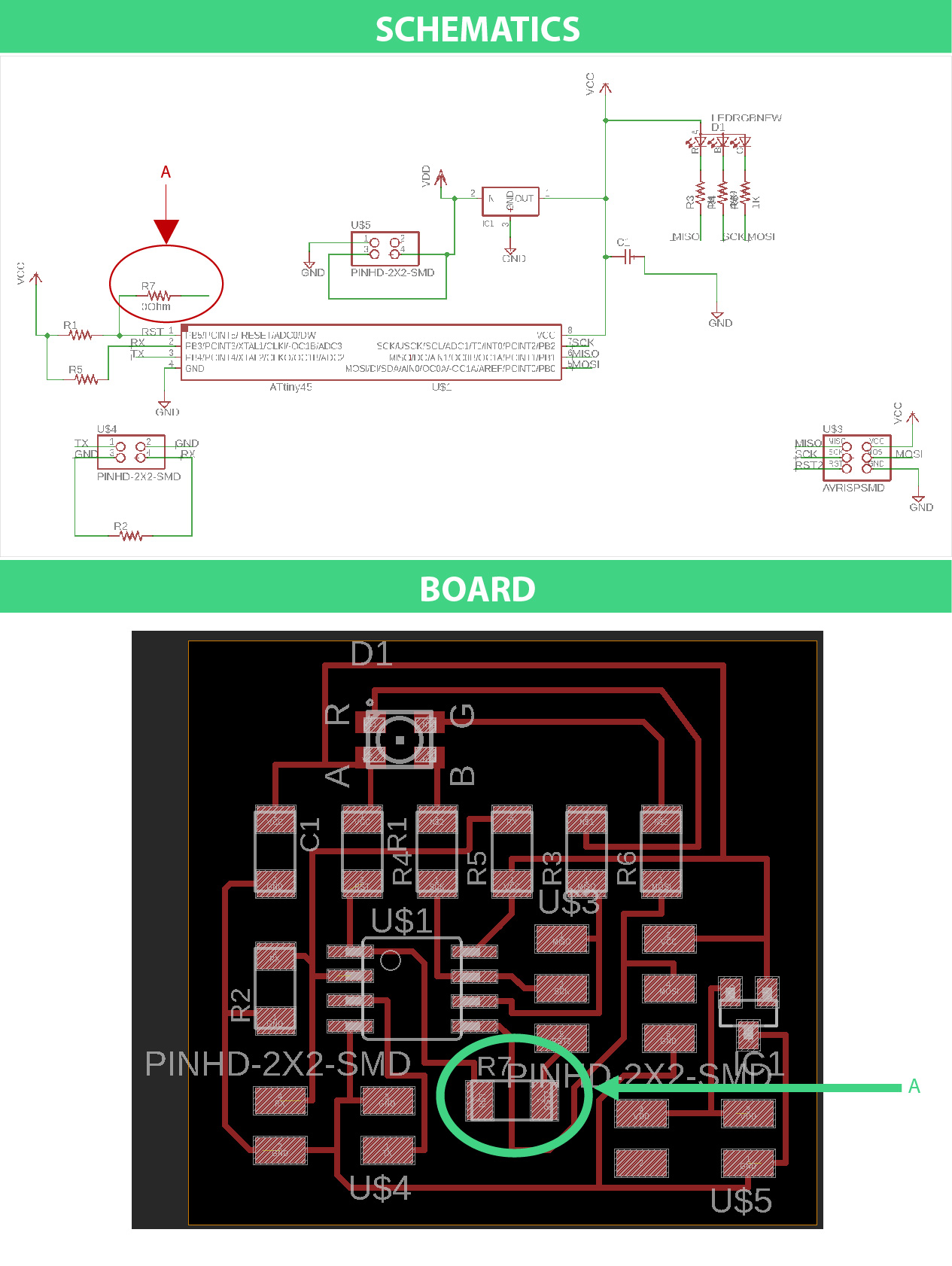
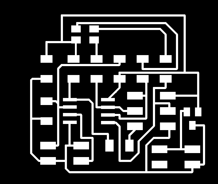
So, in order to conect what I've already made on last week's assigment (Input devices) I modified Neil's board from
The main trouble I faced was conecting the route between the components and I spent a lot of time making different routes without achiving any result just a headache, until Daniel (he's part of Tecsup's Fab Lab staff) suggested me to add an 0Ω resitor, with it I connected components without affecting anything.
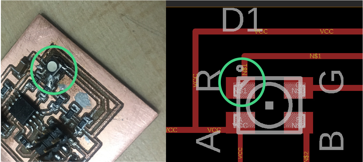
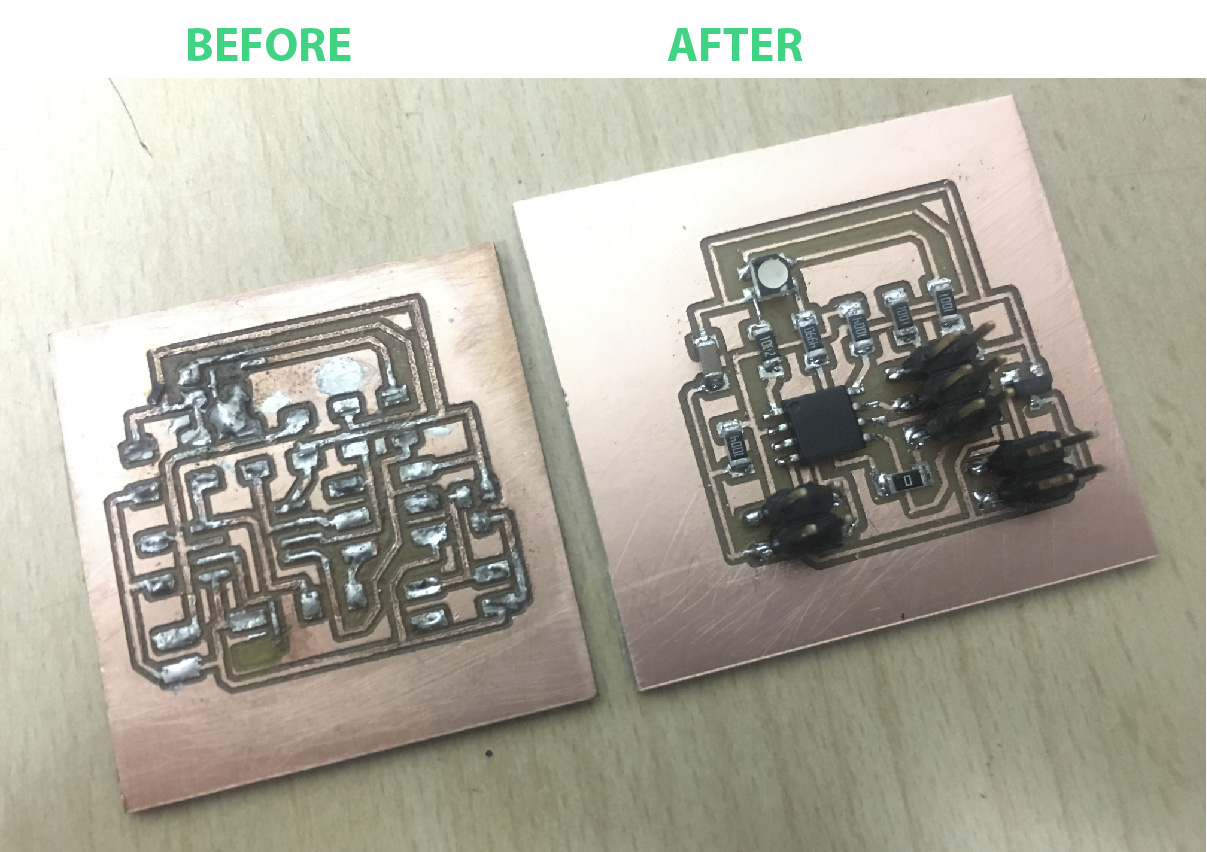
The milling traces had rough edges and the general aspect wasn't what I expected but I went ahead with the soldering part and I made as mess. My biggest mistake was that I soldered the RGD LED in a wrong position connecting the Red pin (PIN 1-package marking) with the Green pin's route. I used the heat gun to remove the RGB Led and due the overheat the copper trace broke and my "great" idea was to add more tin and make a mountain of it. As you can see everything looks awful and My OCD spirit was about crash. So I ended up by doing a new board and soldered everything in the right way again.
I wantend to verify if everything was working OK so I used Neil´s original CODE.
The main idea of my
In order to do that, i used the function called Millis to count one second. The program shows an start sign. If the pad detects 2 touches the RGB led will turn magenta, and if it detects only 1, the touch will turn cyan. After that second the program resets and display the start sign. I based my code in the following example:
LINK TO THE EXAMPLE ON GITHUBHow does millis() work? It uses an internal interruption callled TIMER0_OVF that happens every 0.256 us to add 256 to a counter called _1000us. When _1000us is greater than 1000 it resets and increments another variable called _millis. The function millis(). recovers that value, and is an aproximate value of the transcurred time from the beginning of my program
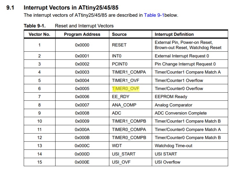 I used the microcontroller's datasheet to find an internal interruption to use in my code. I'm working with the TIMER0_OFV
RESULT
Output devices from alucyem on Vimeo.