W11│ Input devices
- Measure the analog levels and digital signals in an input device.
- Measure something: add a sensor to a microcontroller board that you have designed and read it.
1.Group Assignment
2. Individual Assigment.
2.1 MEASURE SOMETHING: ADD A SENSOR TO A MICROCONTROLER BOARD THAT YOU HAVE DESIGN AND READ IT.
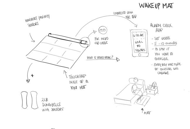
Electronics and programing are new subjects to me and I really enjoy this assigment, because I was able to test and alternative that I can use on my
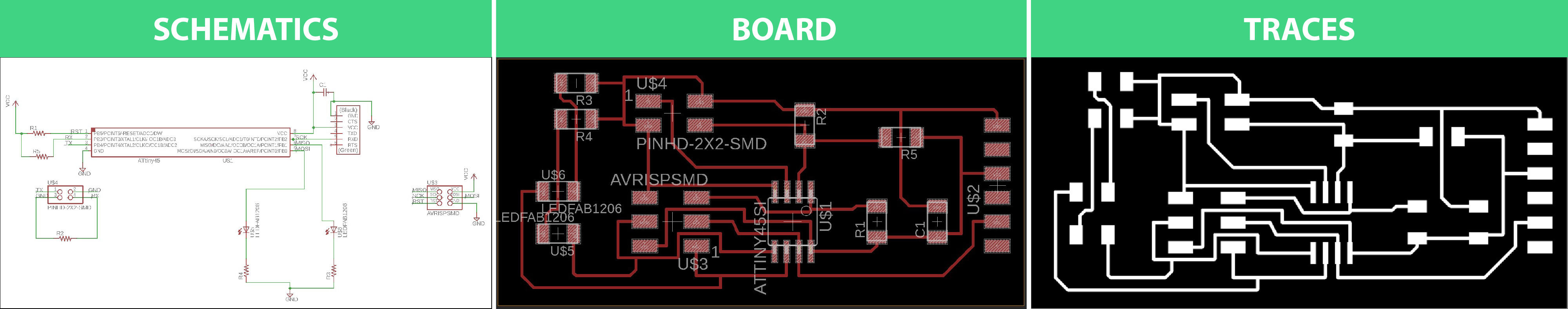
I used Neil's demo
I decided to continue to use the ATtyni45 (as Neil´s demo) because, for this project, it was only required to add
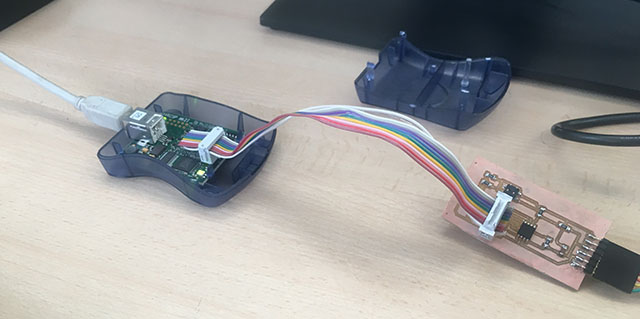
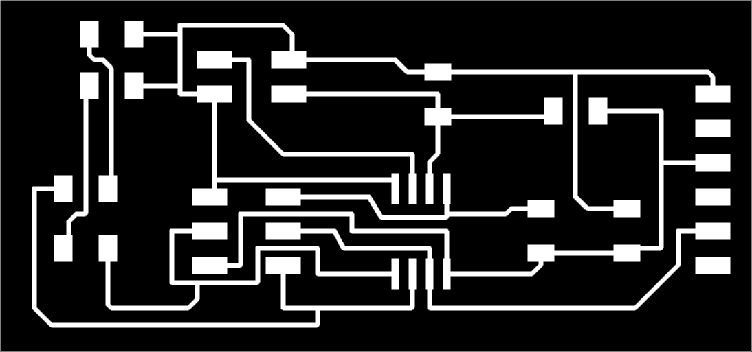
This part is really mechanical and easy but in this opportunitty afte milling my board the traces where really thing and I was worried they won't work. After soldering I use a multimeter to test continuity. Fortunately, there was not any issue on the board and I was ready to test my idea.
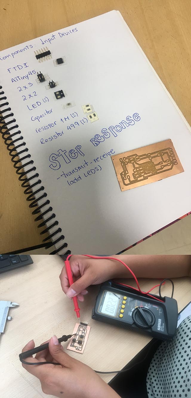
It was time to face the unknown: How to use the copper pads. To achive it I need to solder 2 cables (one for each pad) and use a 2x6 pin header to connect them to the circuit board.
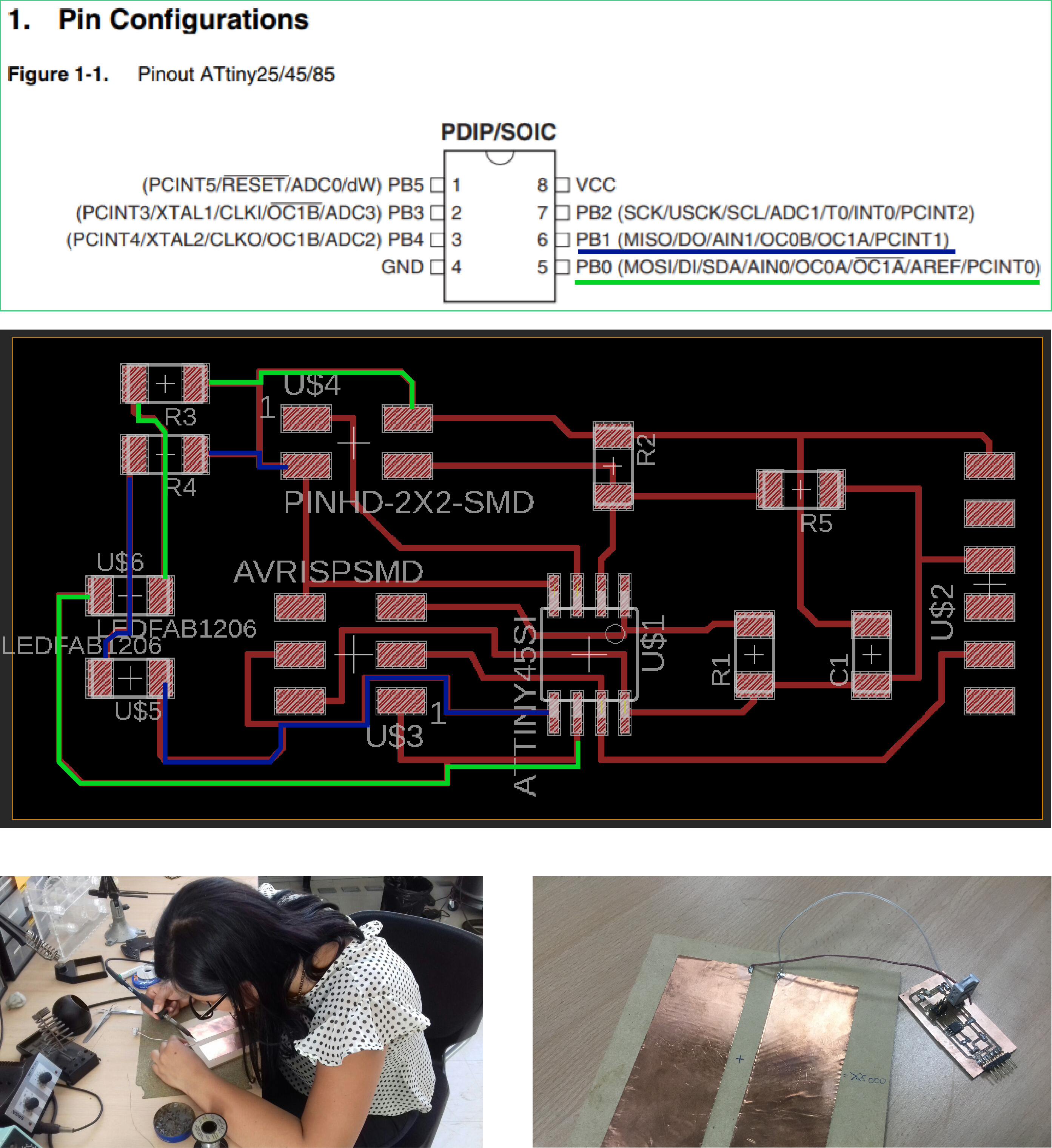
- Before I soldered the cables, I looked up the ATtiny45 Pin configuration (
from the Data Sheet ) to locate wich PINs where conected to the LEDS. Later, on the programmation part we will use these information again.
I used Neil'code first to test the funtion of the copper pads without the LEDS: Here the steps I followed:
1. I downloaded the Makefile and used the AVR programer(avrisp2)on Ubuntu's terminal to program the
2. Then I run Neil's code (C language)
3. Everything was working ok until this point. To receive and display transmit-receive step response I needed to run the Python file
After checking that everything was working OK with the copper pads I needed to modify Neil's code in order to program the LEDS. Here the steps I Followed:
1.Neil´s code was written in C language, I don´t have experience with it so I needed information on how to program LEDs with C language. I found that in a tutorial that the code used to Blink a LED was:

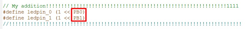
2. Neil has define as: 
3.Now I had to define the LEDpin I will use frm the Attyni45 PIN configuration.
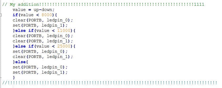
4.I needed to specified wich copper pad will light on each LED. To do it, first I tested the right copper pad with the display "transmit-receive" and I got values under 8 000. The left copper pad showed values over 11 000 and when I touched both copper pads at the same time the values went over 25 000. Here how I use the Values:
RESULT
Input_devices from alucyem on Vimeo.