Attending the Fab Academy in Barcelona, I document each week of intense learning as I come across new digital fabrication techniques.
This documentation is as much a report of what I do as a reflection on why I do so, and will hopefully guide me back to Oceania to spread and make good use of the knowledge gathered along the path.
--- summary of the assignment ---
objective :
Design a 3D mould, machine it, and cast parts from it.
what I did :
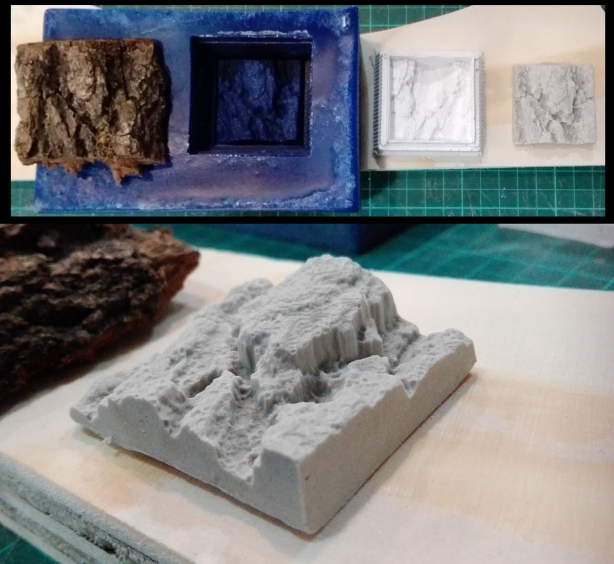
I scanned, made a mold then cast a replica of a piece of bark.
download :
Learning outcomes :
22.03.18 /The molding and casting week has begun. As a first test I am planning on 3d scanning something and making a one-sided mold. I go throught the documentation of the 3d scanner we have here :
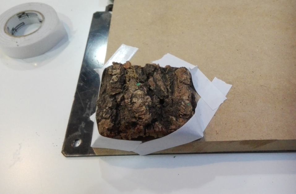
I use the MDX-20 since it can only 3d scan by projection, which is what I am after in order to make a one-sided mold. I look around for a shape that offers an interesting texture from one side which I would have great trouble designing on a computer. An organic shape would be ideal. I look around in the lab and find my model, hidden in a junk section :
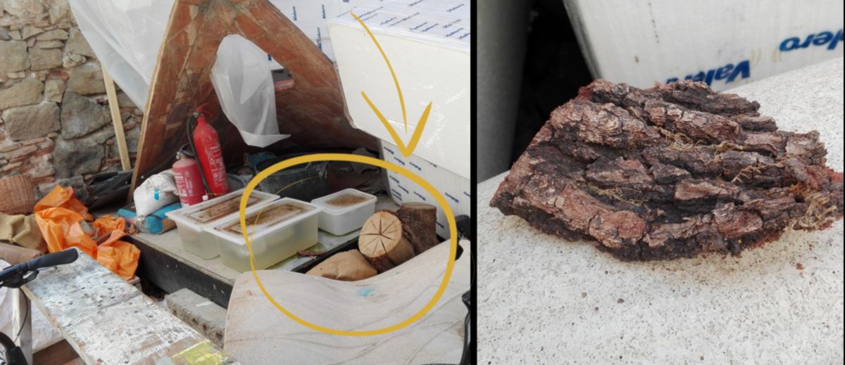
I set up my sample on the work plate and stick it into position the best I can. the bottom of the sample is very porous therefore neither clay, playdoh or double-sided tape offer enough adherence to hold it ino place. I have to wrap the corners into some tape :
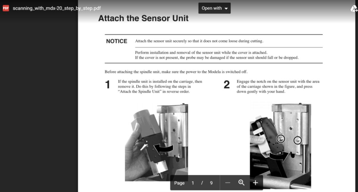
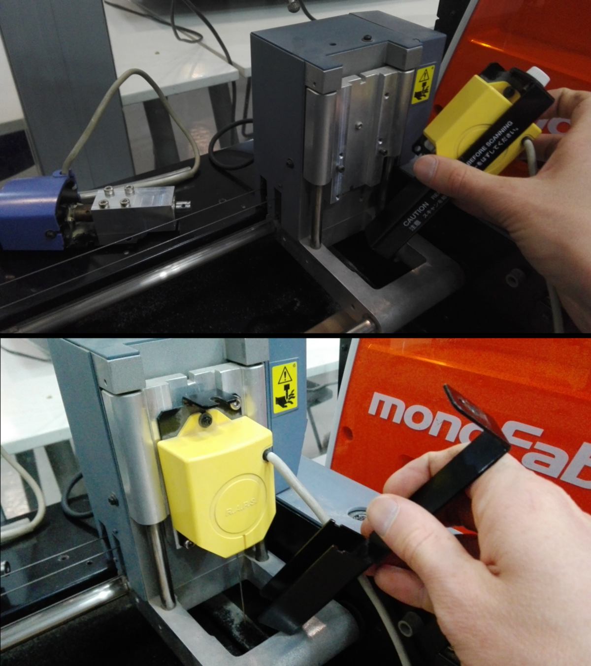
I install the sens0r unit onto the mdx20, and remove the protection of the probe carefully :
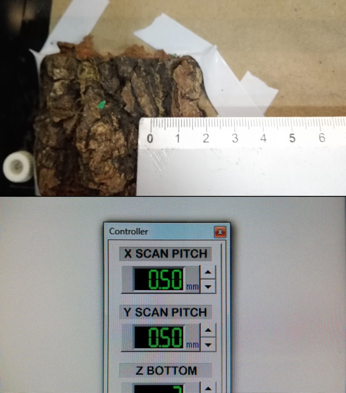
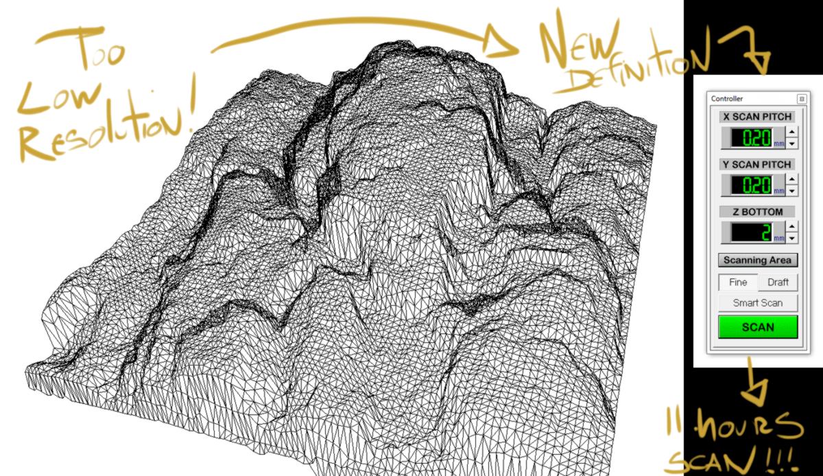
I set up the definition of the scan. The material is small and so is the texture, so I increase the definition fro 1mm to 0.5mm :
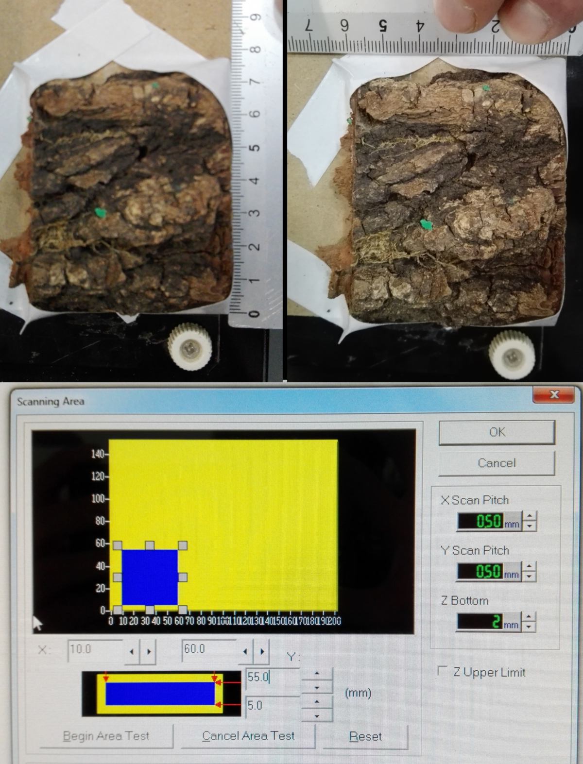
I set up the surface to be scanned manually, entering dimensions and double-checking it. The scanning process is slow, therefore I want to make the scanned area as small as possible, getting rid of the taped areas :
I finally begin the scan. The probe scans the object in a way I was not expecting. I thought it would go in (x=0,y=0), go down until it senses resistance, record this location, then go back all the way up, move in y and x, and do it all over again. This would be of course a very slow process, so the scanning process has a more intelligent approach in order to reduce scanning time. It make use of the fact that the probe can sense resistance not only on the z axis, but also in y (from the side).
I look for a detailed explanation on the web but cannot find anything relevant, so I have a closer look at the way it moves :
During step B, the probe begins its journey from the point on the left-hand side, then moves up and right by the spacing I selected earlier (0.5mm) until it senses resistance. This approach makes sense to me. Step A, however, does not. if the probe can sense resistance from the side, what is step A required for? Why not beginning at step B?
Looking at the probe, its diameter varies, narrowing at the tip. Perhaps taking a measurement using a high position on the probe would return the wrong dimension. Perhaps only the end of the tip is able to sense resistance. The scan slowly goes on, and will take around 3 hours to end.
I find some more information from James Fletcher, a former Fab Academy student :
"The simplistic way to scan would be to step across the scan area in pitch step increments completely raising the scanning tip each time and then dropping it back down again. Based on our quick time to scan estimate earlier on vs. the actual time it took to do a scan and on observations of the machine scanning the process appears to be much more intelligent than that.
The first thing to note is that t needle doesn't operated a simple switch when it drops down and touches the object. It is actually a piezoelectric sensor. This means that it will resond to deflections in the x and y directions as well as the z. With this the machine appears to sweep the tip across the object at a constant low height until it touches an edge. When it touches it lifts up until it clears and then continues it's sweep. with this information it can work out a better approximation of the boundary of the object than that provided by our simple scan area estimates and z upper limit. With this better boundary information it returns and performs a high resolution scan of the object only just lifting the scanning tip just enough to clear the object and saving a lot of time moving the head on the z axis. "
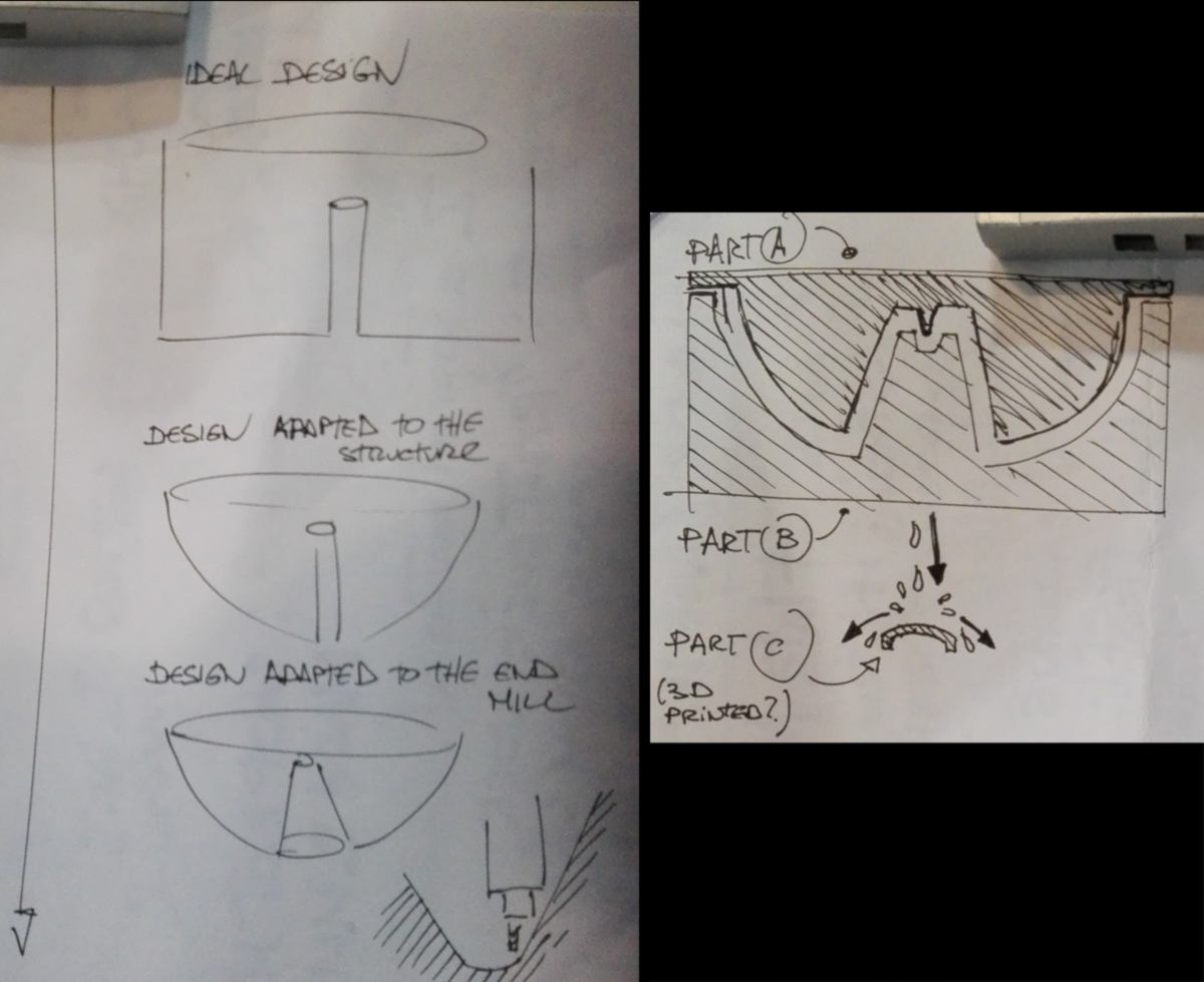
Back to the green wall, I intend to mold the bowl. It is quite large (600mm diameter). I chatted with Guillaume (from the Aquapioneers) about my design. He mentions that from a production perspective, rafts are much more efficient, easier to place and harvest, and fit most leafy greens. He would recommend media bed for fruit trees only (tomato plants etc.). This makes me think that my design is a good learning experience from a design perspective, but a more square, simple design might be better suited for food production.
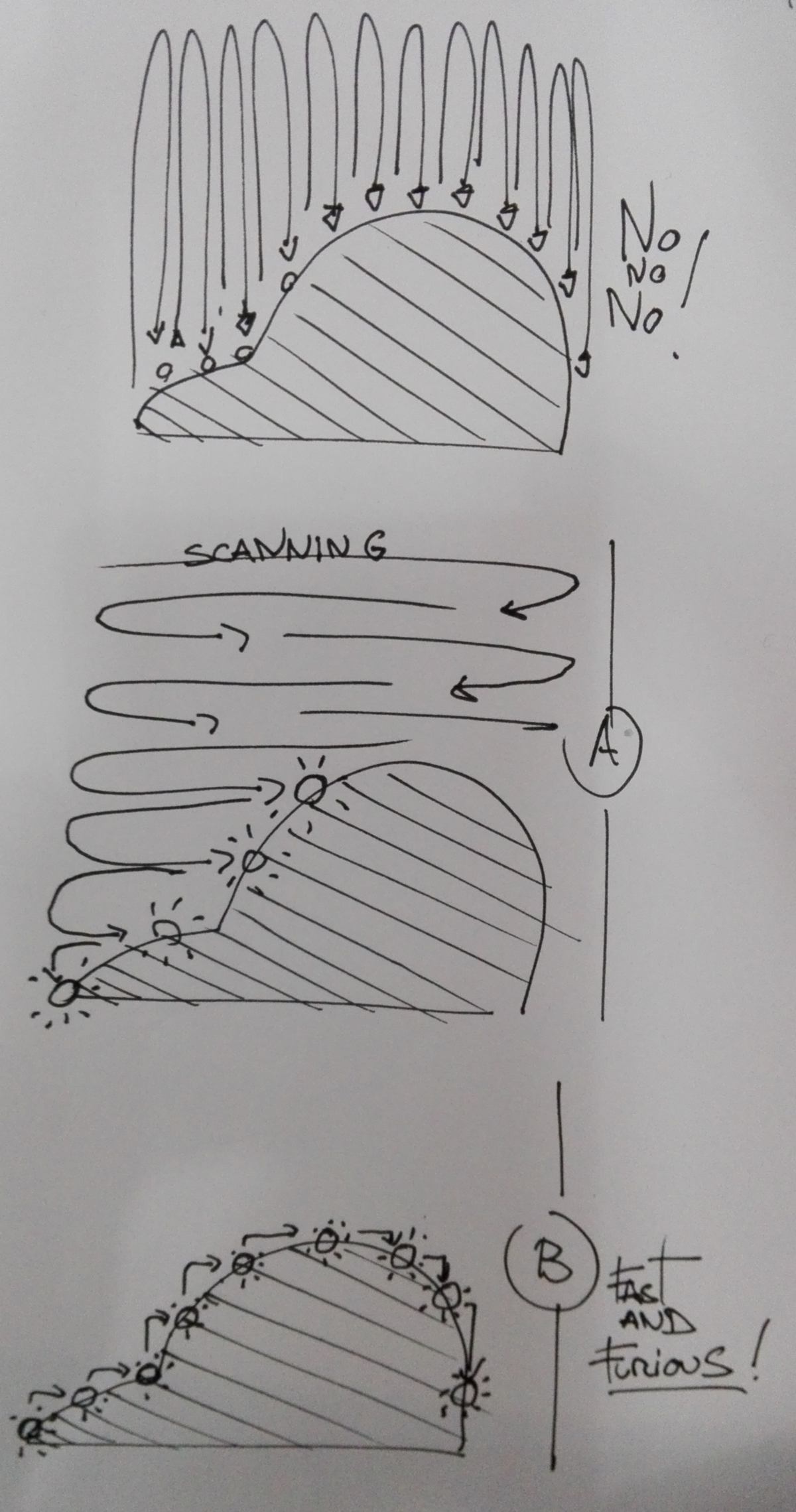
I will however keep going with my design for the next two weeks. I plan on re-designing the bowl if possible, adapting them to the raft system. This will also make it easier to mold, getting rid of the complexity of the siphon system. I begin to think about the design of these bowls. I have to find the best compromise between space available for the roots and the angles required for the end mill to go many centimeters down while cutting the mold :
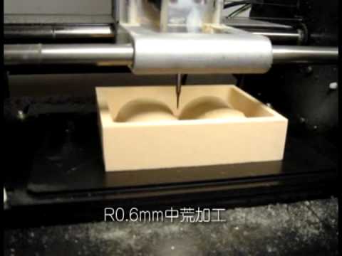
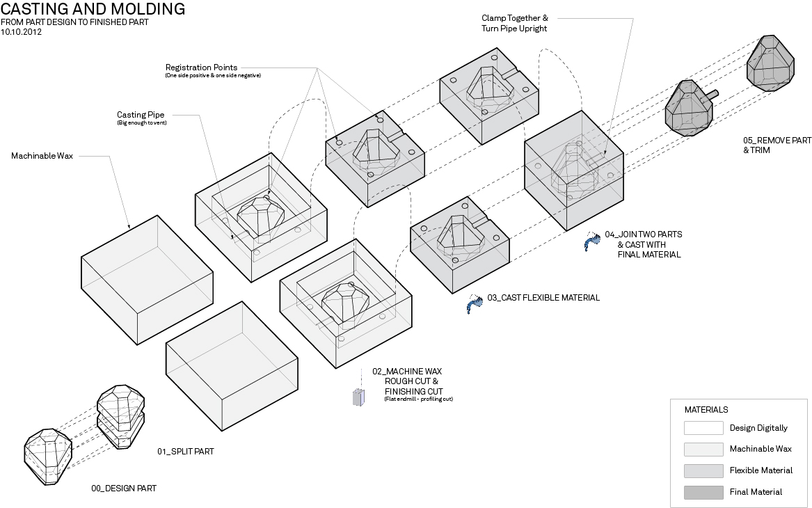
this afternoon, we cover the basic of milling the mold, and a molding workshop. We see step 1 of the workflow required to have a final piece :
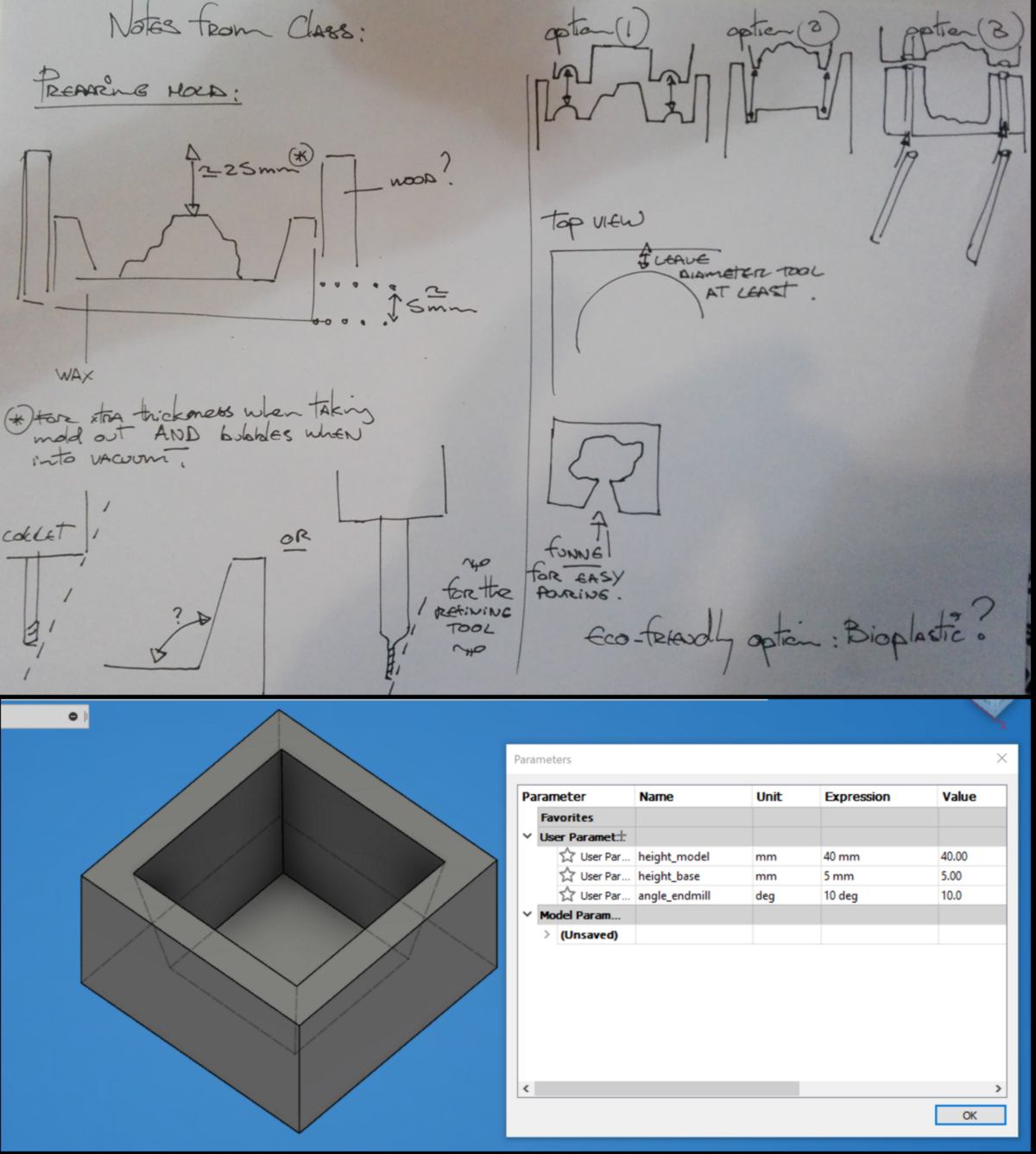
I am preparing the container for the scan of the bark. I create a few parameters to ensure I respect the few design rules discussed during the class :
I also have a look at the render of the scan of the bark. With a definition of 0.5, the texture is not recognisable as bark. Therefore I begin another scan and will leave it run overnight.
With such definition I am likely to use a 1/32 tool to mill the finishing strategy. The collet will not get in the way since my design is very flat, however this tool narrows down at the tip. I therefore have to take it into account while preparing my 3d scan :
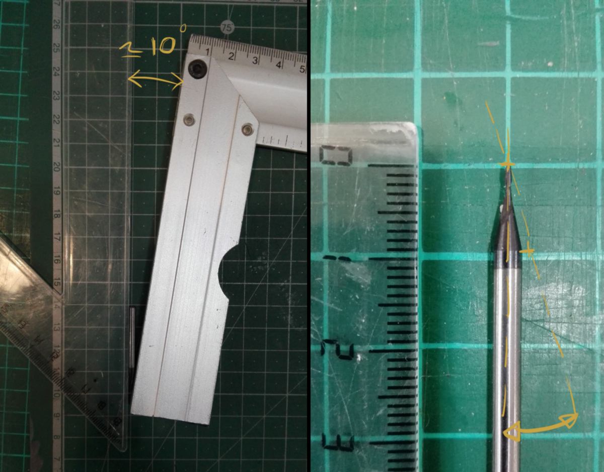
Any angle can't be sharper than 10 degree past 1omm. Otherwise the mold will be damaged.
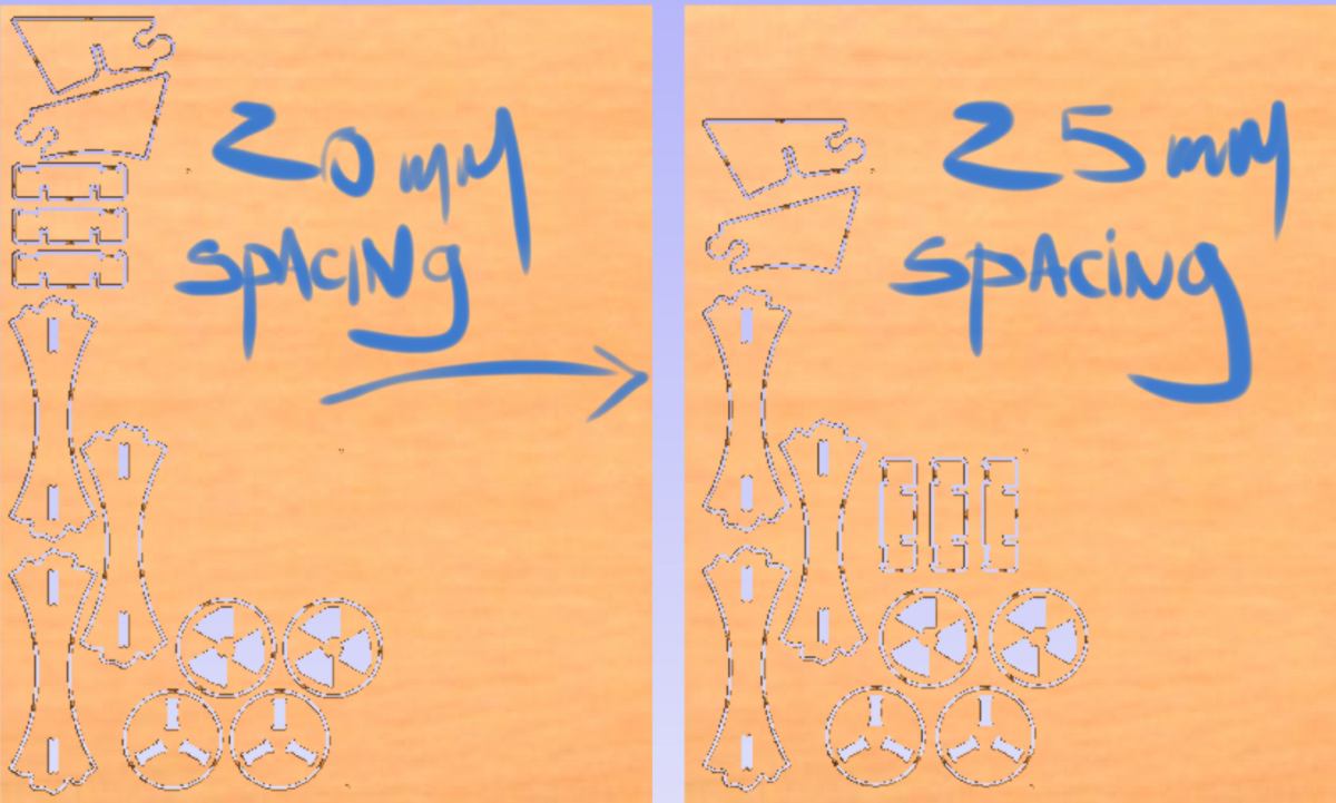
I switch to the nesting of my piece. I have been recommended to leave at least 25mm between pieces, so I adjust my nesting. The CNC is booked for tomorrow all day.
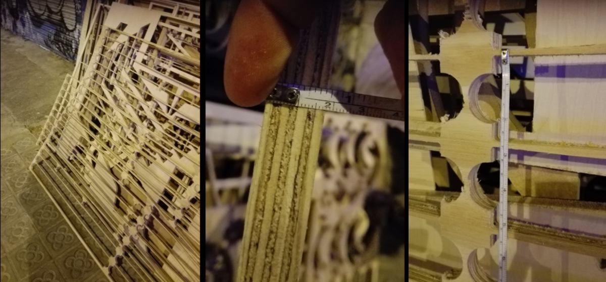
While walking back home, I notice some cut sheets of plywood. They really maximise the use of the material, leaving close to nothing between cuts. the cut surfaces look really rough. I wonder if it has to do with the vibration generated by the loose attachment of the material to the workplate.
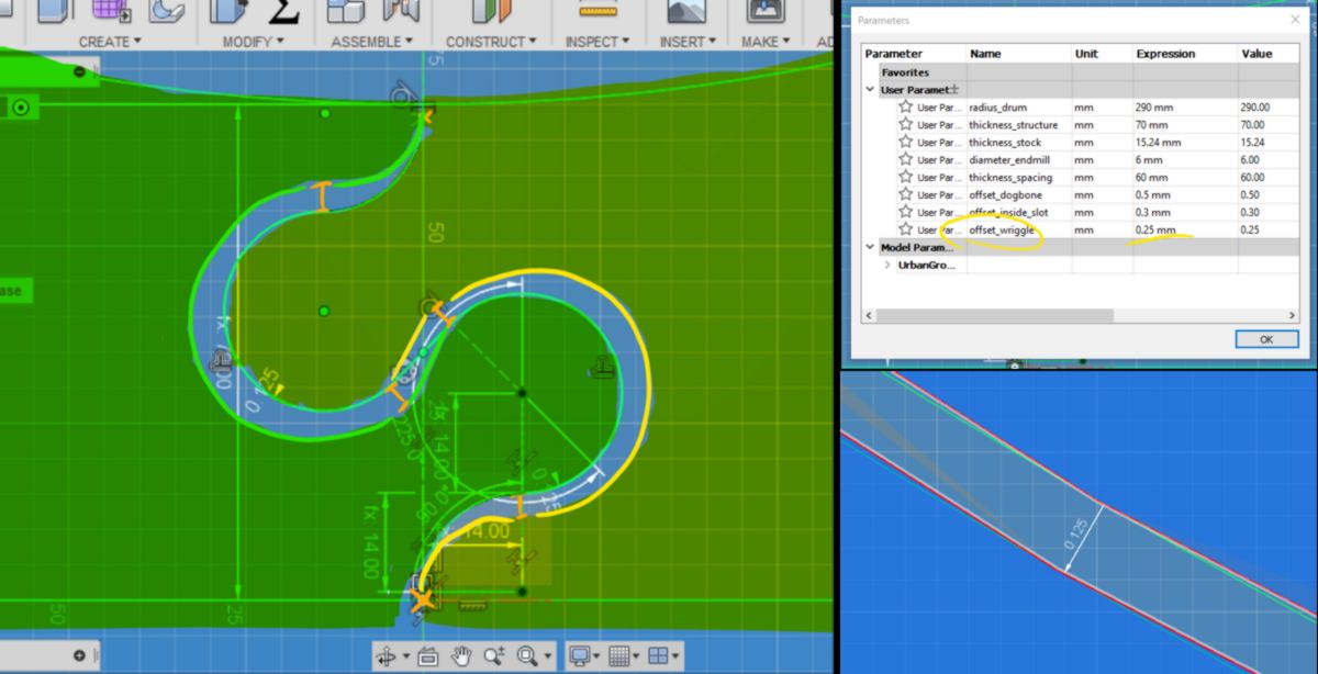
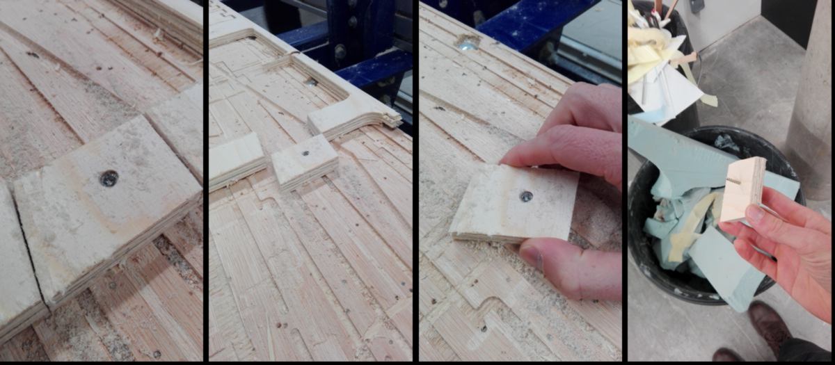
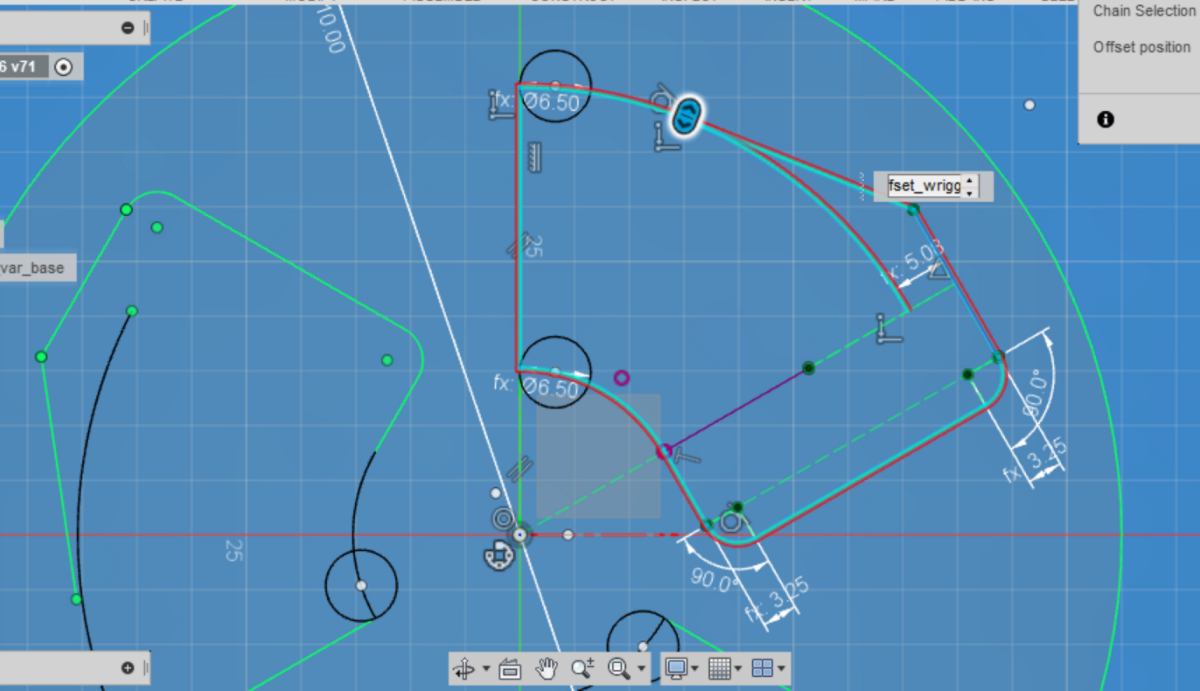
23.03.18 /Last finishing touch before cutting. All inner slots have previously been widened by 0.3mm. I now adjust the tolerance for the "wriggle joint", adding a little bit of wriggle room, but making it a little tighter than other joins :
I will spend my whole day going from the molding and casting assignment to the CNC machine and back. For documentation purpose, I will talk about one subject, then the other.
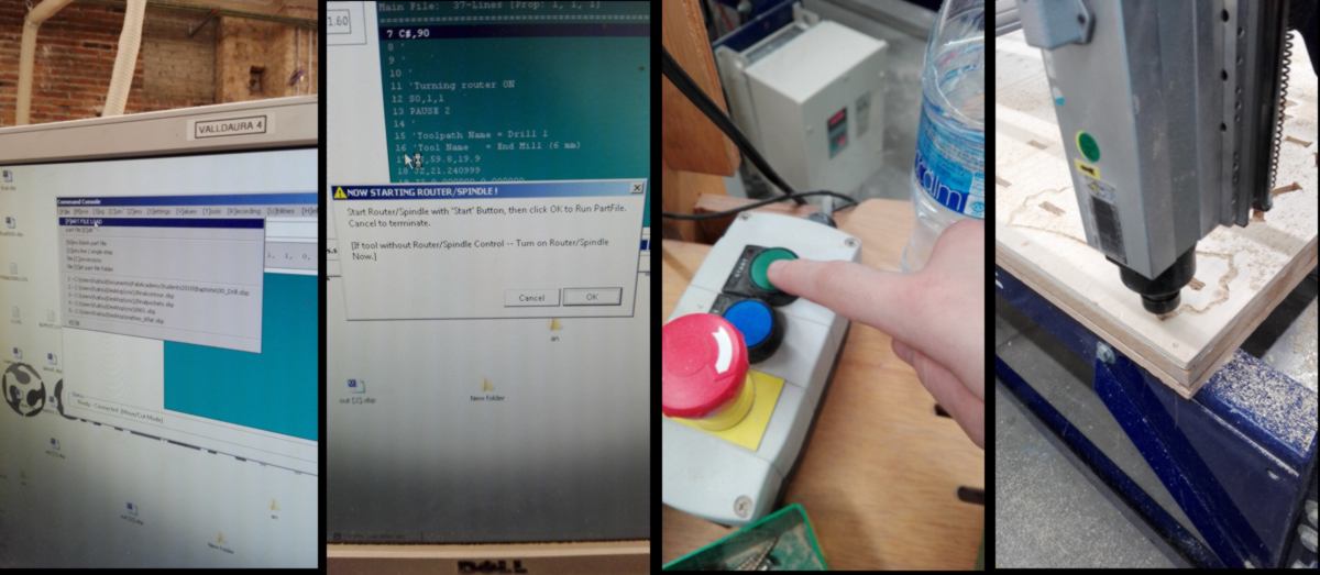
Let's begin by the CNC cutting. Before heading to the machine, I get my strategies checked by Santi. We correct the step-over of the tool, modifying it from 40% to 70%. Therefore the cut will take less time. We also add a screw and adjust the positioning and size of the tabs, making them smaller.
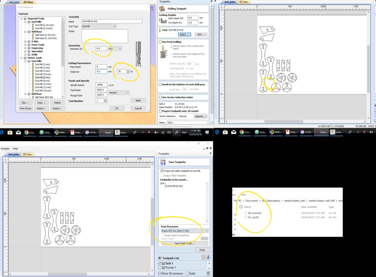
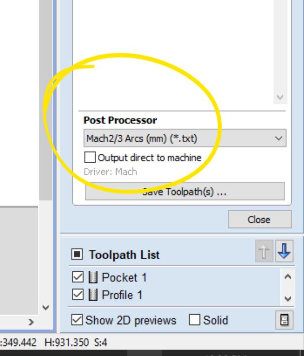
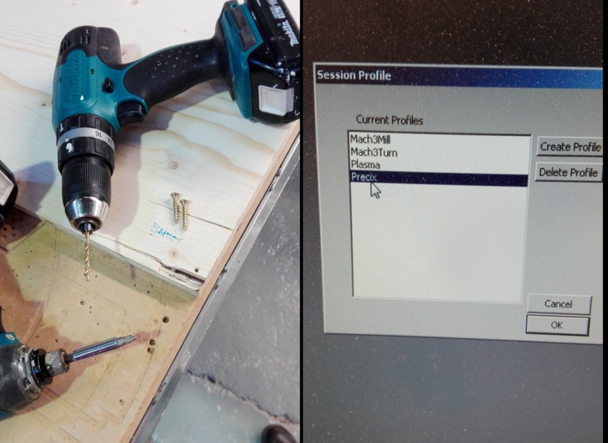
We export two g-codes (one for the drilling of the screw, the other for the cut itself) using a process that generate a .GC (which I guess stands for G-Code). Mach 3 does not recognise it immediately, but when pointed at it, it is able to translate it into a g-code. I will nevertheless re-export it using a processor that I am familiar with and that is immediately recognised by Mach 3:
Time to head to the CNC. This is a Precix that has been very recently repaired. The sacrificial layer is in poor condition, so I ask around how to skim it. I am being shown the largest end mill we have. However these tools are imported from the USA, and are in inches, whereas the collet of the machine is European, and is in mm. Often tools a little larger can be pushed into the collet, but this time the diameters are too far apart. We look around for large end mill in European standard, but cannot find anything. We decide to postpone the flattening to next week.
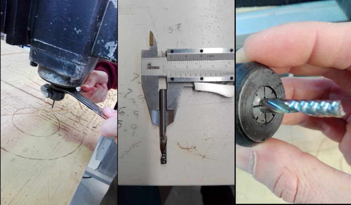
I set up a 6mm one flute end mill. But before that I have to extract another end mill stuck into the collet. This is a US end mill on a European collet, and it takes a bit of a fight to get it out. I set up the new end mill and ensure the maximum amount of it is inside the collet, without covering the top part of the flute:
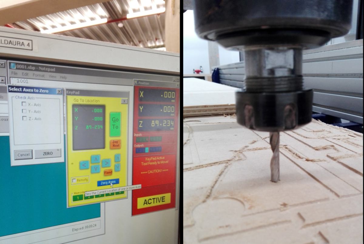
Mach 3 and I get to know each other a bit. I have used this software before, so I quickly set up the zero in X and Y, aligning it with the sides of the table. For the Z-axis, I learned how to use an end plate. This end plate is used as a receiver for the end mill. The end mill slowly goes down until it get in contact with it, and zero itself on the Z-axis. A much more accurate process than my precedent one : agitating a piece of paper between the end mill and the sacrificial layer until it stops moving.
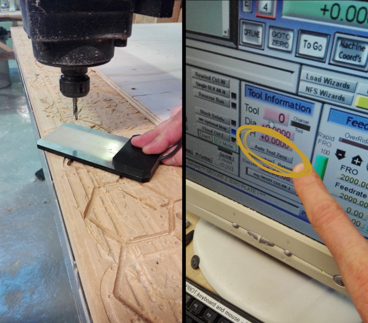
The end plate does shake a bit when the end mill gets in contact with it due to the irregularities of the sacrificial layer, and the cable connecting it to the CNC is surprisingly too short, so I re-do this maipulation many times before getting it right.
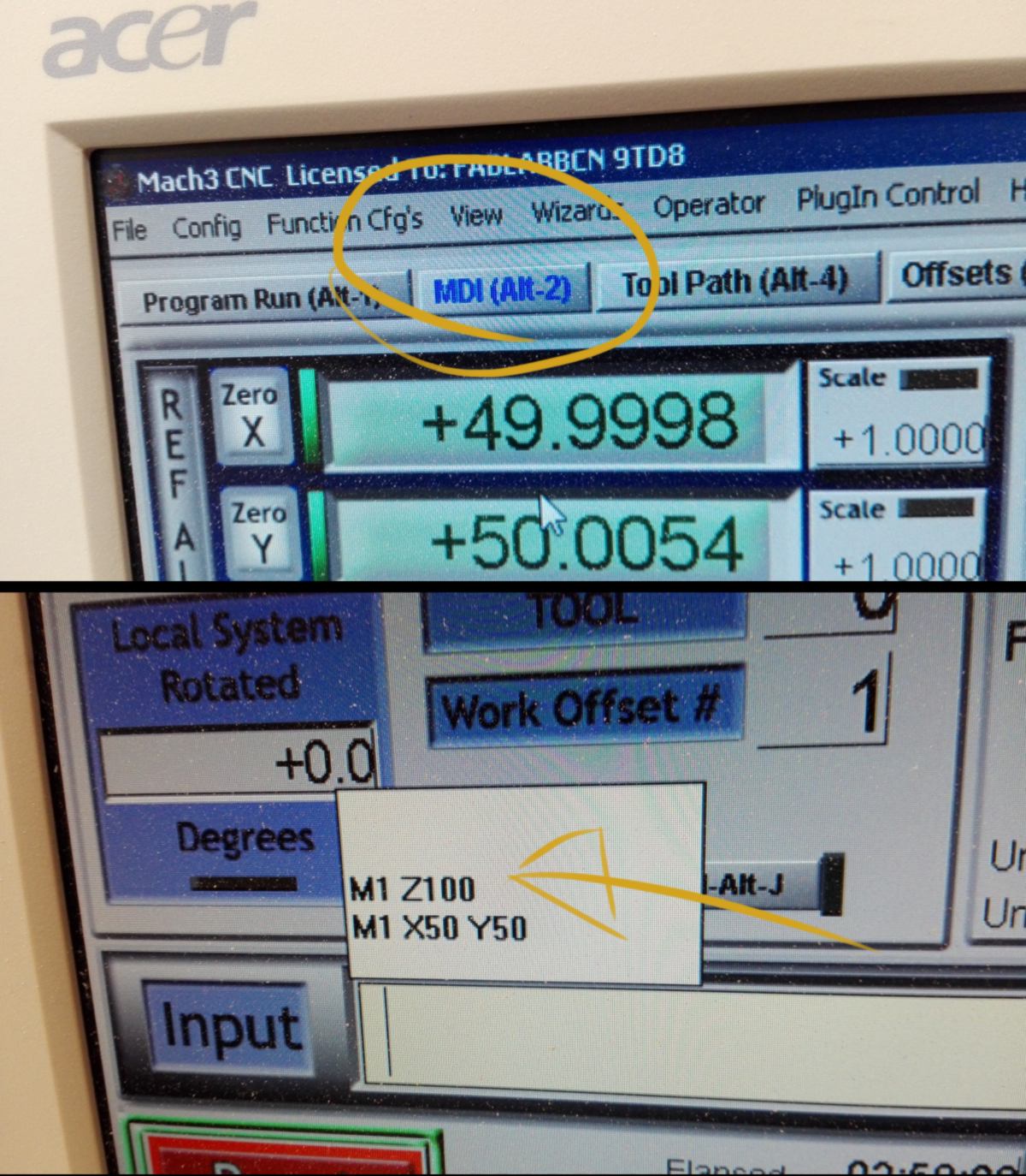
I wish to run a test, cutting the air, to figure out whether both my strategies and the g-code conversion are adapted to the machine. To do so, I wish to move the tool by exactly 50mm upwards, so that later on, I can move it back by the exact same dimension and get my origin in Z without having to recalibrate the machine with an end-plate. Joris shows us how to directly communicate with the mahcine by entering some very simple G-code. M1 is for motion, G3 for switching the spindle on and G 5 to switch it off. It comes very handy. We do a quick test and everything seems to work fine.
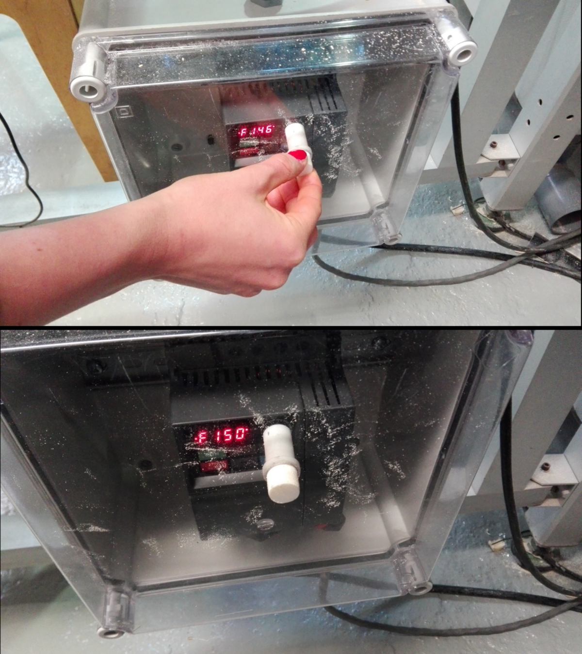
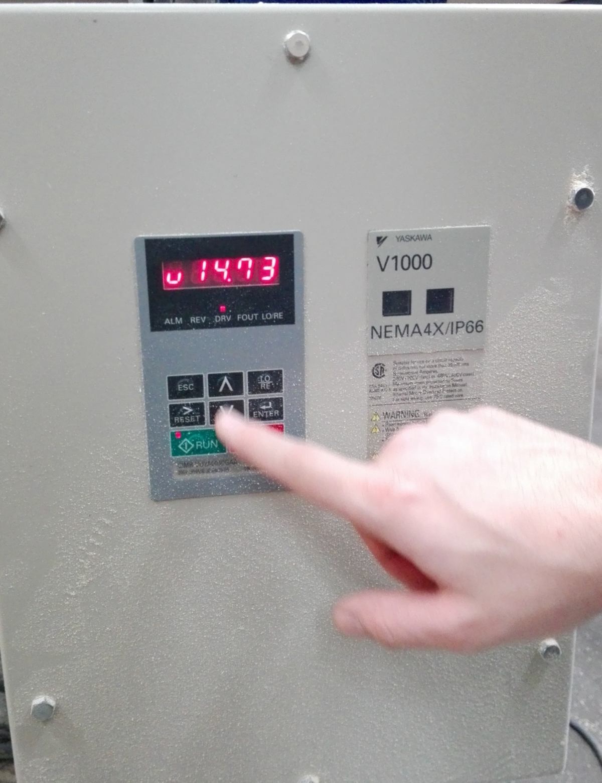
I happen to understand what issue this machine has (and what the technician has attempted to solve previously) : Mach 3 does not communicate with the spindle. I mean, not well. It can turn it on and off. Sometimes. The speed is set up on a separate hardware, with display the speed in hertz. 300 hertz equals 24000rpm, which is the maximum speed. We set it up at 150 Hz (12000). I know however that there is a mathematical equation to calculate the ideal speed for each end mill.
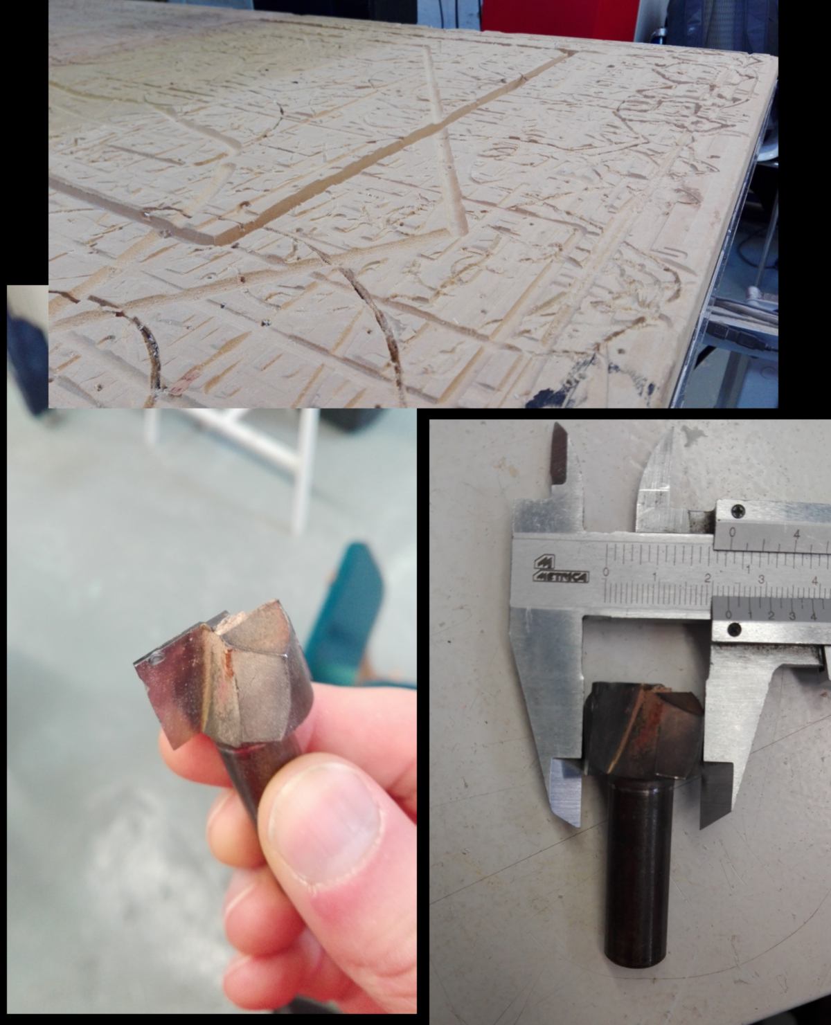
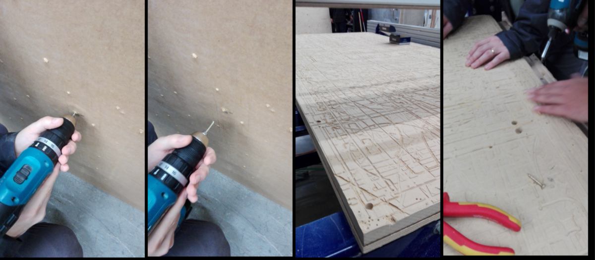
Sadly today the spindle refuses to get switched on. It takes many attempts and a few breaks to have it going. I have to switch off the machine and close the software many times, recalibrating my axis each time. I add this image below for future reference. I finally get it going, drill then screw two intial screws, then run a first cut, which drill 2mm deep/6mm wide pockets. These pockets are reference points for me to drill then screw in more screws, avoiding to screw on the path of the end mill.
I carry on with the proper cut. The pockets are being cut fine, however some of them are not cut fully through. I stop the end mill in the middle of cutting a pocket. It seems that due to the irregularities of the sacrificial layer, the wood has space to bend downwards without getting cut. In some other area, there is still a fair amount of material left, meaning the sacrificial layer is not perfectly flat. To avoid that next time, I will get back into my old routine and make the end mill go deeper than the thickness of the material for any cut through. For now I decide to adjust the height, lying to the machine by telling it that it is higher than it thinks by 0.1mm, which will make it cut a little deeper.
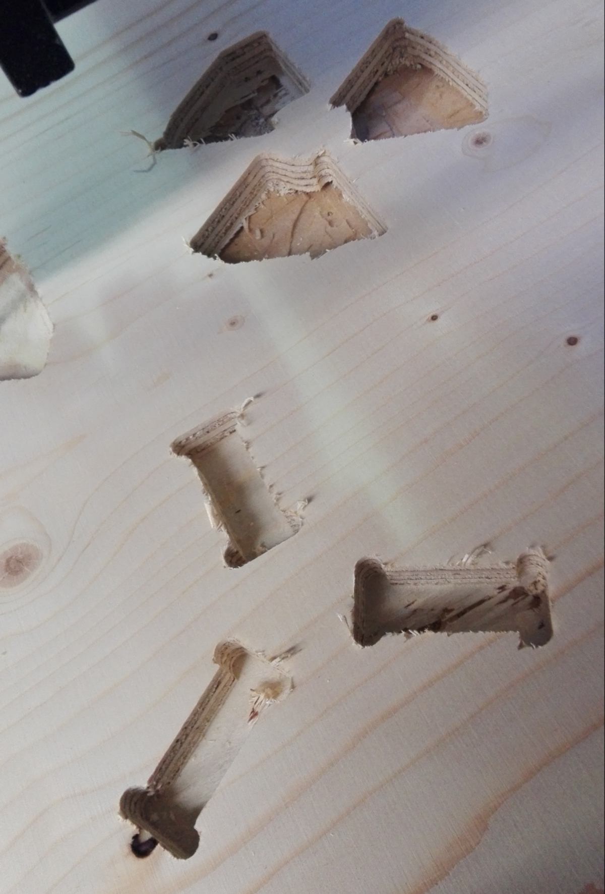
this is when, within a second of inattention, I break the end mill. With the intention to move the end mill up on the z-axis, I hit the Y-axis button. My end mill still half in a pocket, it goes sideways, finds the edge of my sheet of plywood, and snaps neatly, the tip of the end mill flying a metre away. Thanks protective googles.
This is definetely due to a moment of inattention, however... the controllers are also confusing. I have been used to move the CNC with the keyboard, where the movement in X and Y where plugged to the arrow, whereas the Z axis was plugged to the previous page/next page button. This mapping reduces the potential for error.
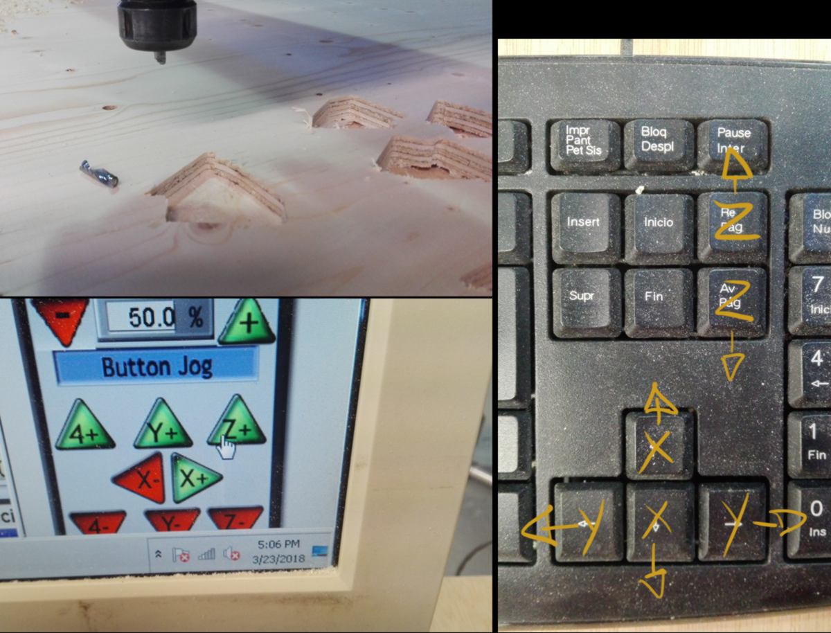
I leave the machine for today, hoping to set up these controls on Monday and avoid this confusion again.
With many down time in the CNC process, I move on a bit with my molding project. Firstly I go harvest a higher quality scan of the bark :
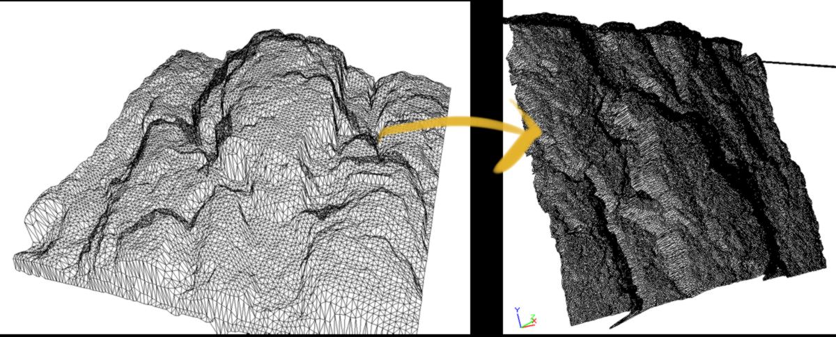
I clean it up, using a feature from Fusion that is under development, and only accessible by specifying it in the preference menu :
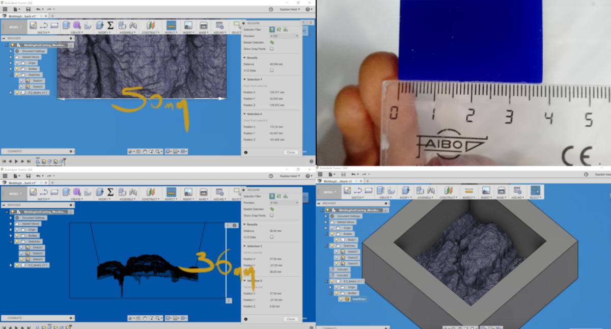
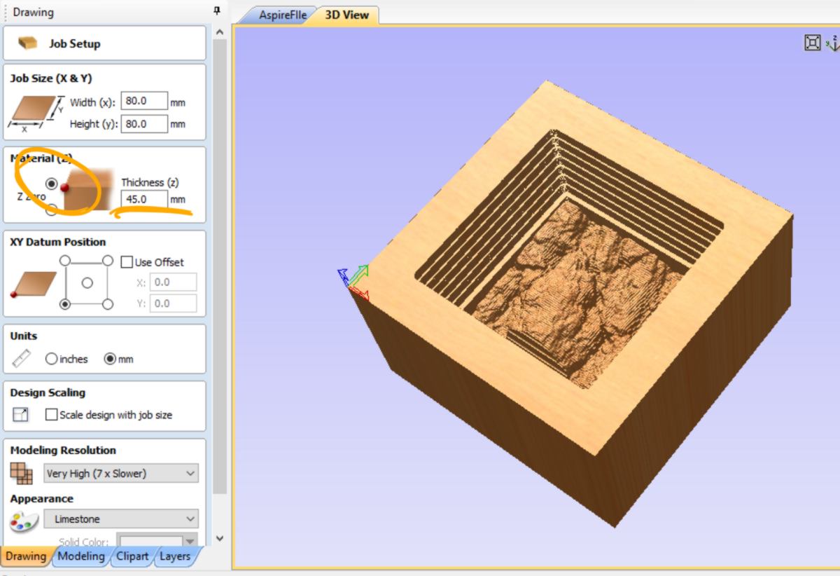
Then I rescale my model to the orginial size of the bark to be able to compare them. I also adjust the size of the container to make sure the scan fits neatly, deep hole (which won't be accessible by the tools) are filled up, and it will fit in the rectangle of wax we have been provided with.
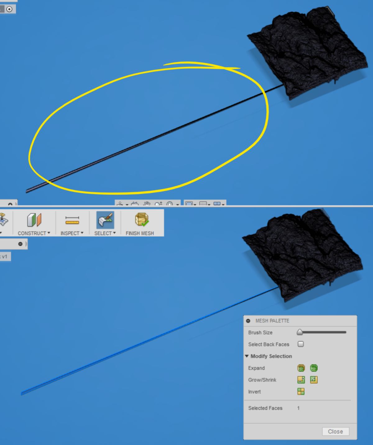
I then try to combine both shapes but, when trying to convert the mesh body into a native Fusion object I get the usual error message. I move everything into Rhino, where I will try to merge them later on.
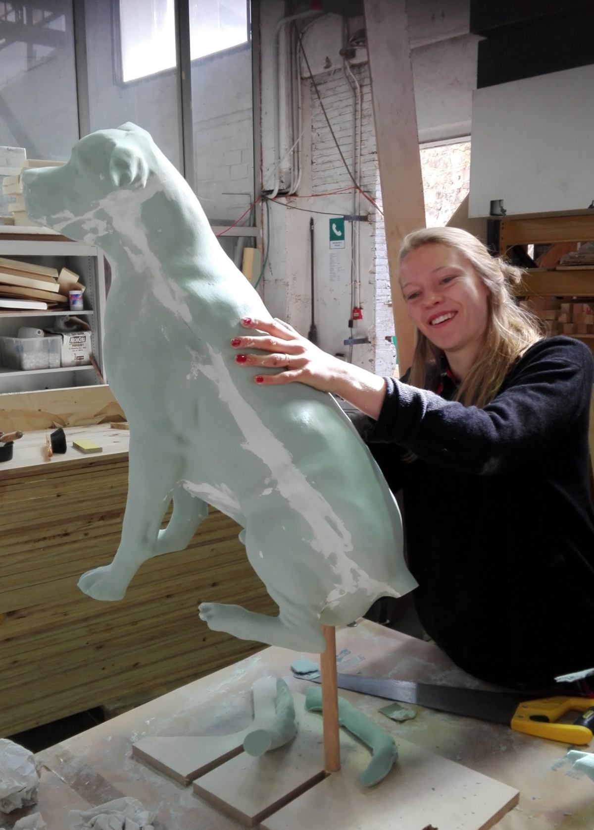
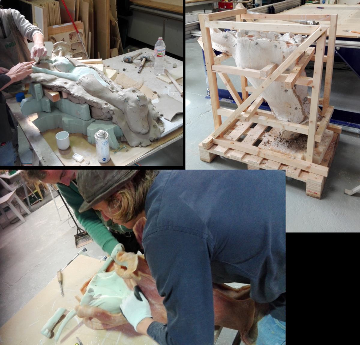
In the meantime, an interesting project is taking place, and involves some serious modling and casting. A real scale dog is being shaped on another CNC, and will be molded then cast many times. These will be set up all around Barcelona, attached to a lampost, and are set up to raise awarenes against people abandonning their dogs attached in the city.

25.03.18 /Design doing. For good or not? This is the one liner of the new exhibition at the museum of design, exploring ethical choices that designers face. The exhibition is also a gigantic data collection system : each visitor receives a swipecard they use to answer questions along the exhibition.
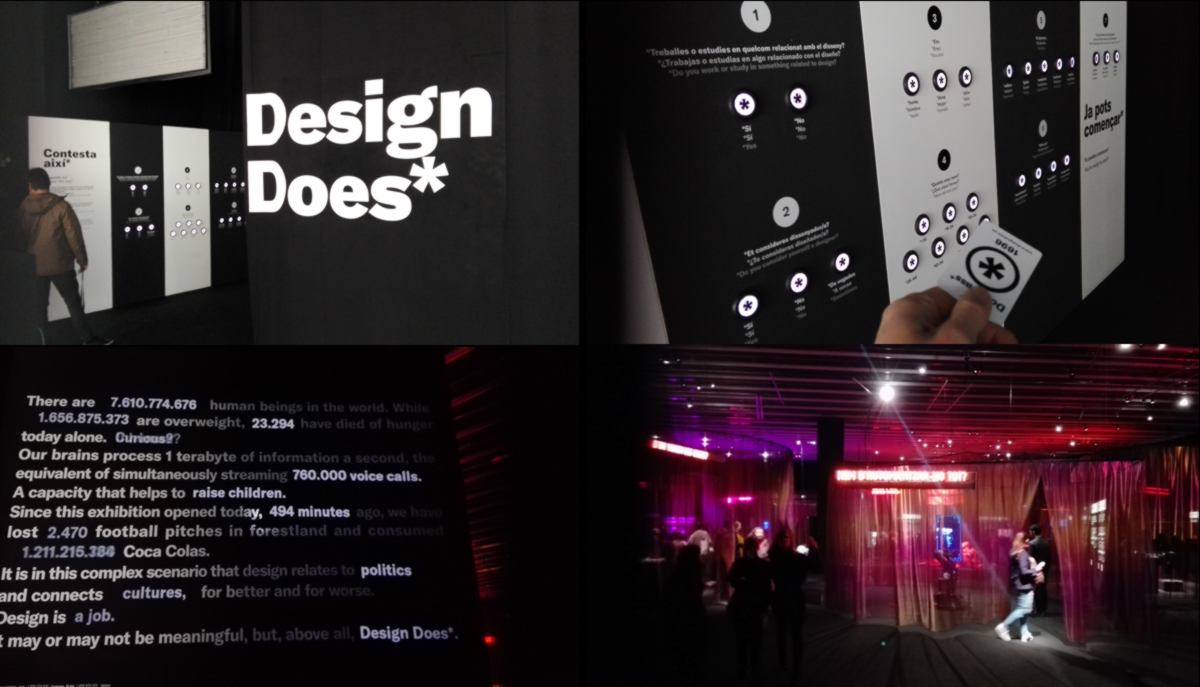
I was surprised to see that, when it comes to automated border protection equipped with machinegun (currently setup on the border between South and North Korea), 79% of visitors blamed the designer rather than the government for its installation.
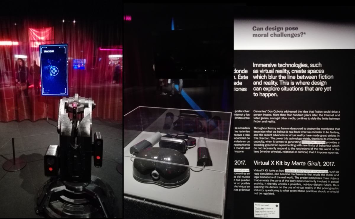
Designers define behavior to a certain extent, but at some stage, should we blame the technology rather than the decision makers in case of bad judgments? The conversation is ongoing, especially considering the ethical programming of self-driving car in case of accident : would the program have to choose between killing the driver or pedestrians, who will it choose?
26.03.18 /Back into the design of shapes and strategies prior to molding. before we get into this, I must update you on two things :
a new strategy has been set up and I am ready to give another go as soon as we get our new delivery of end mill :

We have a new pet at the lab, now standing tall, almost ready for a mud bath:
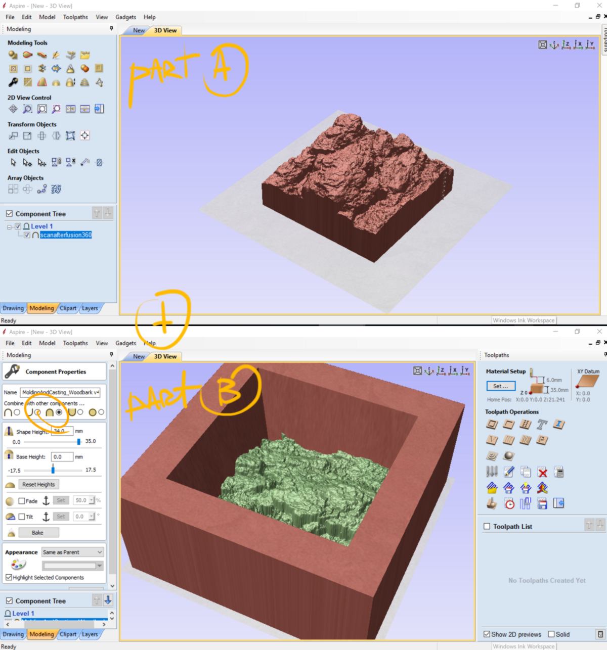
After a last attempt at combining all my pieces in Fusion360, I decide to import them all in Aspire and merge them there :
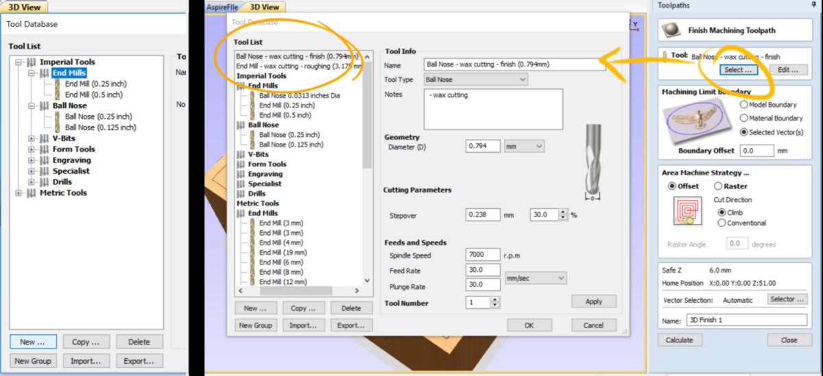
Before planning my strategies, I must create the two tools I will use. They are missing from the list. I defines the basic parameters (type of tool and diameter) as well, as the ideal stepover, depending of the level of quality I want. For example, the tool used for the roughing step will have a rather large step over, whereas the finishing step, using a ball nose, will behave the opposite way.
To populate the other areas, I base my data on what has been set up in Modela player 4 by my tutors :
To be able to mold the negative which will result from this molding the milled piece, I must add borders so the material will not overflow. I create a shape in Fusion which I add on top of the two others.
To shorten the milling time, the finishing step can be only applied to the shape rather than the entire mold. I set up a new vector to define a surface for it :
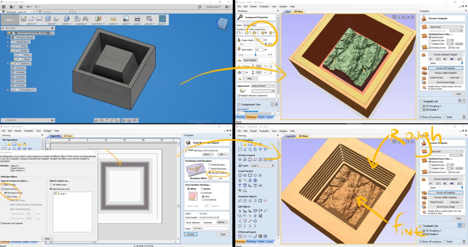
The wax we use is uneven on the top surface. Rather than setting up the zero on the workplate and risking to have my end mill hitting a part of the stock that is popping out, I will set up the zero on top of the stock, at the highest point, and drill down from there.
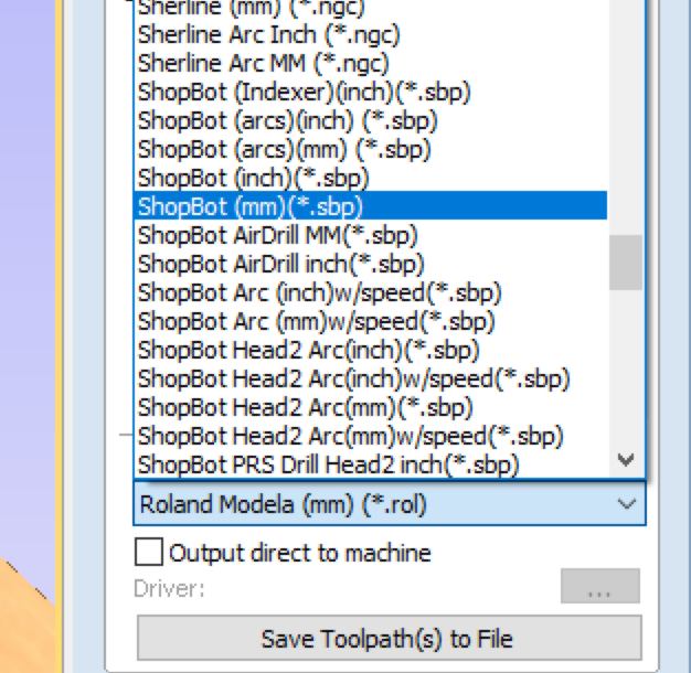
Exporting the G-code, I attempt to use a .rol filetype, since no smr-20 can be selected by default. When loading, the SMR-20 sends a distress call :
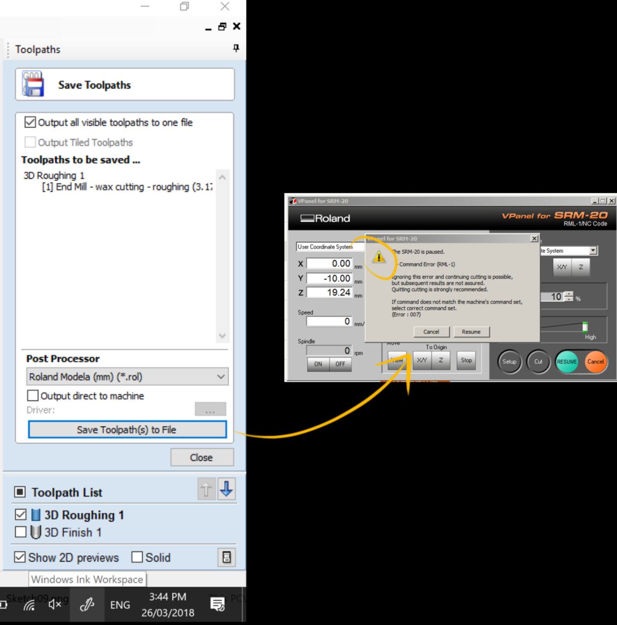
I do not wish to make a havoc in the precision milling room, since so many of us right now need the machine, so I cancel the cut, and look for a way to import the SMR-20 in Aspire. And find no ways to do it. Both Google and Aspire User manual returns the same answer :
I am certain there is a way, I simply cannot find it, so I decide to move on to prepare my strategy with Modela player 4. Luckily I can export an .STL from Aspire :
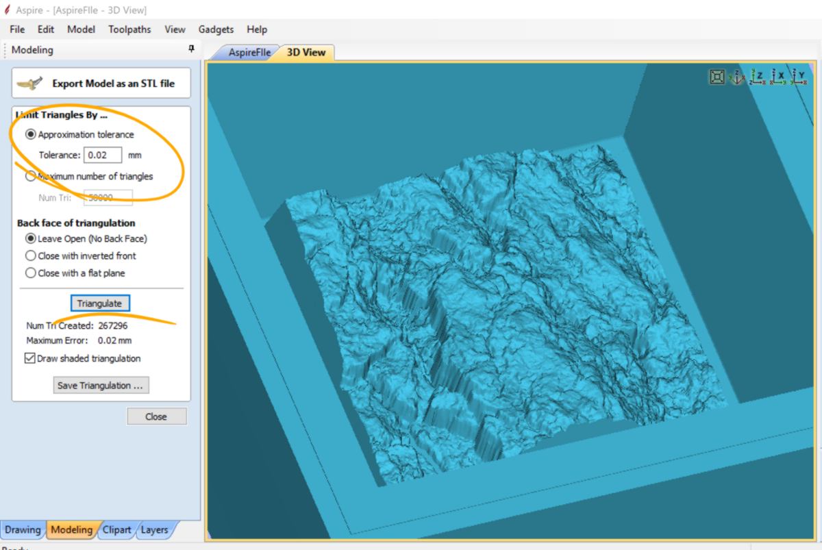
I go through the same process: setting up the stock and origin, setting up new tools, setting up roughing and finishing step, and exporting the gcode, this time in a format that is compatible with the SMR-20 :
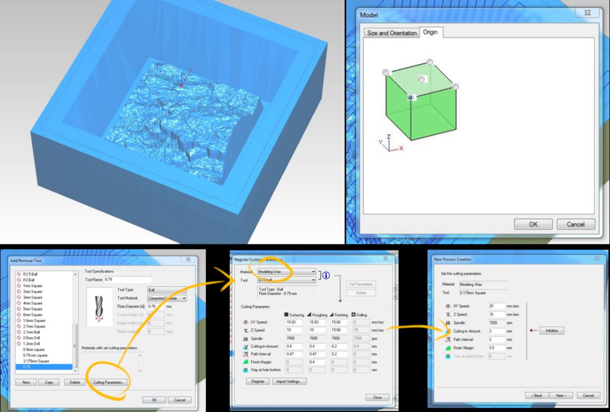
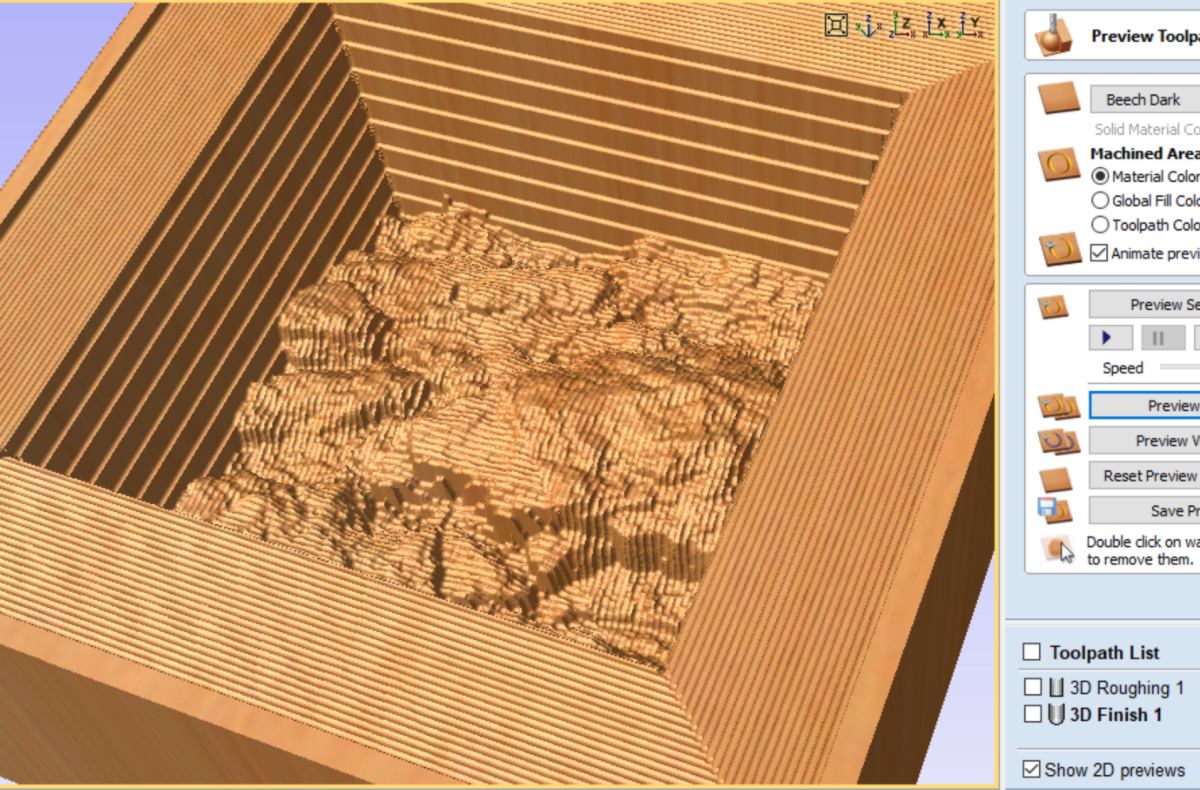
I gather the 3.175mm end mill and the 1/32 ball nose for my cut, and run the roughing step. I vary the speed directly from the software, and learn that if the velocity is too slow, the wax melts and stick to the tool, and that if it goes too fast, it puts too much strain on the milling machine which switches off before breaking. I end up finding a sweet spot in the middle.
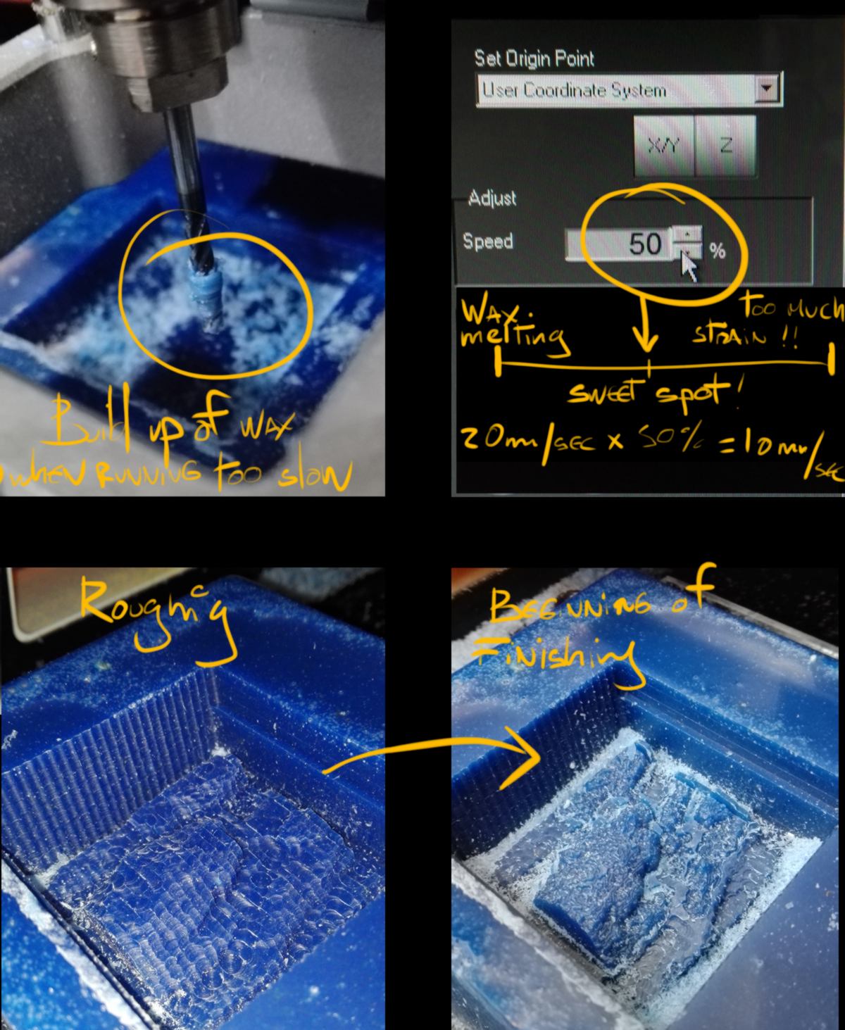
I use the same speed (10mm/sec) and launch the finishing strategy. I will let it run overnight with no supervision, that is why having the right parameters was important. I adjust the speed accordingly. The speed was set up initially to 30mm/sec, so I adjust the speed at 33% for the finishing strategy.We will see the result tomorrow.
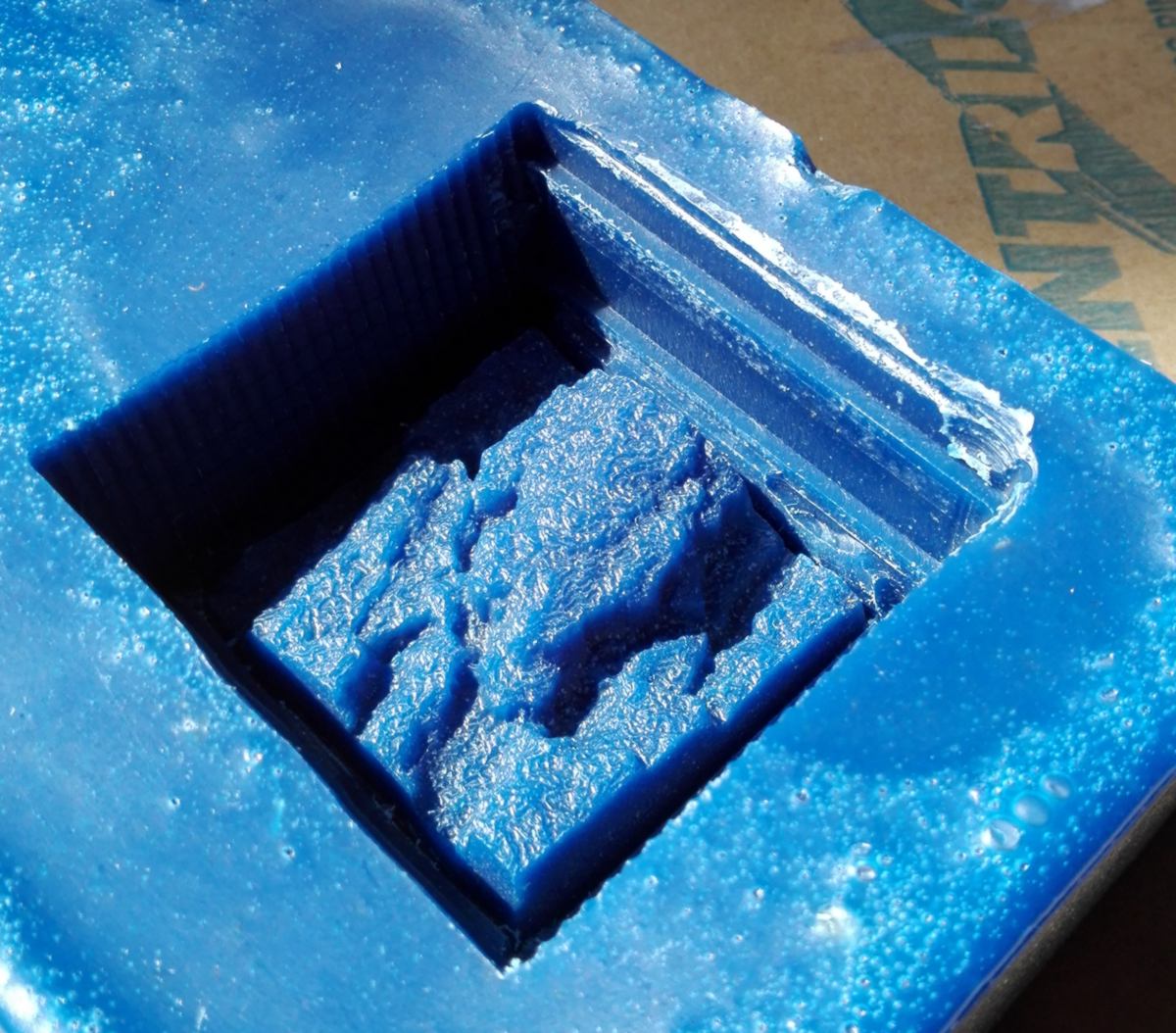
27.03.18 / The precision milling machine has worked well overnight :
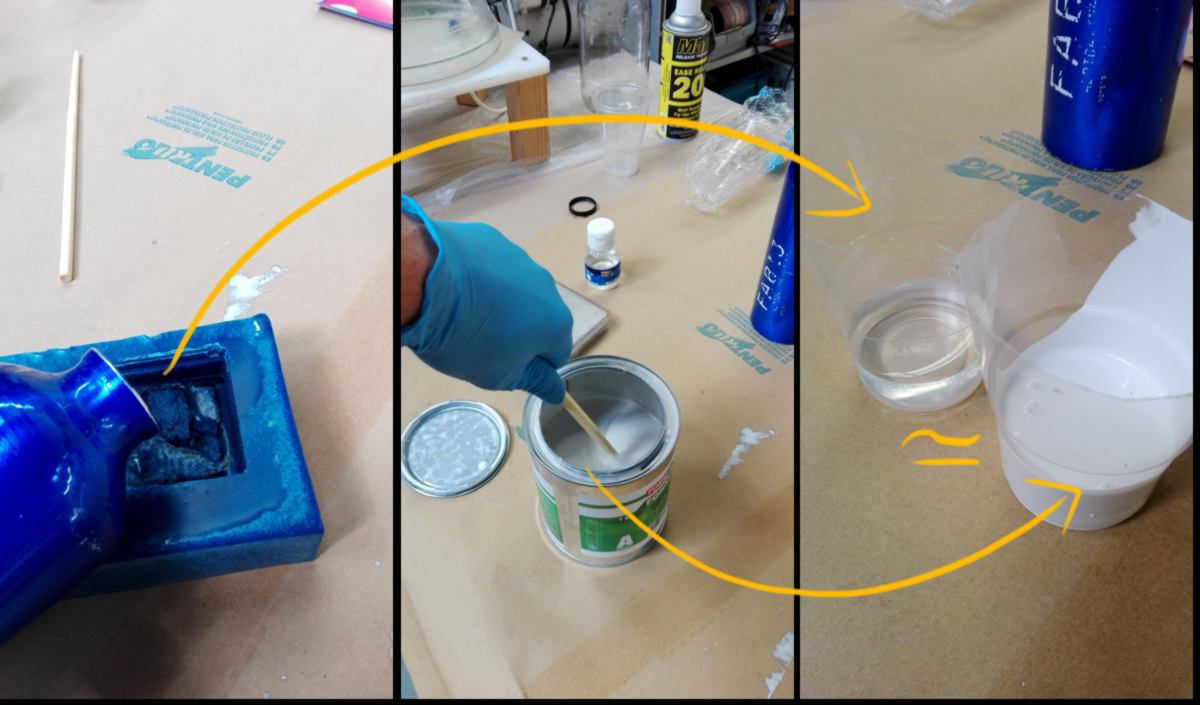
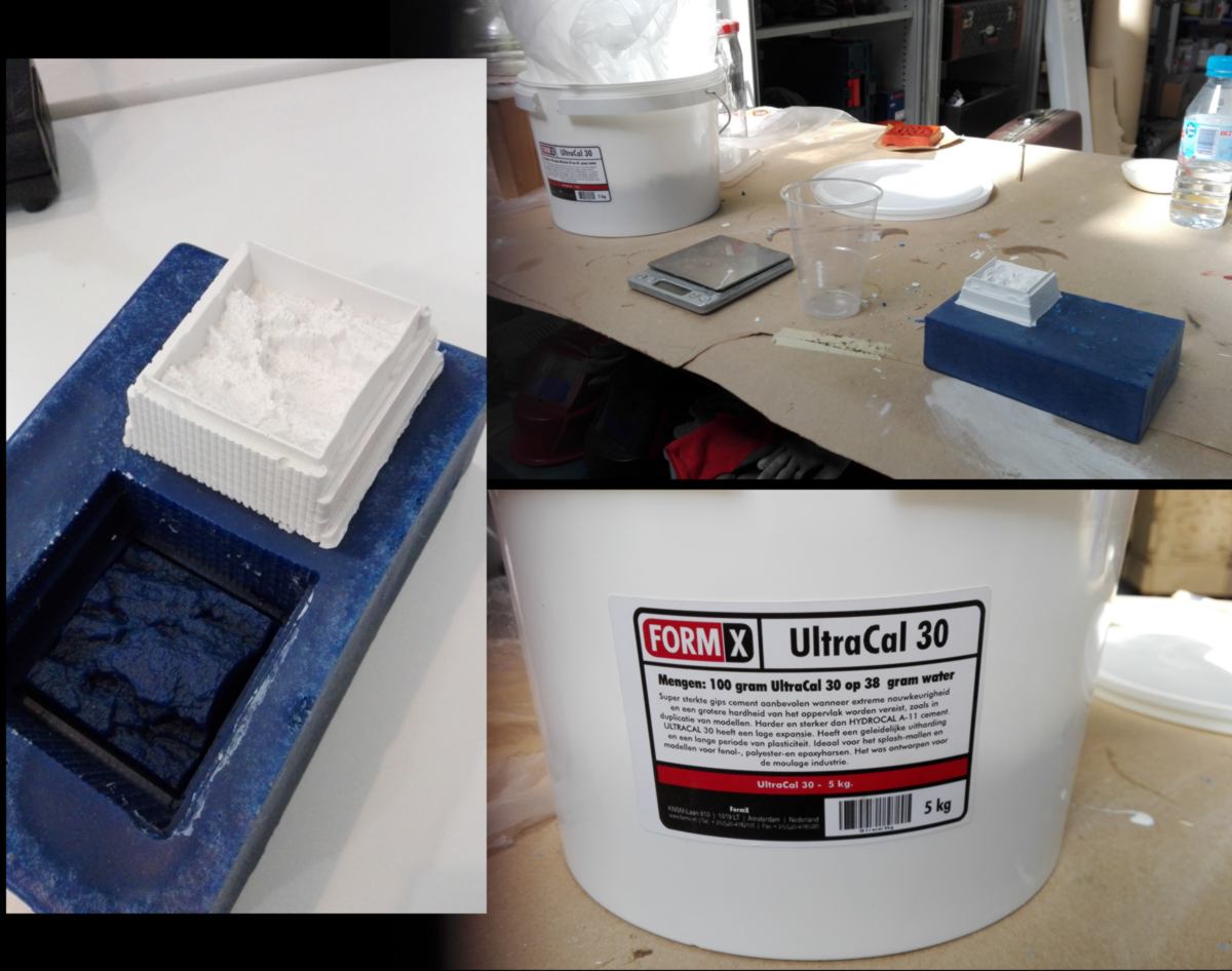
I gather the safety material and molding material necessary for the molding process :

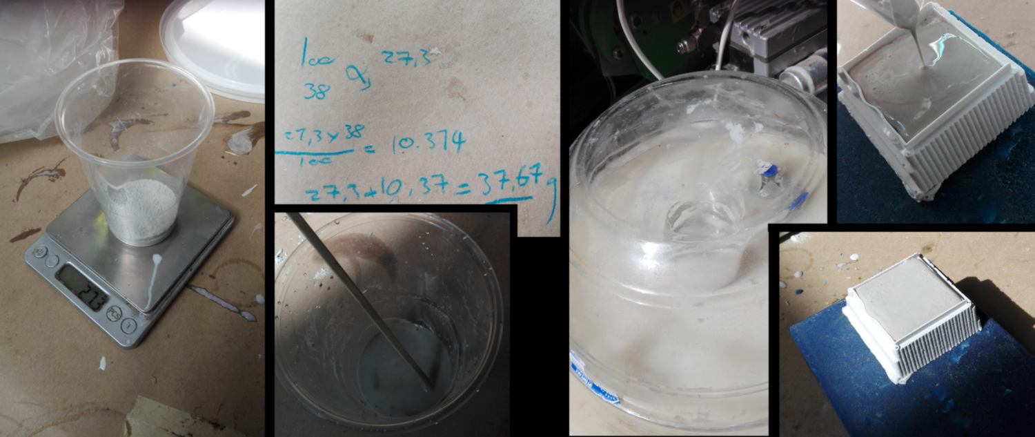
I calculate the amount of silicone required to fill my mold :
I then plan to add 5 percent of binder, but the balance displays random weight change :
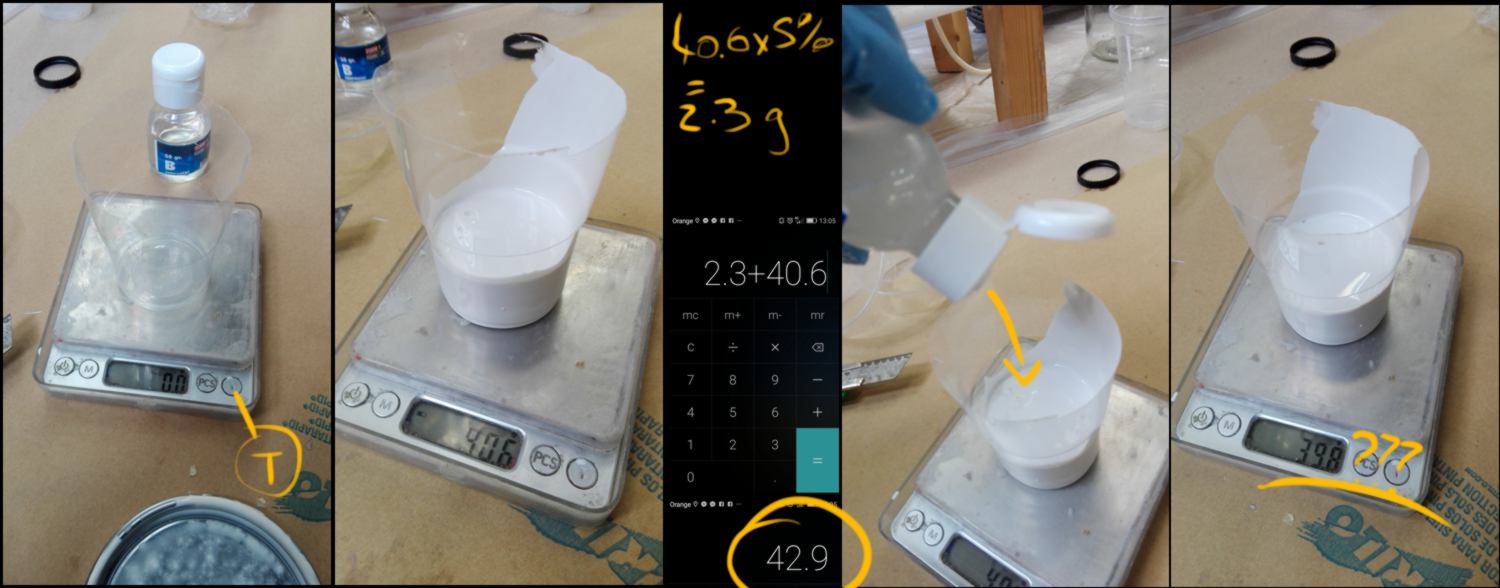
I re-weight my whole mix later on to find out that I have added 2.7g of binder, which is 1.6 percent more than I was aiming for. We will see how fast it hardens.
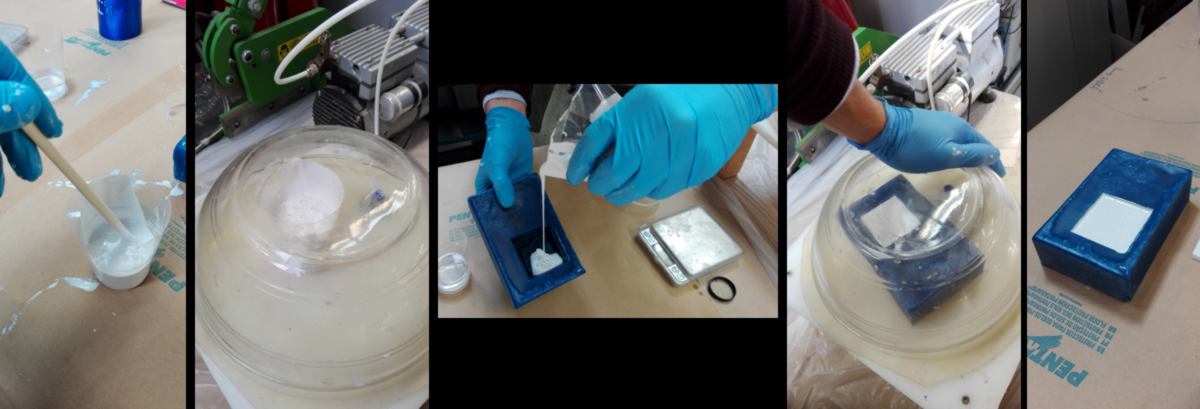
I then stir the mixture, use the air compressor to get rid of as many bubbles as possible and carefully pour it into my mold. I use the air compressor again and insist on reducing the amount of bubbles to the very minimum before leaving the mold to dry. We will see tomorrow how it looks.
In the meantime, both CNC have become out of order. I will await tomorrow to use another CNC at the IAAC building. It is a shopbot, so I have to re-export my strategies in another format.
28.03.18 /Milling time! I have my files ready to cut the test for the joins. I first need to export the Gcode in the right format. I will use a Shopbot today :
This morning a student has been using it without setting the sacrificial layer. The sacrificial layer had been taken off by another student who needed more height to carve a mold (the dogs you saw previously). He also used the wrong size of philips screw driver and cammed out of some screws. A lovely video explains that and a lot more there. We cannot unscrew some, so we cut the wood around it to unscrew them.
We then set up the sacrificial layer. While moving it, we notice a screw in it. It has been cut from the top, and is stuck in the material. When flattening the sacrificial layer, this screw is likely to cause damage to the end mill, so we take it out. We make some new holes for the screws since the last ones are not in good condition, and screw it all back.
Ideally we should flatten the surface but we do not have the tool (and the will) to do so, so we move on. Full disclosure, this Shopbot does not have any automated system to set up the origin on the Z-axis, so we do it by hand. Since the sacrifical layer might be curved, we set it up a little into the sacrificial layer, all by eye.
One more specificity of this tool : the speed of the spindle is set to 14000 rpm/m and cannot be adjusted, either manually or through the software. It is a good test.
We run a test file, up in the air to check the gcode, then run both jobs : one for the screw, another for the cut. The spindle must be switched on separately.
While cutting, I go through the screws available and get rid of the mounted ones :
At the end of my cut I inspect my sheet and make notes for everything that needs modifications, or brings up interesting pieces of information :
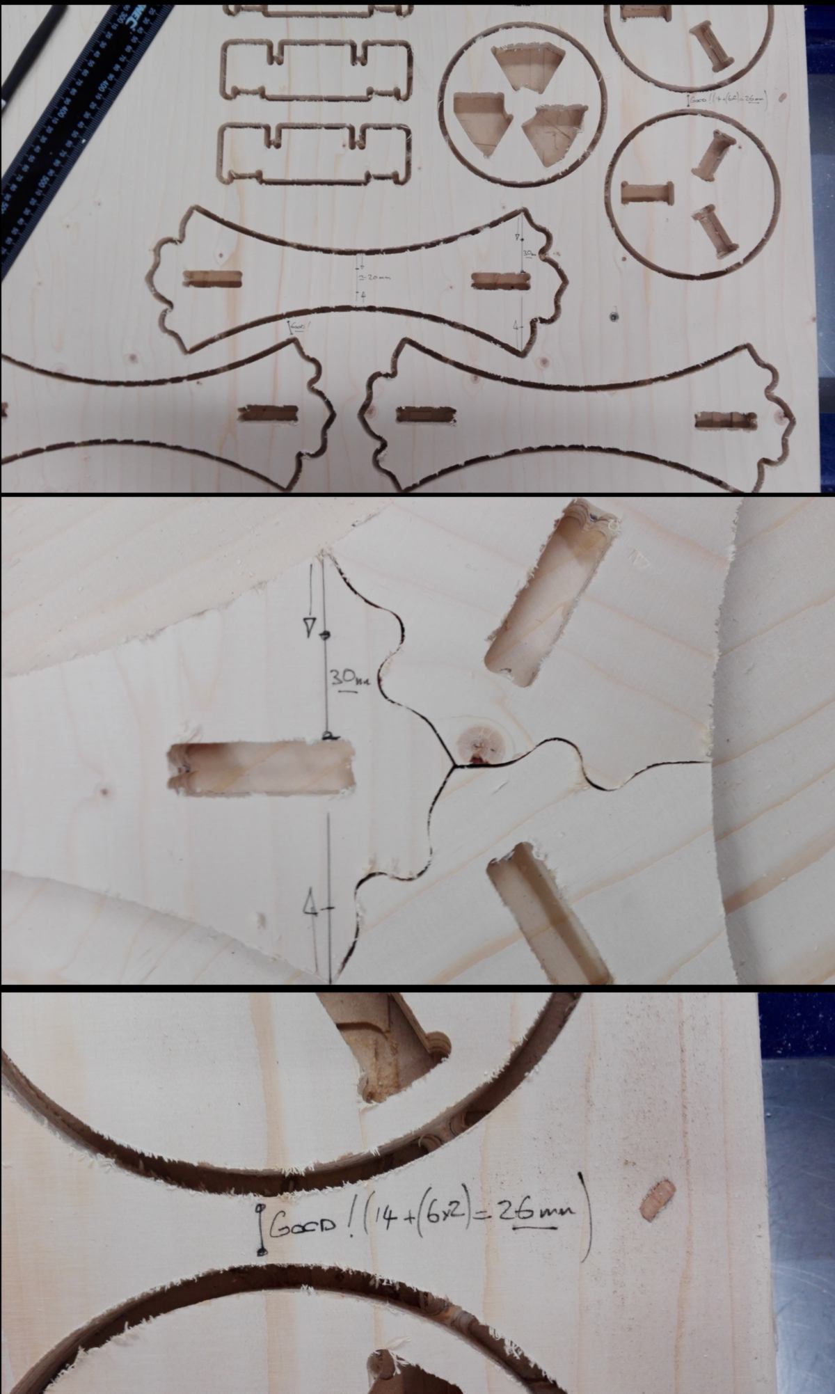
I hammer one of the join together - the only one that is meant to be tight. It needs a little adjustment, too tight. Also, the height at which the end mill moves above the stock is 6mm. It is fine when the stock is screwed in. However in the first step (when the end mill marks the location of the screws) the board is bent and might get in contact with the end mill, possibly getting damaged. I must adjust this height for my next cut.
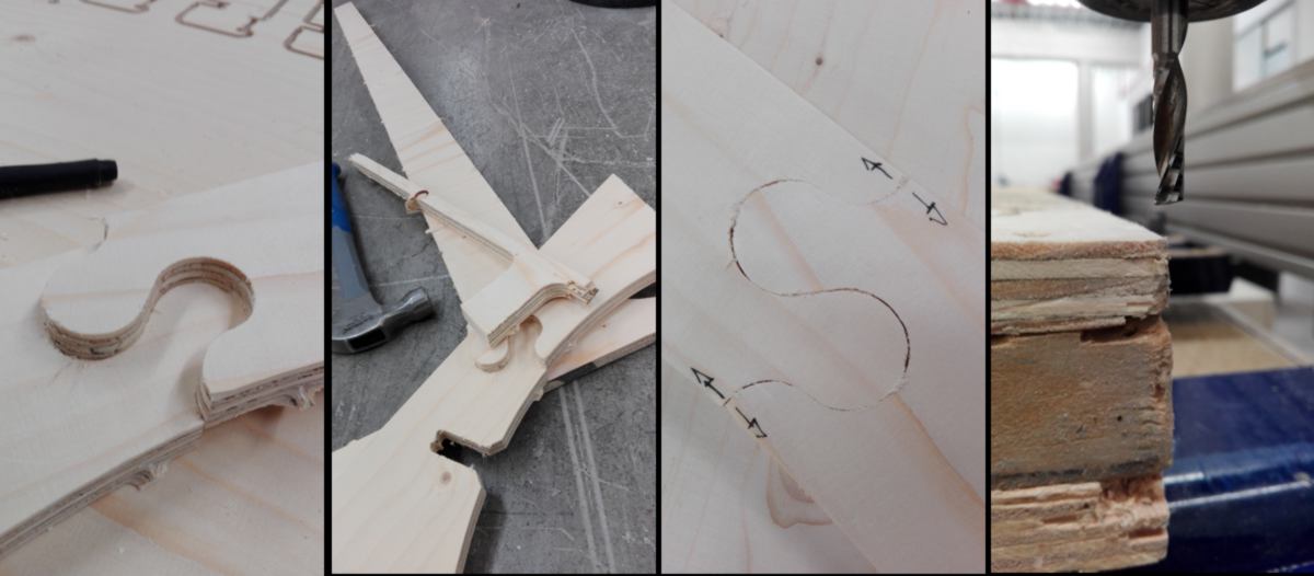
I take the other parts off, push them together (they fit very well) and take notes about what must/can be modified. For instance, the "wriggle join" needs modifications :
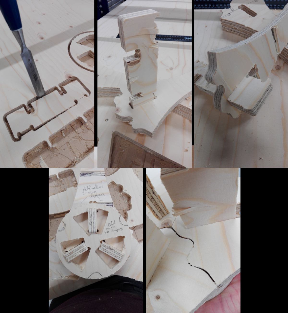
to complete the test, I cut three more pieces and put it together. I add notes to the design again :
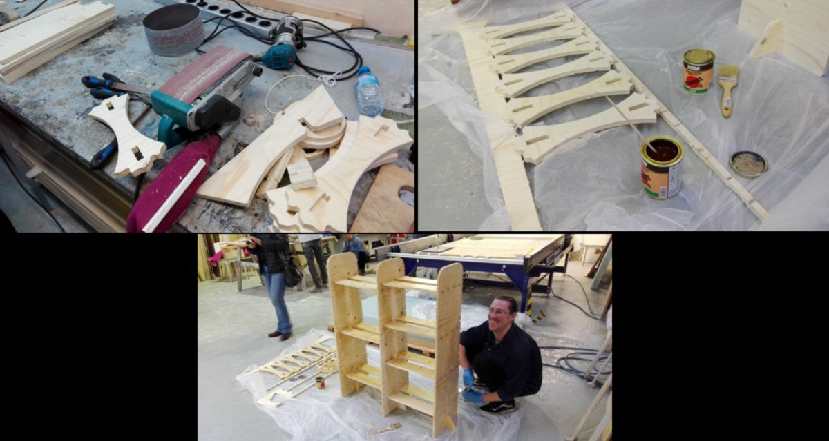
I go to the workshop to sand and varnish each pieces. I wish to see whether varnish will change how pieces fit together, and how much. In the meantime Daniel has put together a piece of furniture that does the same thing as mine, in a simpler way :
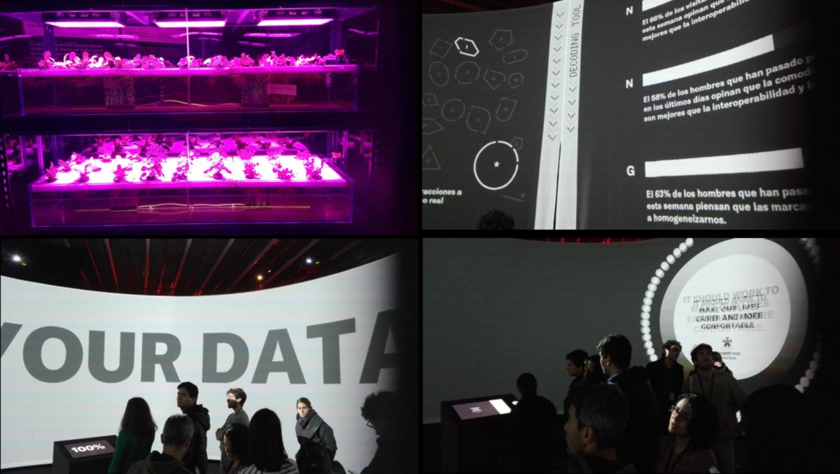
I have recently bumped across a video of an automated hydroponic system that sets the standard of efficiency. I realise again that the design I work on is a good learning experience but in no way a productive system. Oh well.
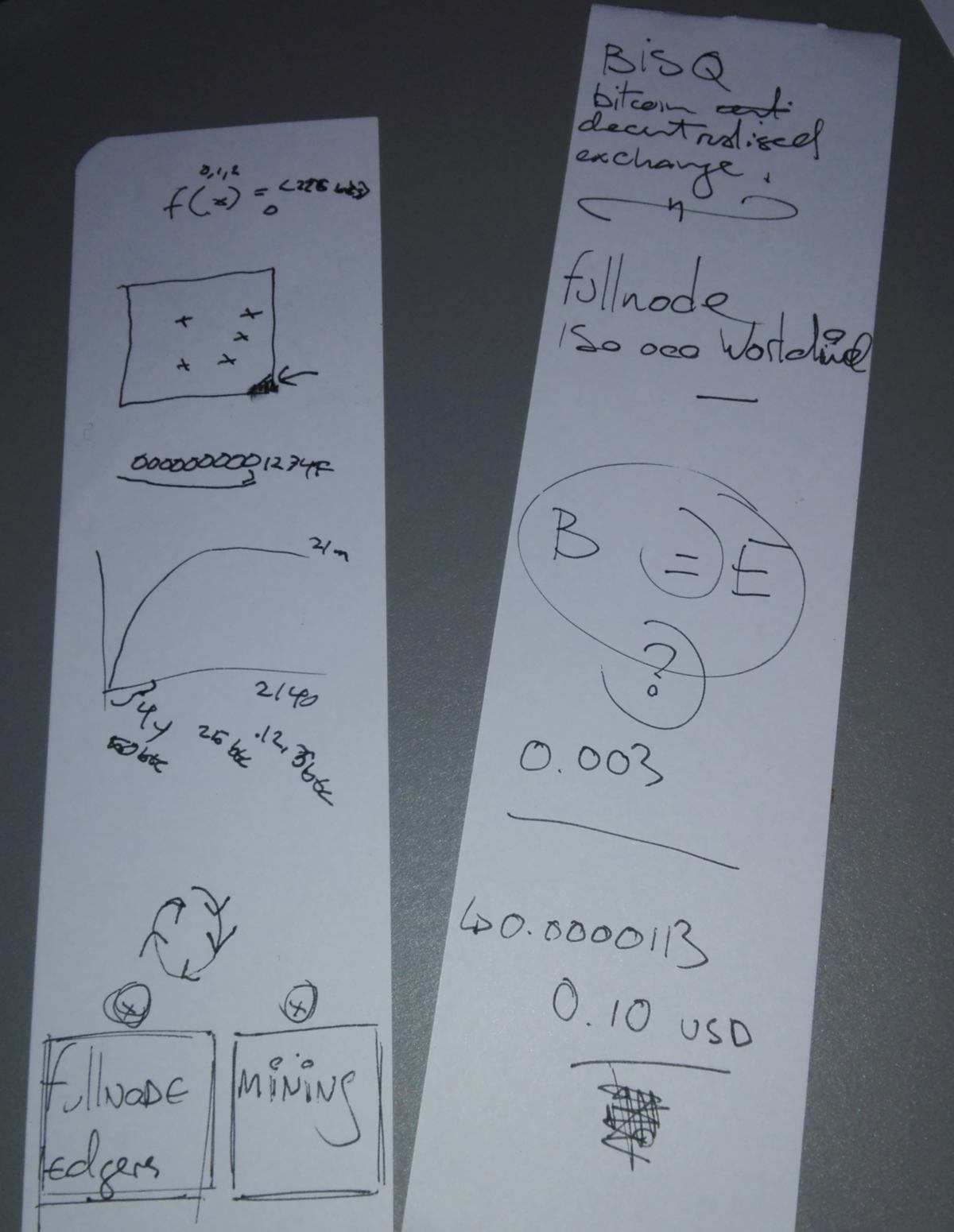
At the end of the day I went to a cryptocurrency workshop. We set up a Wallet with Samourai wallet and made some transactions both ways. For the first time, someone was able to describe to me precisely how the Bitcoin system works : what is a fullnode and what it does, what is mining, what is does and how it does it, what fees are attached to each transation, how much it is now and how it will be in the future.
We had a conversation about the hardware used for mining and why it is close to impossible to make any money mining due to the fierce competition in mining. We also talked about how the system regulates itself, and how fullnode owners can influence the size of blocks and perhaps modify the amount of transaction performed in the future. We discussed about the limitation of the bitcoin system, and why it takes so long for transactions to be validated. But we also saw how simple it is to transfer money regardless of our geographical location, and without middlemen.
Below are some notes from the workshop. The scope of it deserves more explanations, and these are not fitting in any documentary that I had seen before. It was time very well spent, thanks to all people involved.
29.03.18 /Today is quiet at the lab since Friday is off. I attempt to put my test together. With the varnish, all pieces are thicker, and it takes some hammering to put them into place. I learn that you assemble first, varnish later. I also makes some notes about how the design could be adjusted :
Mikel is setting up his homemade 3d printer. He has designed it to be sturdy for the intensive use of the lab, and modified the use of the motor. To avoid overloading one single motor, he has been inspired from a system in which both motors work together to move the printing head in x and y axis, constantly sharing the load. It is inspired from how delta printers share the load of the print in all axis.
After 48hours in the mold, my silicone has still not fully dried out. Meanwhile, the thin cast Dorotha has made using the same mix has been casted out and used. I think the depth of my mold make it longer to dry. I will wait until tuesday and see.
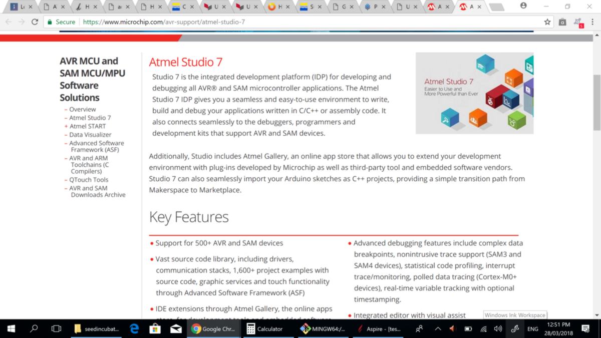
I look at how to bootload/program my boards with my Windows computer and, following loosely tutorials with broken links on the fab academy website, I bump into Amtel Studio 7:
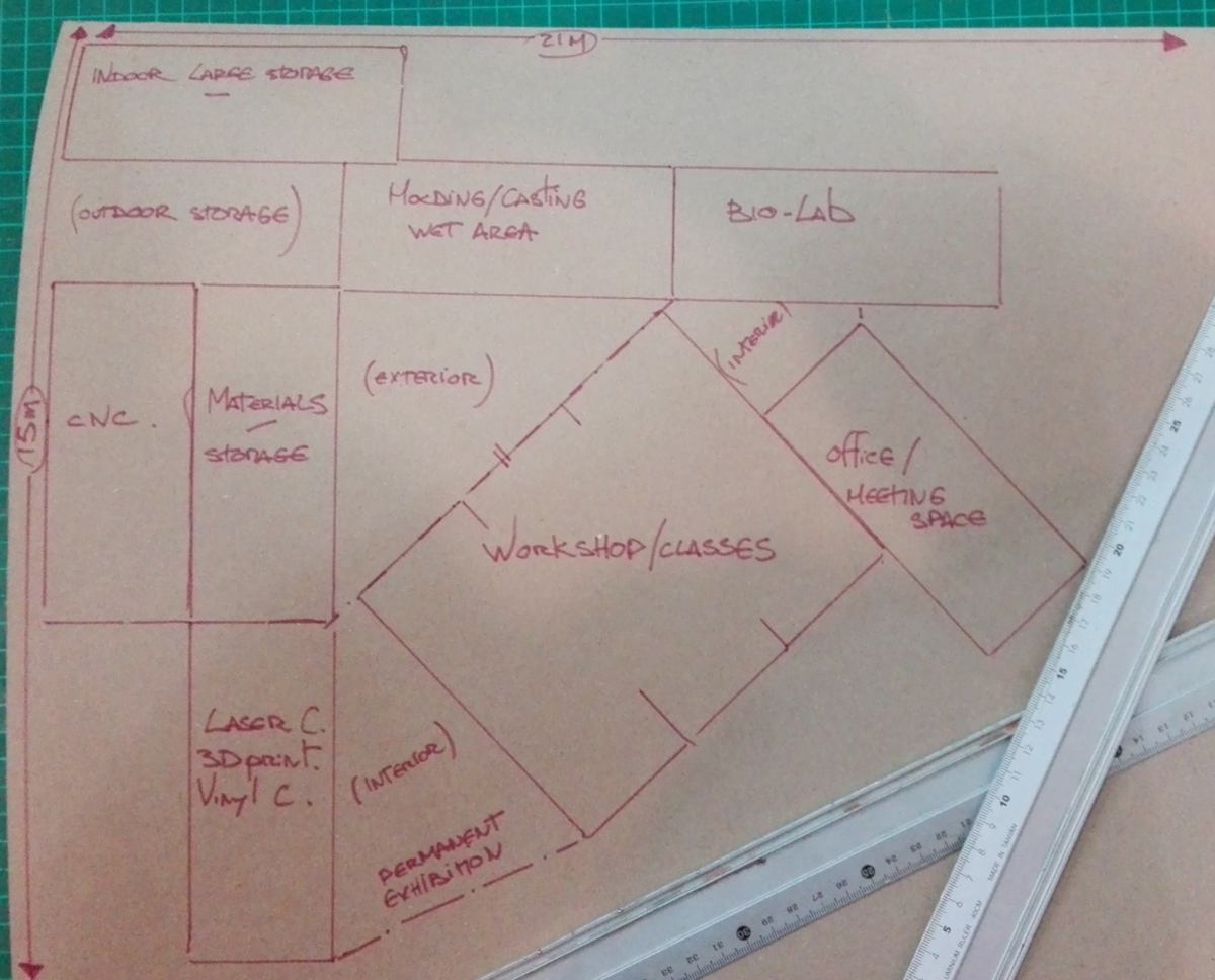
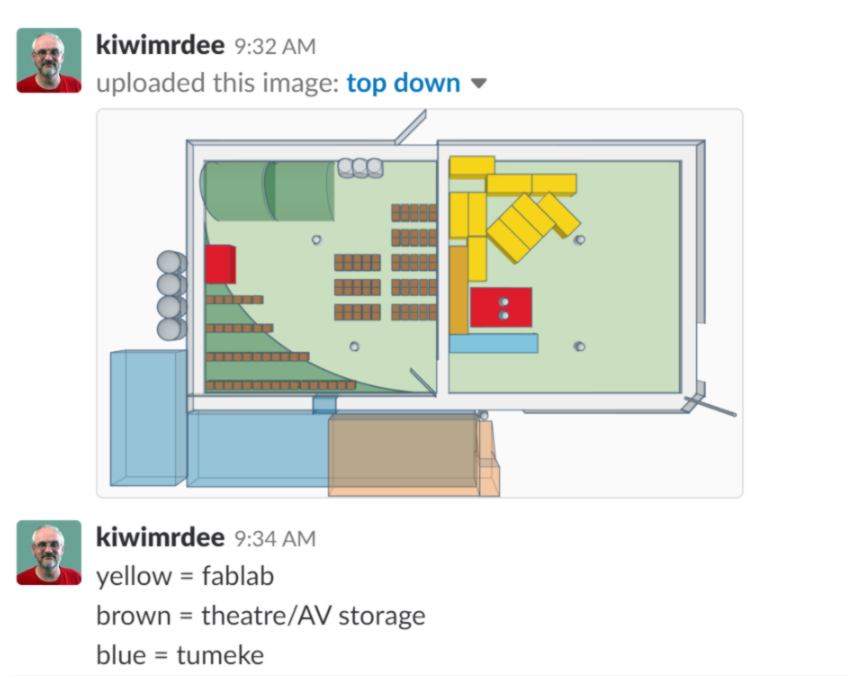
For now, I MUST focus on funding application for Fab Lab Auckland. The deadline is tomorrow 9 am. The difficulty is to know what to apply for. I think prior to any machines, we need walls, or, in this case, refurbished shipping containers :
30.03.18 /Fab Lab Auckland is in sheer need of a website. In order to share the concept with as many people and organisations as possible, including collaborators, I need a place where they can read in depth about the project.
I have learned from this website that being mobile friendly is crucial. To make appealing content on all devices, I am considering using Bootstrap.
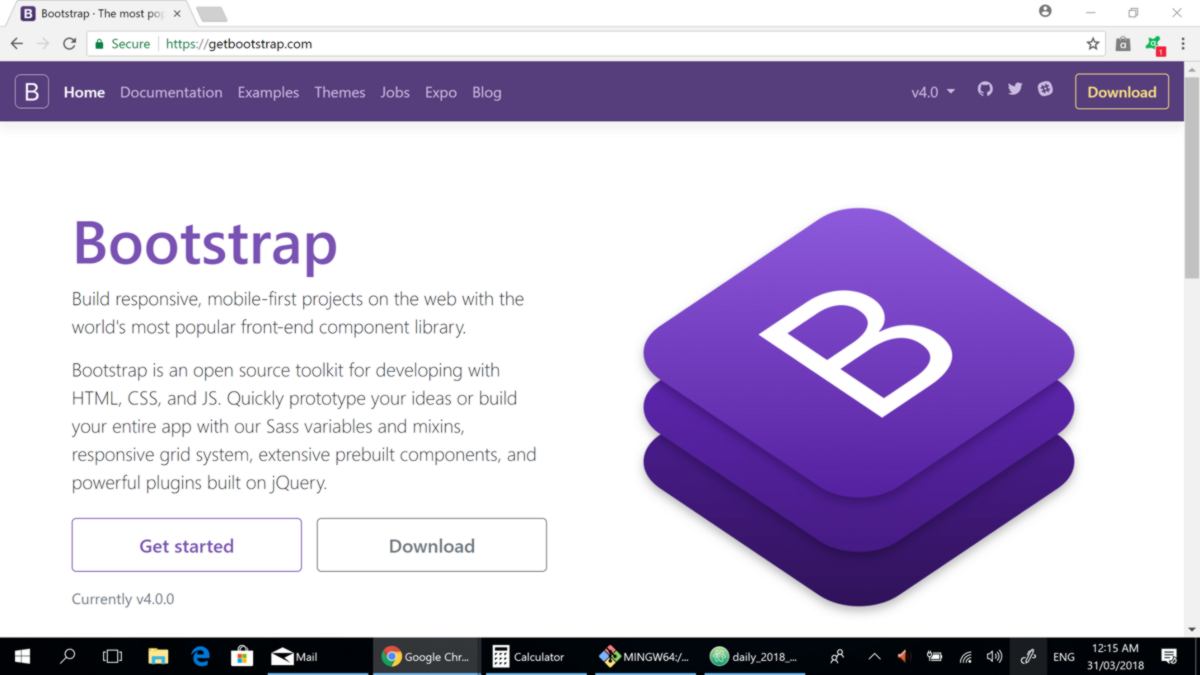
What Bootstrap offers is a list of pre-made CSS and Javascript ready-for-use, so websites can look pretty, and I can focus on content rather than style. Hopefully this will be a huge time-saver.
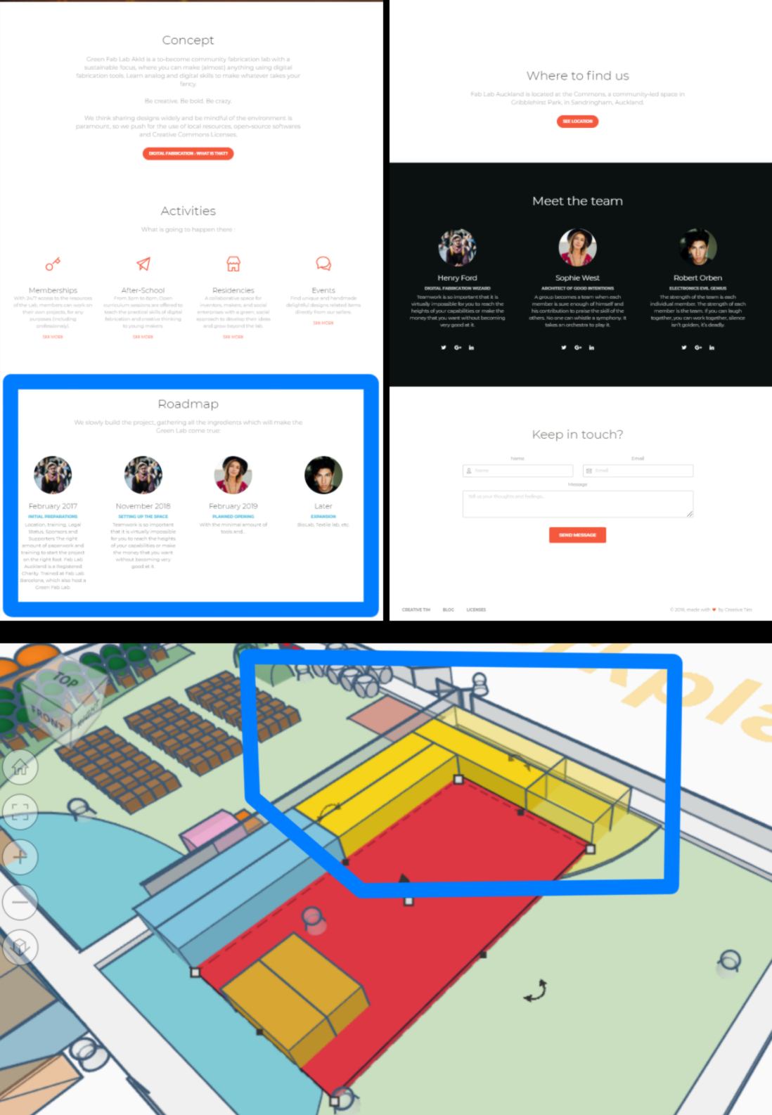
What Fab Lab Auckland requires right now is a picture, a brief explanation about what is does, a description of our future projects/services, a description of the team and finally a way for people to get in touch. I found just that in one of the free example designed by Creative Tim:

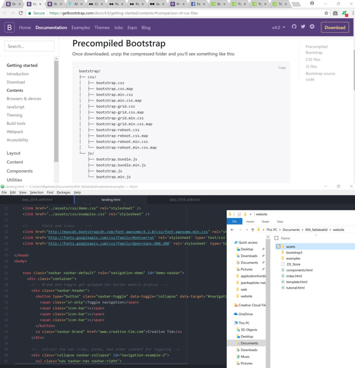
I learn about Bootstrap simply scrolling through the html code as well as the folder hierarchy. It is neat and very-well annoted :
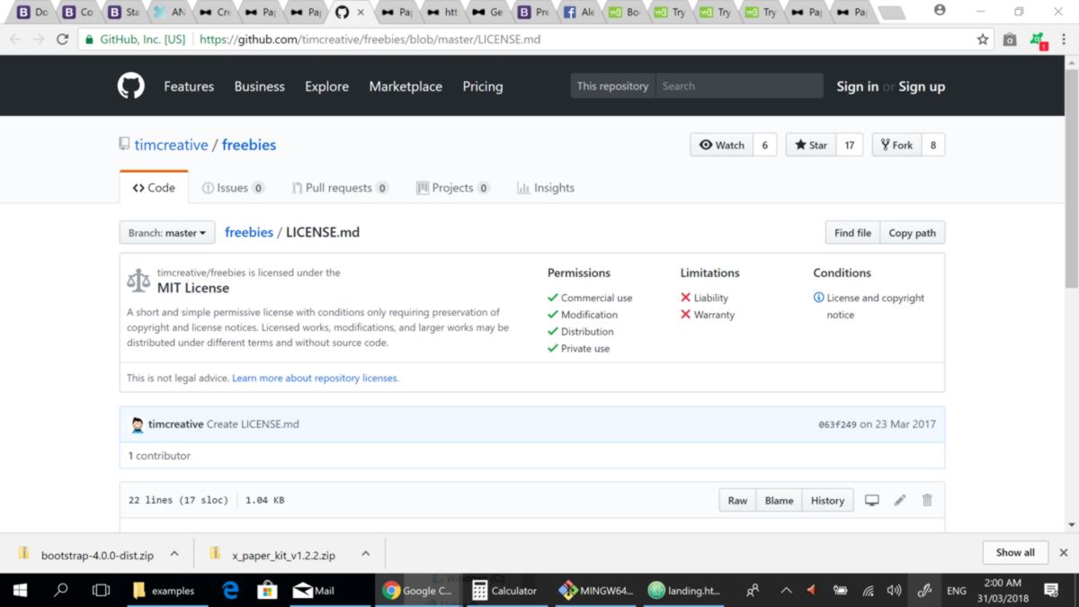
I contact Creative Tim to figure out how to use correctly their work without Licence infrigment - (MIT CCopyright):
Another person in charge of the overall space at "The Commons" ( the community space where the lab will be set up, fingers crossed) has designed a render of the space. The lab is in yellow :
I am in touch with them to write a MOU and lock in this space.
02.04.18 /Lets read about the danger of molding and casting. I go through some documentation about different material used during these processes:

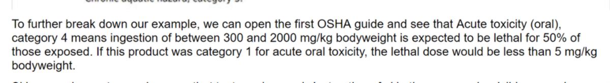
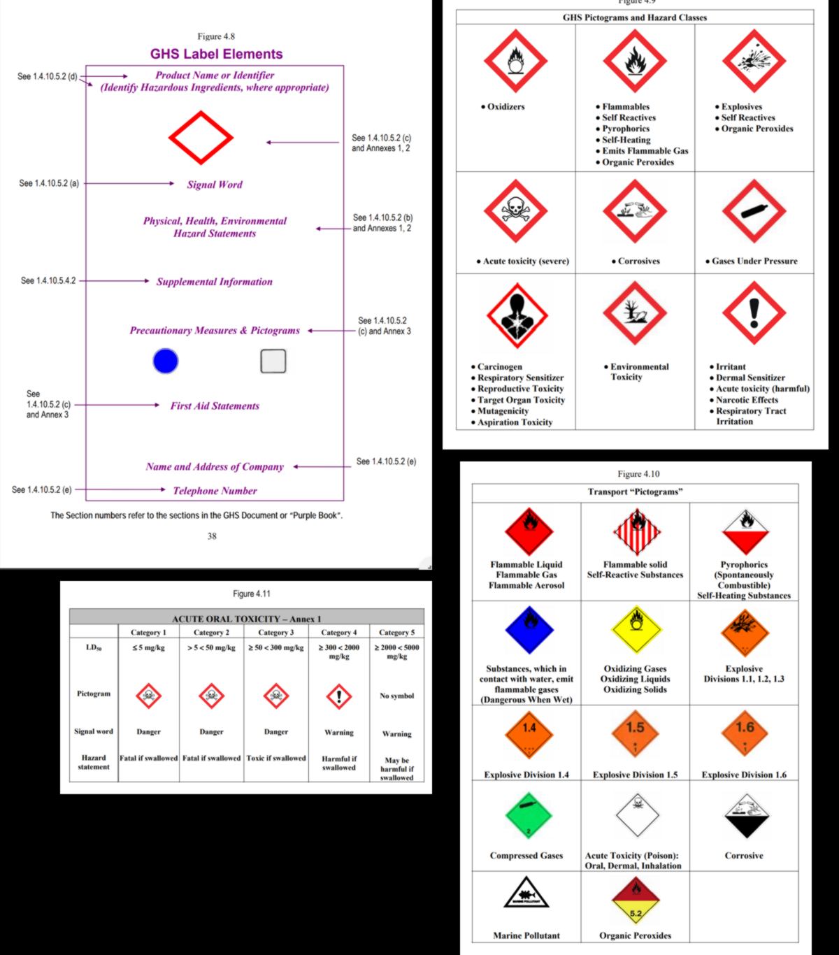
The most critical part to understand seems to be the Hazard identification. It also happens to be the most confusing. The hazards listed are drawn from a long list of potential hazards divided by health, physical hazards, and hazards not otherwise classified. The GHS system is quite straightforward : a lower number means a higher risk, while a higher number means a decreasing, but still present risk. For example :
The guide to read SDS images is particularly useful :
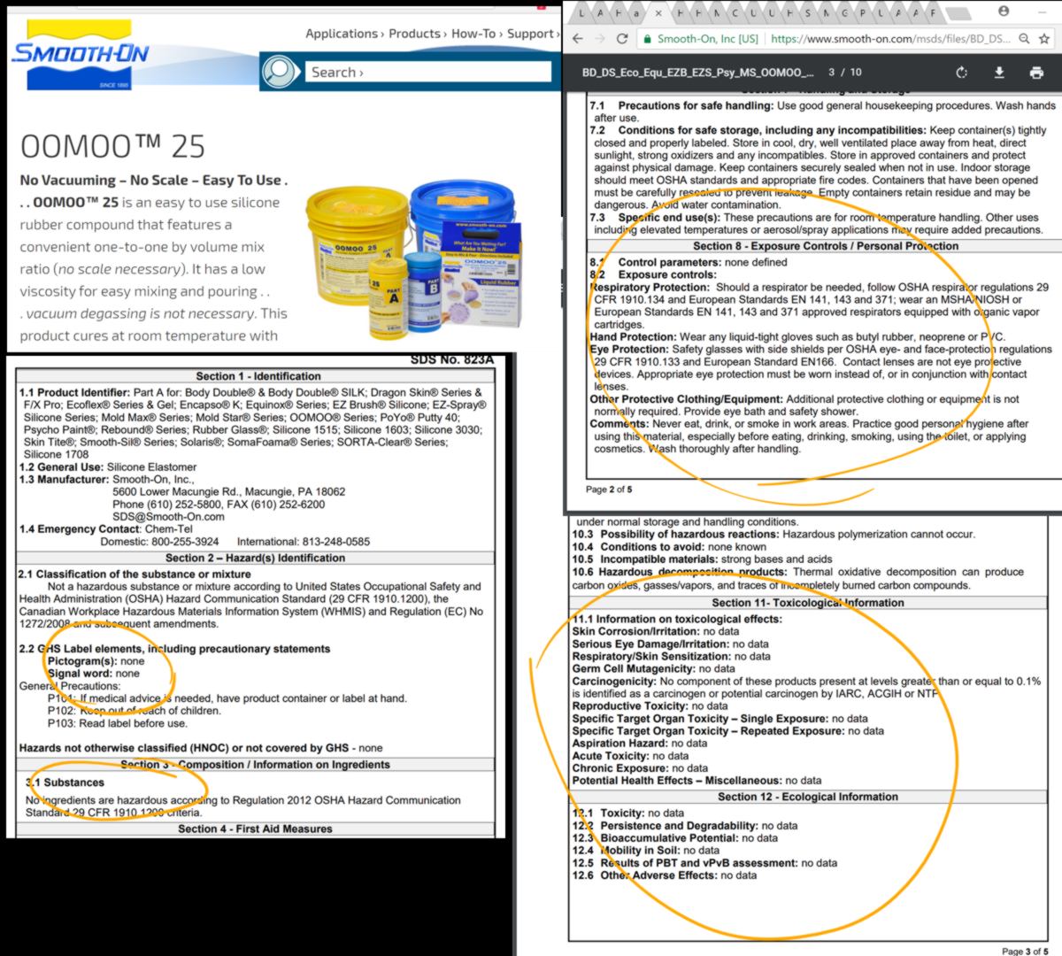
With this in mind, I look for the safety data sheet of the FormSil 25, a product we use here. I however cannot find it here and the lab is closed today, so I select another product, the Oomoo 25 to get used to this decifering exercise. Sadly (or luckily?) this product is very safe to use : no specific warning, it is not corrosive, the only recommended protective equipments are gloves and glasses :
I move on and look for epoxy resin, something that is commonly used to create watertight surfaces on boats. It is a little more delicate to handle this time :
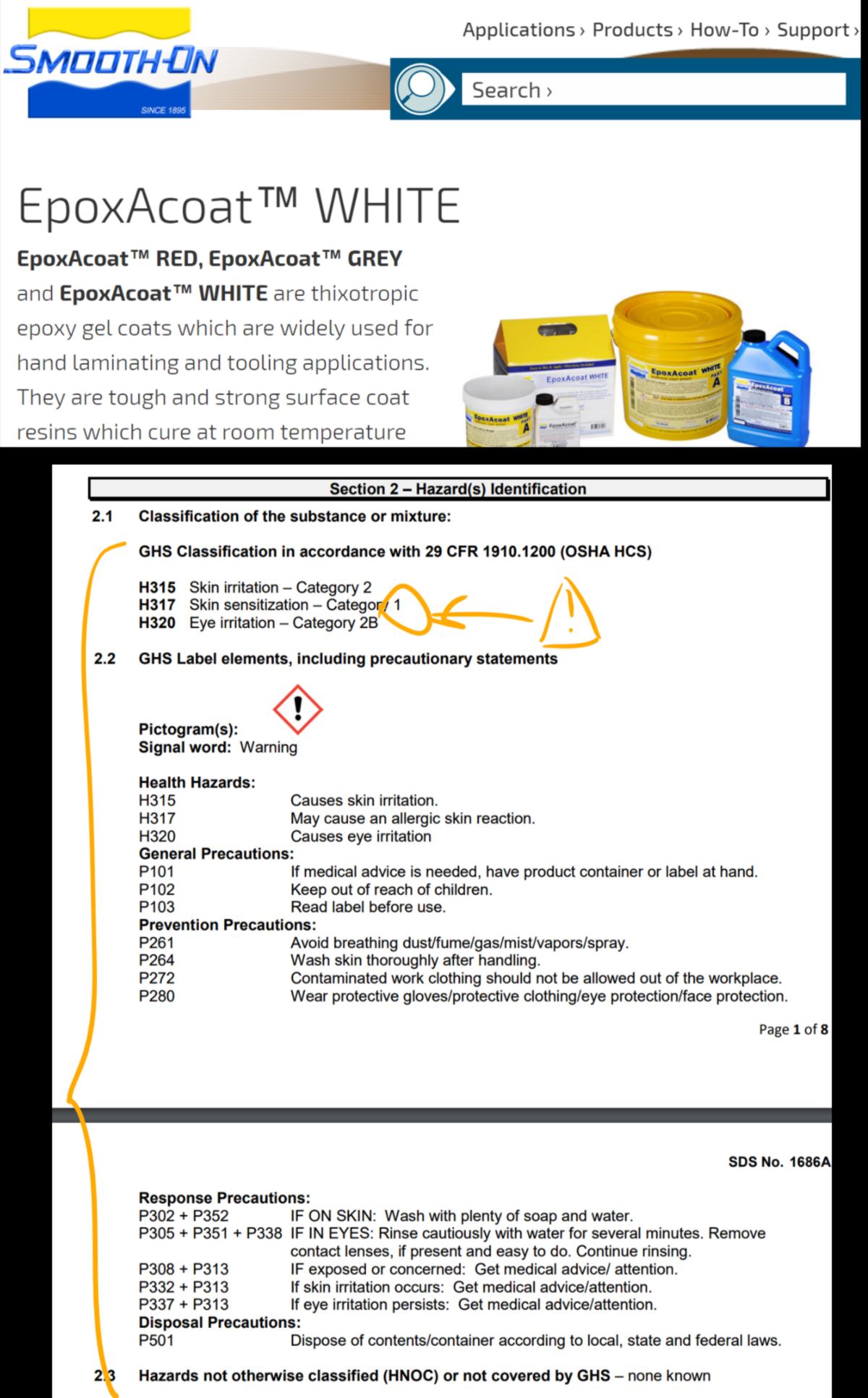
The skin sentitization factor is particularly bad, which means a user might develop very bad reaction to the product overtime. For this product I would wear long sleeves on top of the usual glasses/gloves equipment. A mask would also be recommended if used inside.
Let's have a look at a beautiful, but particularly harzardous one :
Overall, although the level of protection changes, it is always good to get started with the basic long-sleeves/gloves/eye protection/mask, and adapt the equipment and location of use according to the product used.
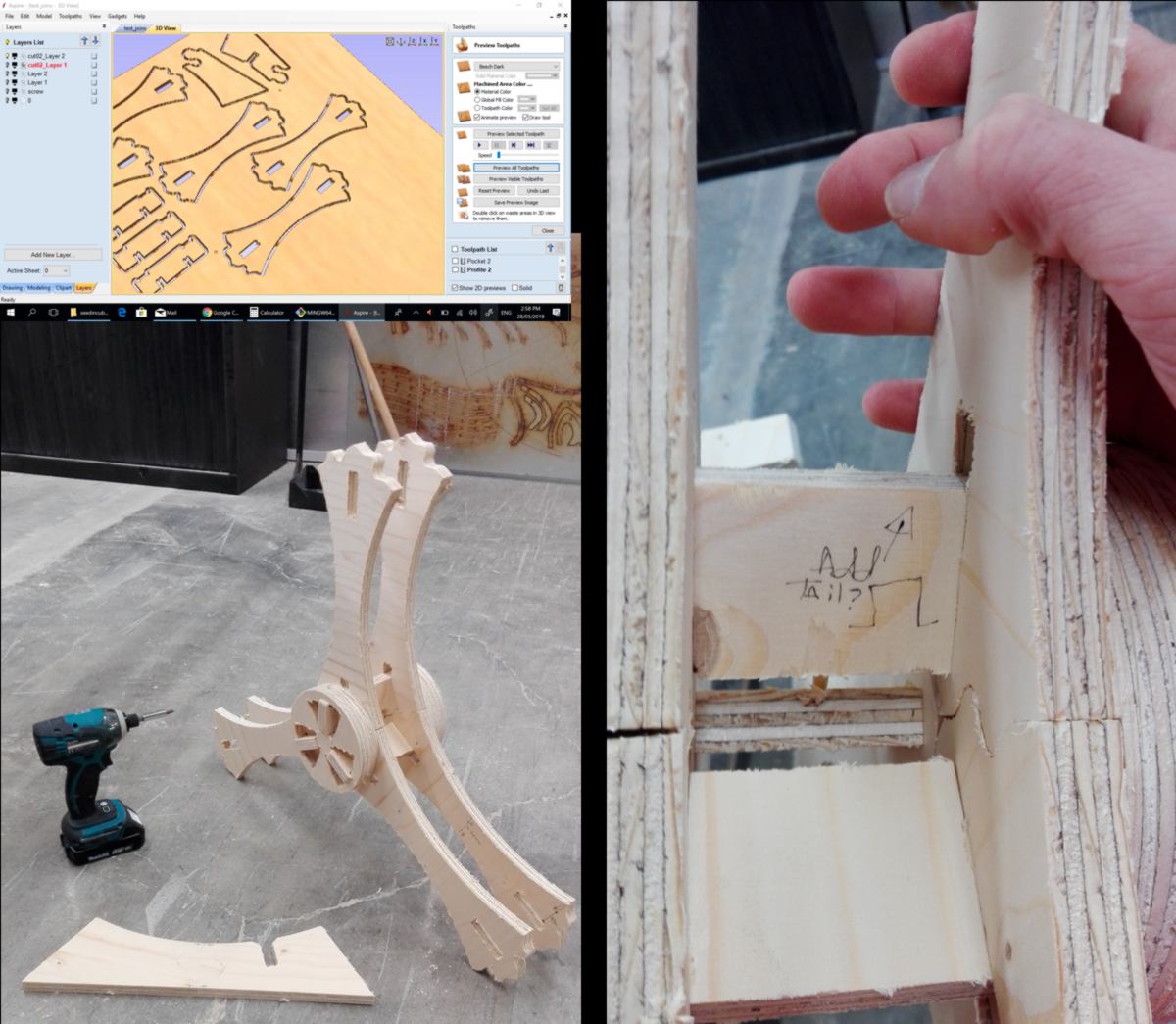
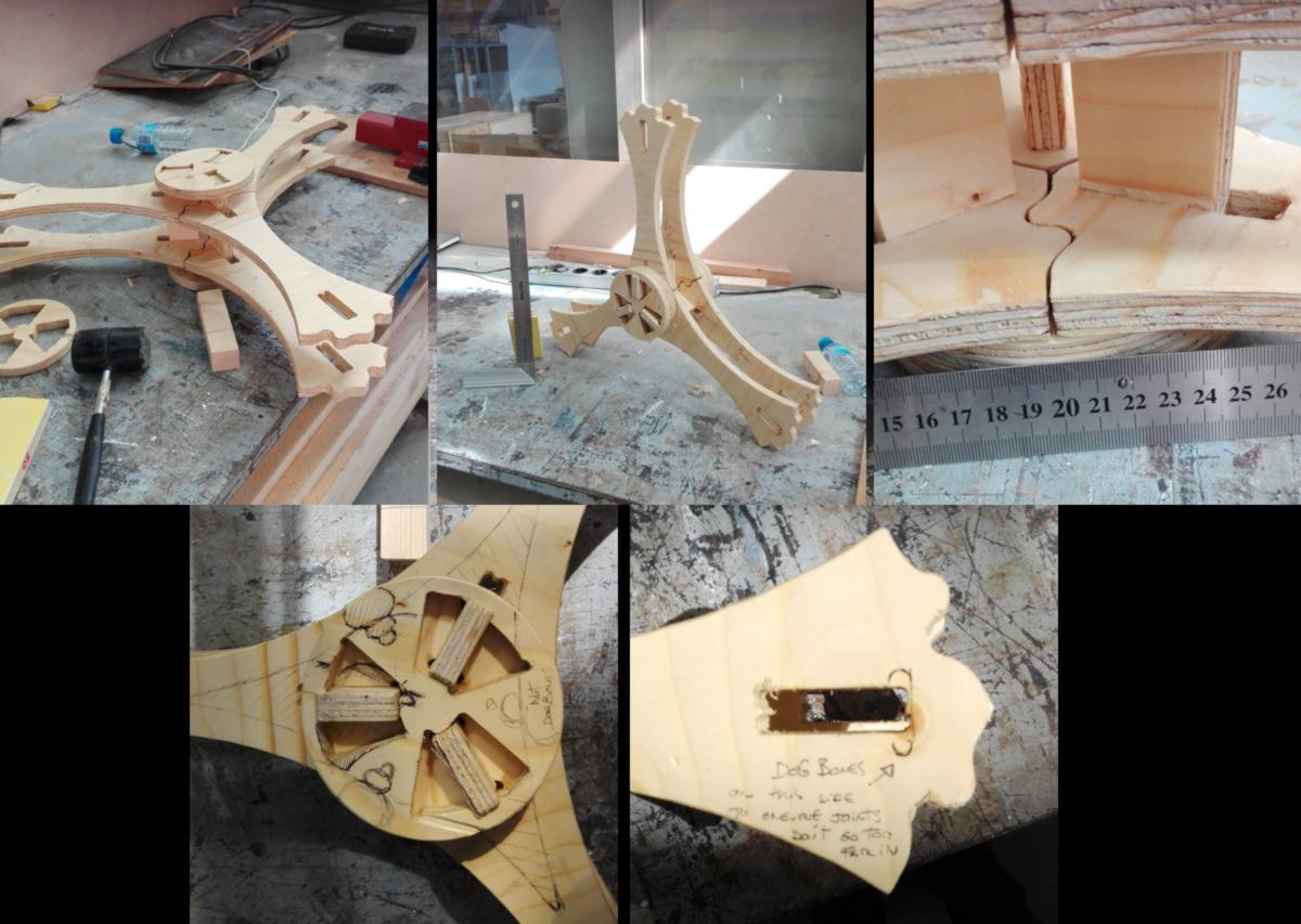
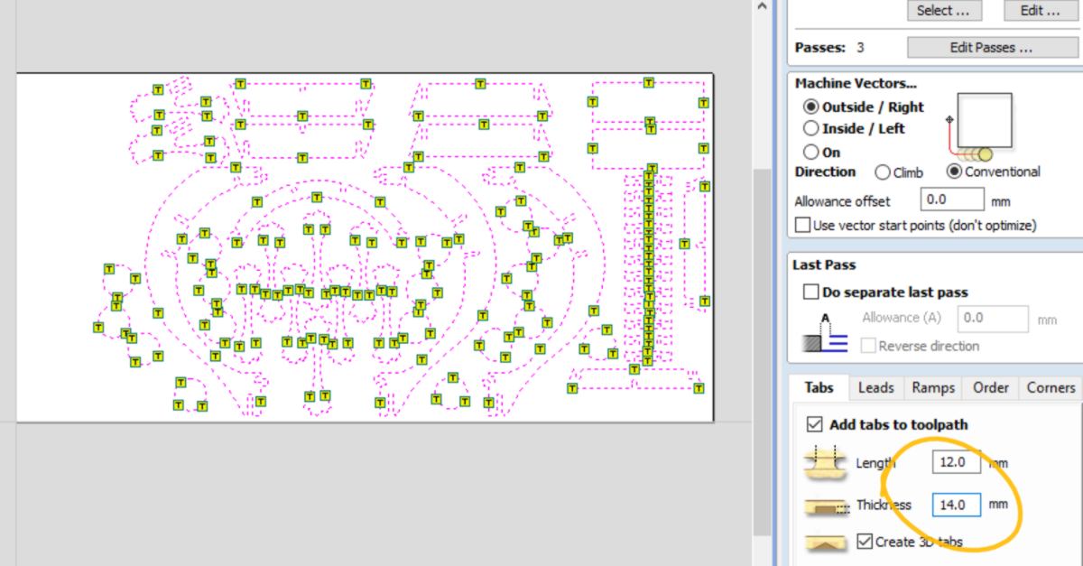
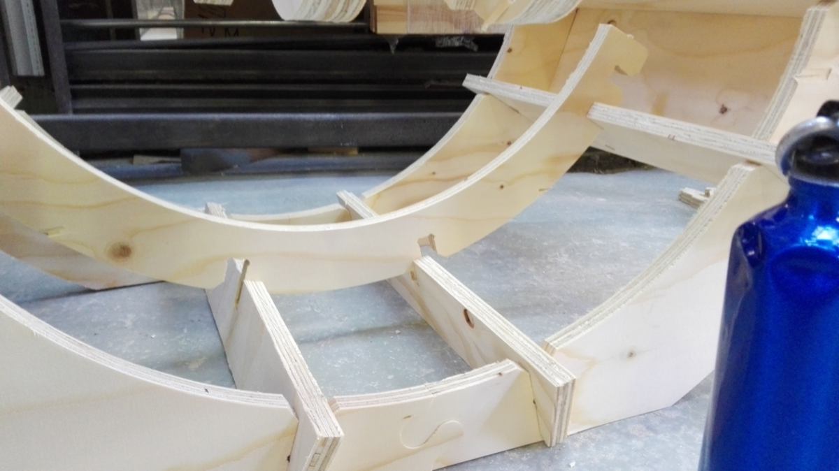
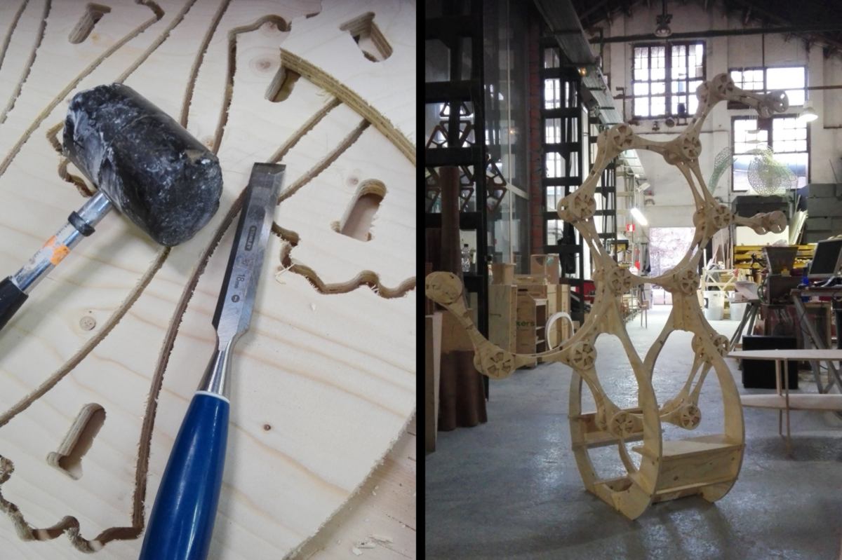
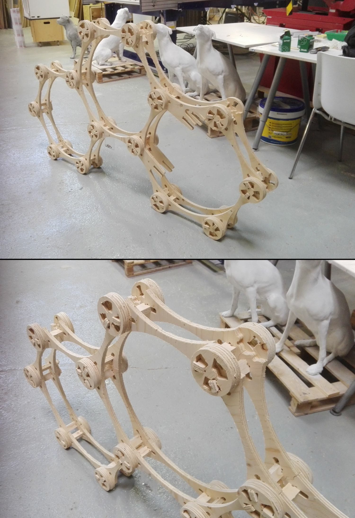
04.04.18 /It is my last day of CNC cutting for the " make something big" project. I prepare the -planned as - final version of my cnc cutting assignment. I delete all dogbones from the last version, makes adjustments on the main, bone-looking structure, making it thiner. This has an impact on the size of the circular joins, the inner frame and the base that the parametric design mostly take into account. I also add a tolerance so the wriggle shaped-end of each "bone" fits better. I finally add a tolerance on the spinning join so that it fully spins when locking the whole structure into place.
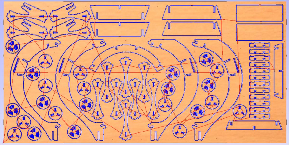
Then I add the dogbones again, modifying the location at times to make them invisible, export each shape, and nest it, keeping the distances validated during the first test :
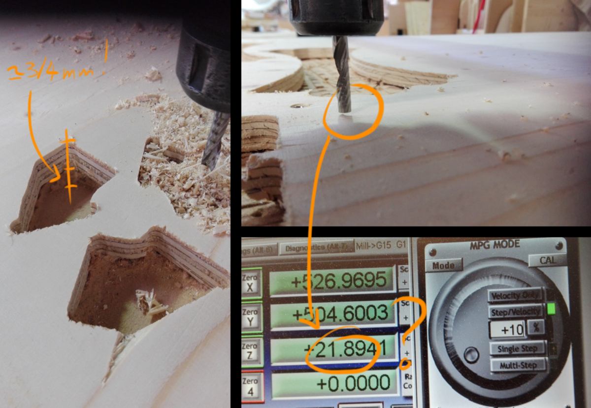
I then head to the Precix CNC machine, select a sheet that has the same thickness as the previous one (by 0.05mm), set up origin on x,y and z axis using the L-plate, drill and screw the board, and begin the cut. The pocketing goes well, but when the profiling begins, my pieces start popping out regardless of the tabs. I pause the cut and have a closer look:
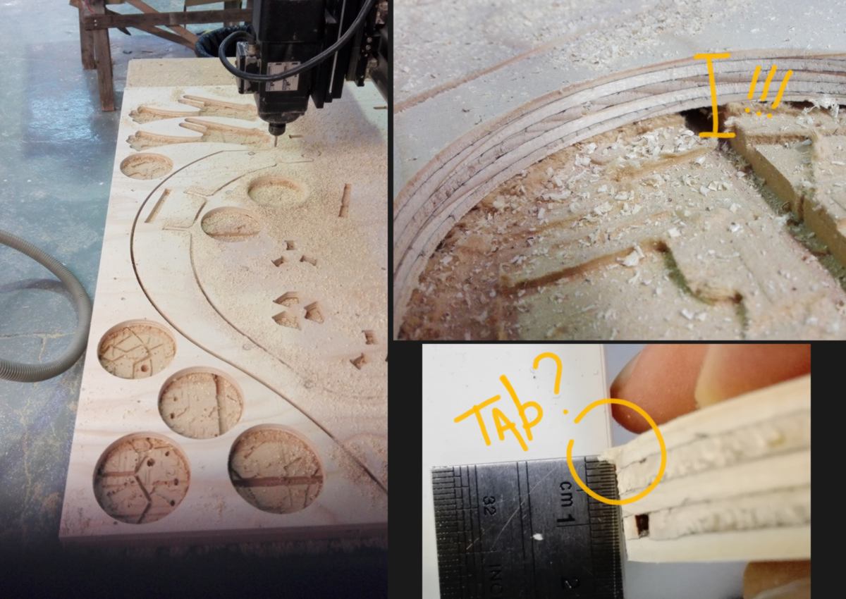
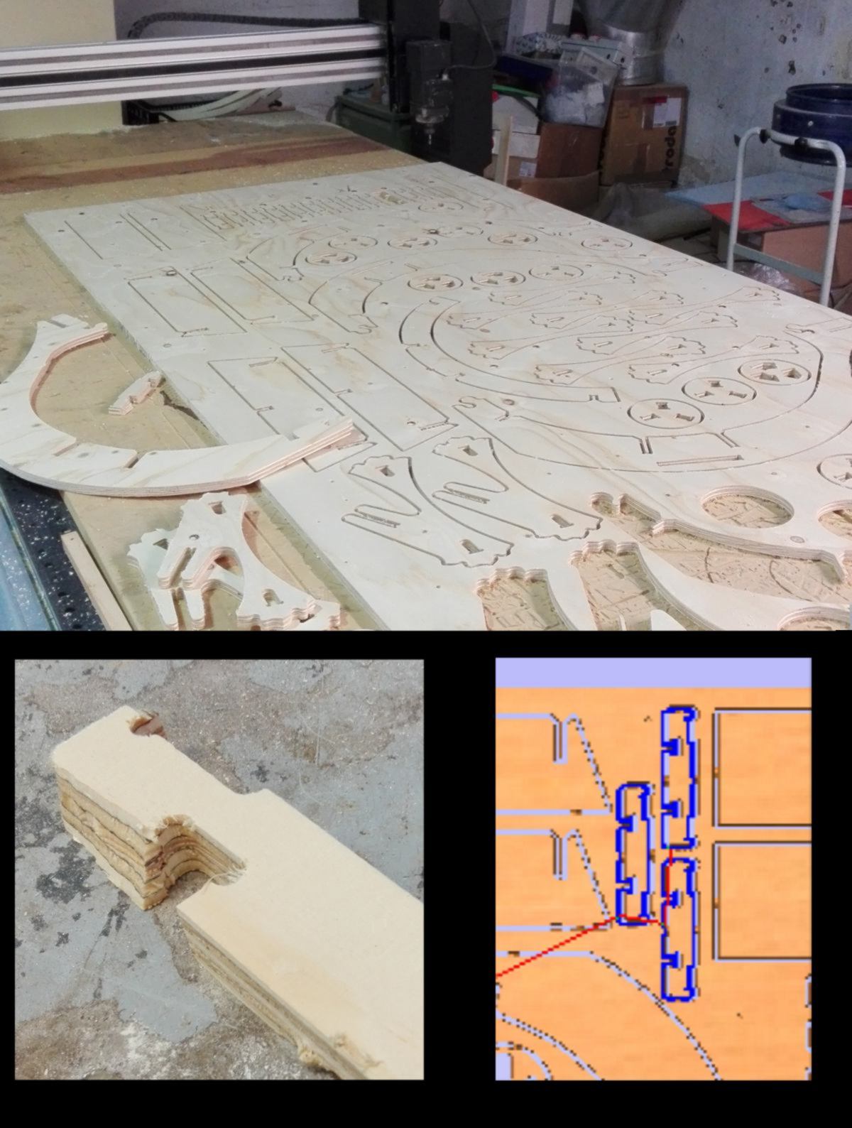
Looking for an explanation about this rather significant mistake on the z-axis, I take a few measurements and check what height the software shows where the end mill is about to touch the stock :
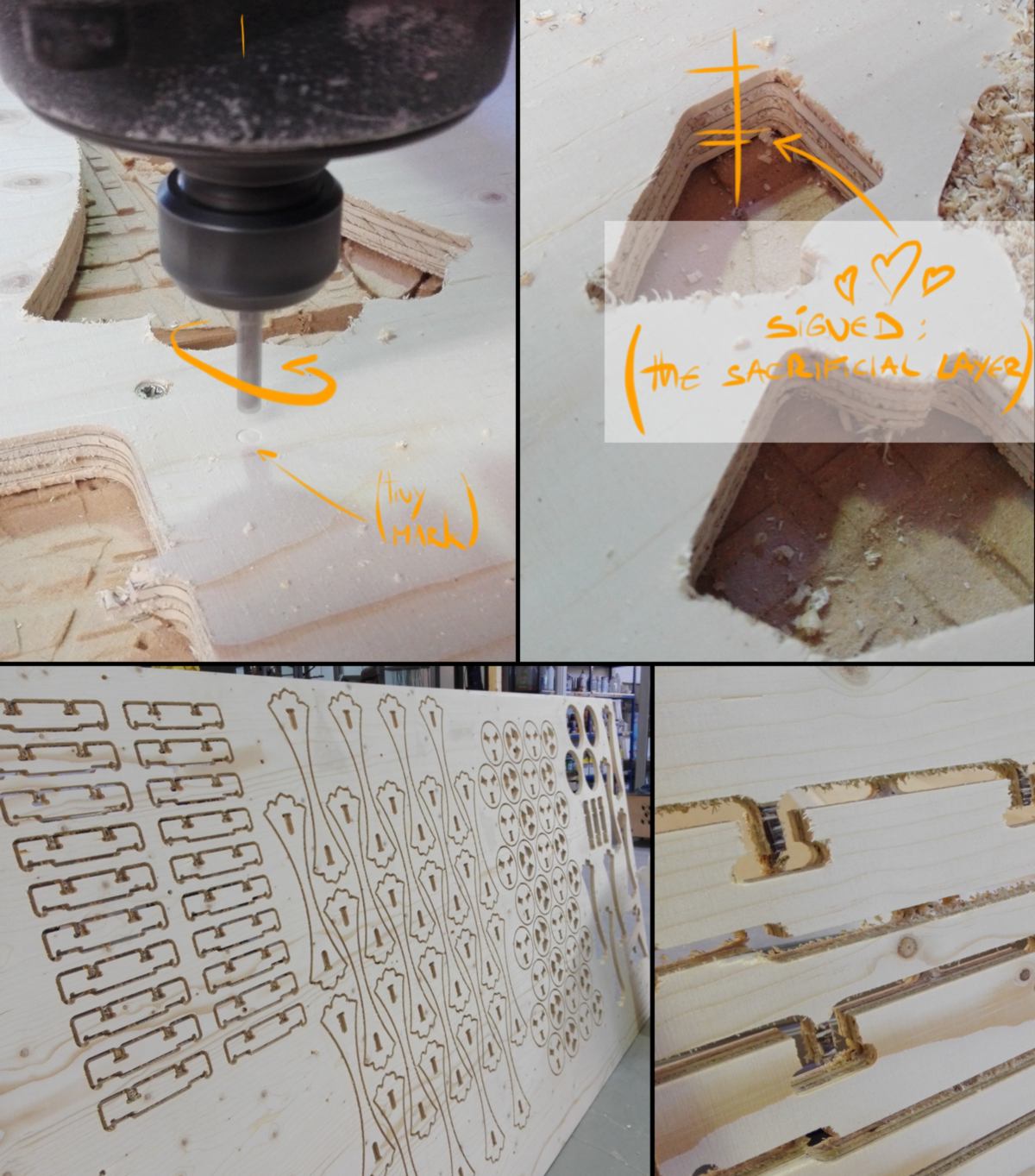
My explanation is that the sacrificial layer is in such bad condition that, when using the L-plate to set up the origin on the z-axis, the whole area on which it was resting was in a gap 4mm lower than the highest points.
This has many repercussions, one of the most concerning it that during each first pass, the 6mm end mill cuts 6+4 = 10mm of material, putting greater lateral forces on it. The noise generated was quite intense and I dropped the velocity of the CNC by 20 percent to compensate for it.
The bright side of it is that, although it is not recommended, I am now aware that it is possible to cut a 15 mm sheet of plywood in two passes with a 6mm end mill!
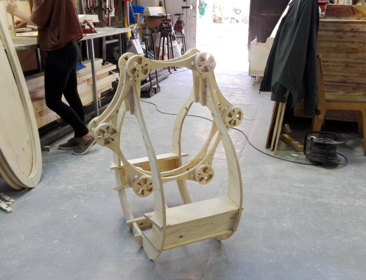
The process to finalise this design was very insightful, but also very time-consuming and it has kept me away from my final project. Now we are half way through the fabacademy, I wish to focus on an educational tool for the green lab. I might or might not recycle this design to make something else, such as a shelf.
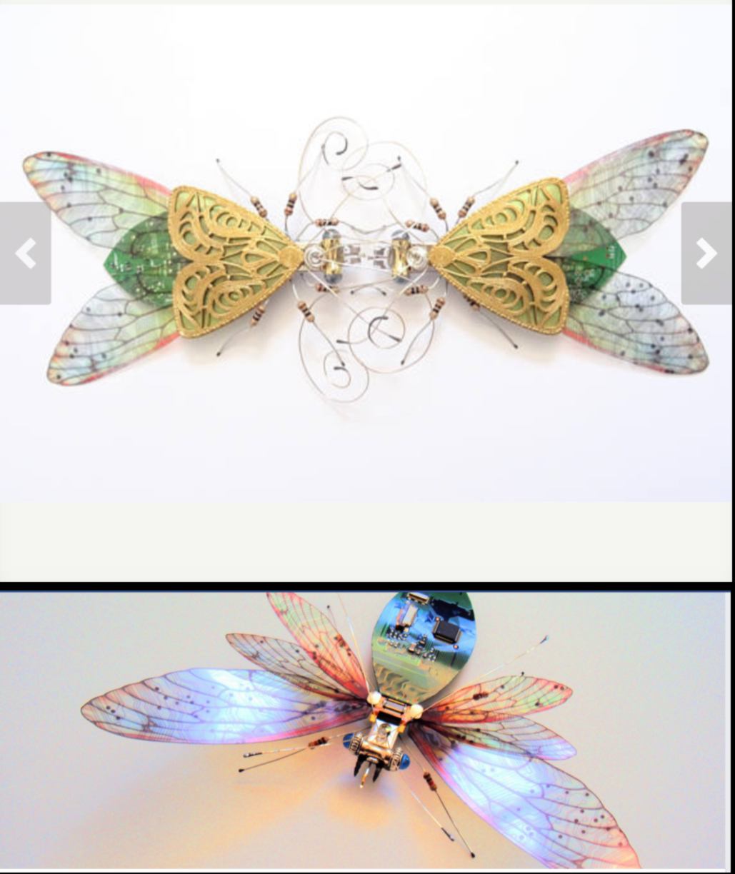
Carrying on with the design of the website for Fab Lab Auckland, and looking for a design that will represent the focus of the lab, I discover a fantastic artist who have recycled pcb and other e-waste, turning them into gorgeous sculptures :
05.04.18 /This is the final day of the modling and casting week. After a week drying, my silicone mold is ready. Today I will make a cast with a quick drying material.
The cast shows no bubbles on the surface and has perfectly taken the shape of the mold. The steps were resolution was lost was the scanning and the milling. If I had to do it again, and would only need one copy of it, I would attempt to make the mold directly on the bark itself for better definition.
In the meantime I follow the development of the mold for the dog that Ingi has been working on for almost two weeks. After milling and assembling the shapes out of foam, he created an envelope for the silicone mold. He does that in order to save on the amount of silicone used.
To leave enough space for the silicone to be poured, he first covers the whole foam with a layer of adobe, then cast the envelope. Then he gets rid of the adobe layer, and uses 2cm-long steel bits pinned into the foam to hold the dog shape at the centre of the envelope. He then pours the silicone and leave it to dry. You can see below the first silicone mold being collected.
Quick update on the website : I add a interactive map for future visitors of the lab. They will be able to immediately get directions to visit.

I had all intentions to completely set aside the aquaponic project to focus on the educational one. However yesterday, I notice that at the end of the month, there is a deadline for a waste minimisation fund, the same one as the one I applied and got some funding from. I think that if the design and a website is set up before that, we could ask for an expansion of the budget, therefore making a better design.
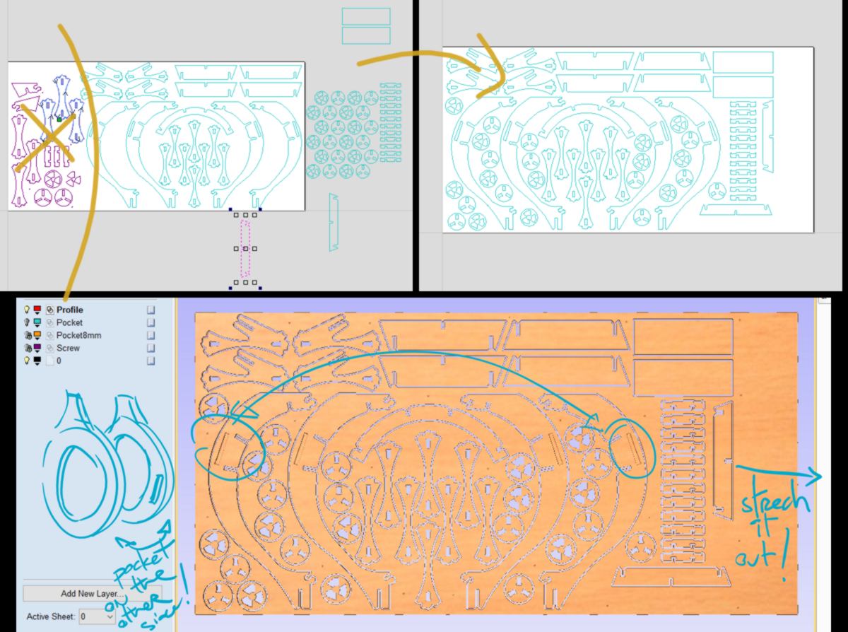
therefore today, in order to have good visuals for the website, I expand the initial shape I made yesterday. First though, I manually fix the sheet that could not be assembled :
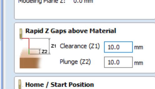
Then, using my test sheet, I nest all pieces required for the extension. It is compact and fits well. I increase the number of tabs to ensure no small pieces will pop out, which makes the cut stress-free. I also set up the tabs so as to create a web which will ensure the resistance of the sheet during the cut. Finally, I raise the "rapid Z gap above material" by the width of the stock + 2mm, so that, in case a piece still pops out, it is unlikely to be hit by the end mill while travelling.
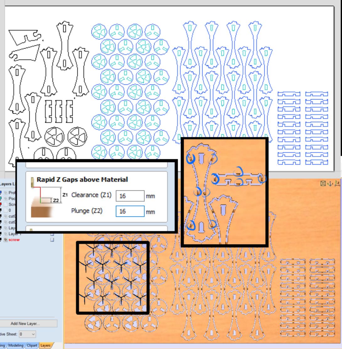
This time, I set up the height of the Z axis on the stock rather than the sacrifical layer. This way I should not dig into it as much. But to my surprise...
Discussing it with Ingi, he mentions that sometimes, in the process of restarting the Precix in order to reset, then switch on the spindle, the z-axis is modified somehow. To set the x axis correctly, I switch the spindle on and move it down until I am in contact with the stock, then set up the thickness of my stock.
20.06.18 / LAST MINUTE ADDITION I add below the links for products I used at the lab : the FormSil 25 and the Ferris Wax.
You can find the webpage about the Forsil 25 here . The mixing ratio for this product is 100 (part A) for 5 (part B), with a working time of 3 hours and a curing time of 14 hours.
You can find the webpage of the Ferris Wax here . We use blocks of roughly 150x100x35 mm of Blue wax (the equivalent of a One Pound Packages: 5-3/4" x 3-1/2" x 1-1/2"). I insist on the roughly since the wax is constantly recycled, and recycled blocks do not precisely match this dimension.
The blue wax has a hardness rating of 52 and an excellent felxibility, which makes it a poor material for high-speed CNC but is absolutely fine to use with our Precision milling machine at slow speed.
Going through the safety data sheet, I looked for the melting point, and found the following: " Melting Point : No data available". However I found that for other machinable wax a temperature of 290 degrees F ( around 143 degree C) is enough to melt the wax.