Attending the Fab Academy in Barcelona, I document each week of intense learning as I come across new digital fabrication techniques.
This documentation is as much a report of what I do as a reflection on why I do so, and will hopefully guide me back to Oceania to spread and make good use of the knowledge gathered along the path.
21.04.18 / With no access to the electronics lab over the weekend, I move on to the next week. There are many options for application programming, and I have been recommended Javascript for online application. However before getting into it, I want to read a bit more about other accessible languages such as processing and python.
I find a tutorial about getting Processing and an Arduino to communicate with each other. I also learn a great deal about serial communication. Some lessons learned :
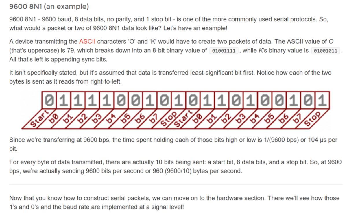
The Arduino to processing example is simple at first but get relatively complex for a newbie. In my case, I wish to write on the EEPROM of the microcontroller. I go through a Sparkfun tutorial which provides background information to get a better grasp on what happens at hardware level.
On ITtinies, EEPROM can take up to 100,000 writes before failing. In my case, updating user access every hour of the day, everyday, the EEPROM would last 11 and a half years. Sounds like it will do the job, and could even be re-written everyhalf hour during the day, and not at all at night.
In my case, I could try to write on the EEPROM of my arduino or PCB so the RFID card can grant/refuse access. I do not have access to my electronic though. On top of that, this is just half of this week assignment. In the other one, I need to set an app which can generate the file that will then be uploaded onto the EEPROM.
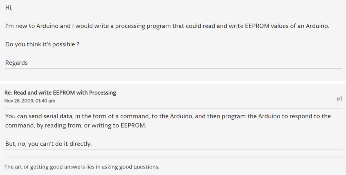
Can processing directly write something on a microcontroller's EEPROM?
Mmmmh. What about Javascript?
I quote : "ArduGate is a web gateway for Arduino. It makes interactions between in-browser JavaScript and Arduino possible." exciting. So what is Ardugate about? Oh, and hold on, what is noduino about? And Firebase? STATE API? Johnny-Five?
22.04.18 / So what is Javascript? A good intro about it can be found on MDN web doc website. I listen to bits of this week lecture to refresh my memory.
Out of all ooptions available, P5 get my attention :

""p5.js is a JavaScript library that starts with the original goal of Processing, to make coding accessible for artists, designers, educators, and beginners, and reinterprets this for today's web."
P5 has numerous libraries including a serial library , enabling connection with any devices using serial connection. I go through a very quick welcome tutorial:

Before I get deep into coding, I would like to prototype my future app using a visual flow logic software. I look at all of the ones described during the lecture, looking for something that uses Javascript and in which I can create my own node. I happen to study with Eve, looking for switching an LED on and off from her phone and via a tutorial, we find evothings. This is a platform to run apps written in JavaScript straight on your phone. Although that is useful, It is not a visual coding system.
After a quick overview, p5.js really seems to be user-friendly and I could sketch what I want without a visual coding system. However there are no tutorials on the website. It seems like the developpers expect new users to know Processing from the start. Therefore the path to get to p5.js goes through Processing. I download and install the API. Dan is teaching us the basics :

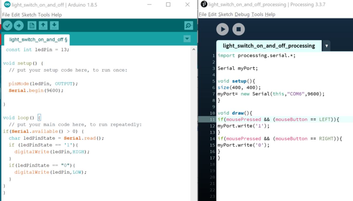
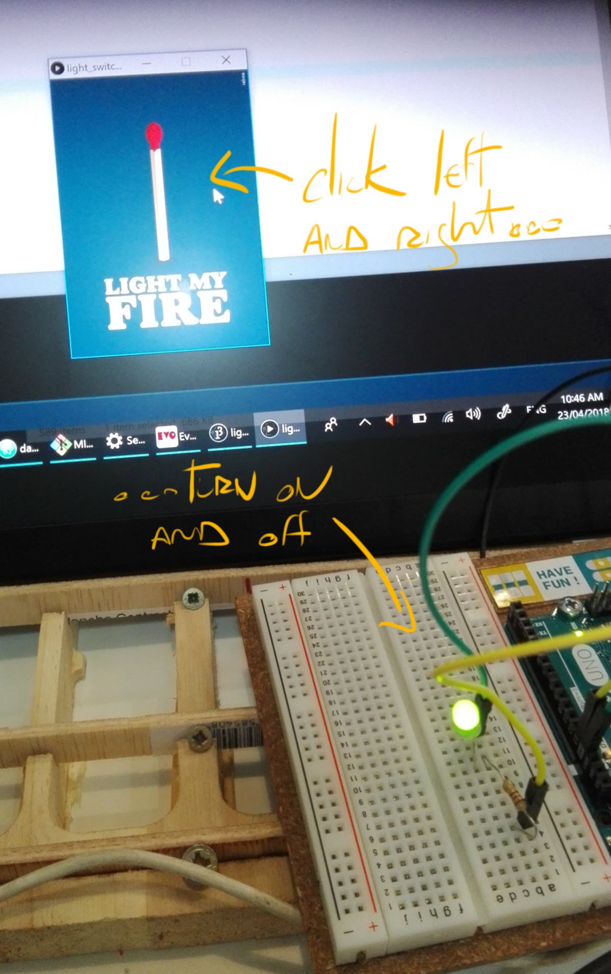
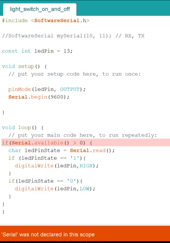
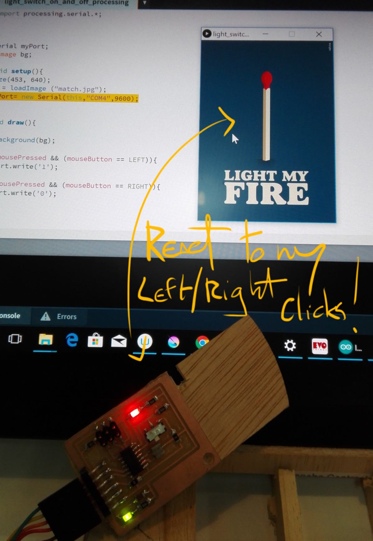
As a first approach, we are going to do a simple output device using processing as an app to switch a light on and off. We use a tutorial and write a bit of code in both the Arduino Environment and in the Processing Environment :
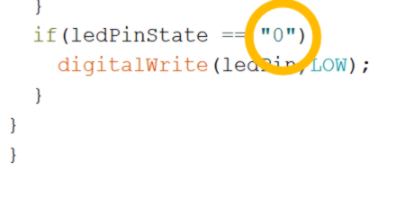
I test out this code on an arduino. The LEDs stays on and does not react to the right click. I figure out that it is because of an syntax error : I used -""- instead of -''- :
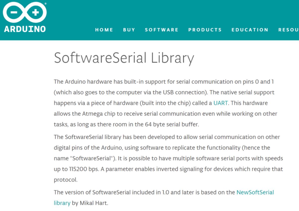
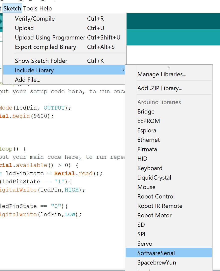
My final goal is to load this code on an ATtiny, therefore I need to correct one extra thing. The default Serial library in the Arduino IDE does not function with a AT microcontroller. I look for another replacement :
I add this library to my code and attempt to compile for an ATtiny. I do get an error message :
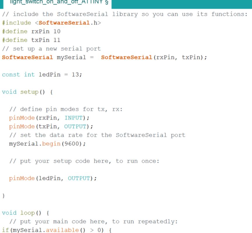
I rewrite my code more accurately to fit the new library :
By the way dear reader, I lied to you for the last two/three steps. The sun has gone down, then up and now, today is actually the ...
23.04.18 / I use my hello board to test this bit of code out. It has an LED, so it fits the requirements.
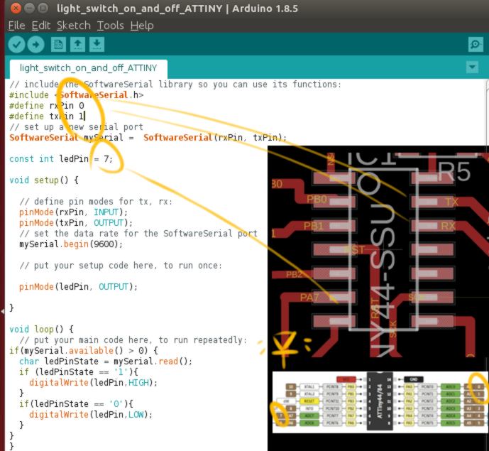
I launch ARDUINO IDE in Admin mode using the command line, then make a few adjustment to my code. First I need to adjust the pin used by the SoftwareSerial so that they match the ones used on myATtiny44. Secondly I need to modify the pin number used by the LED on my board :
The result is equally pleasing :
That is a good start for interface/serial connection. I go back to the electronics lab to stuff the board I milled last week. A few comments about the process itself :
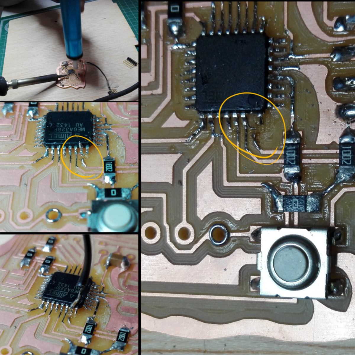
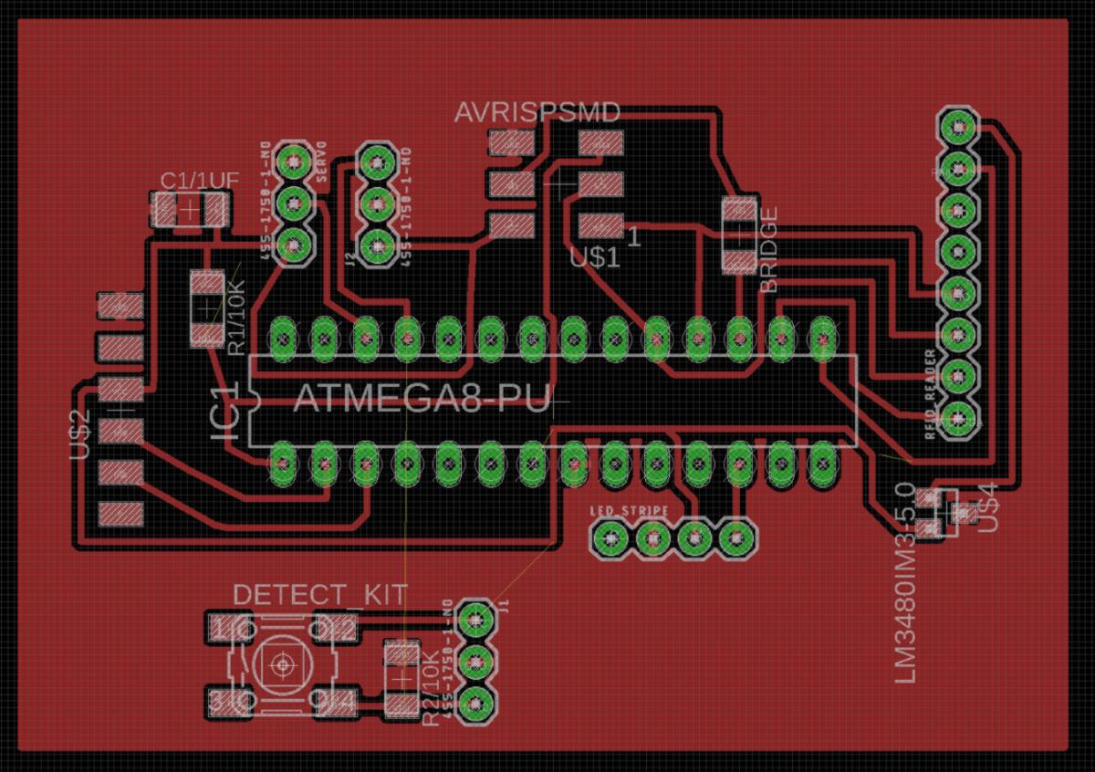
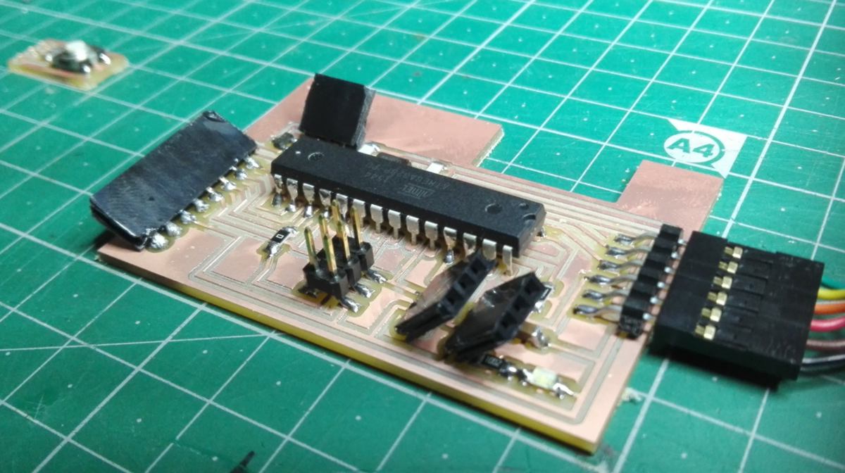
- As you can see below I have so many bridges on this PCB I ended up developing a method to fast-solder these tiny 0 ohm resistances. I put a tiny bit of solder on one side, then put the resistance flat right next to it, barely in contact with the solder. When I re-heat the solder, the resistance slides into it, putting itself in the right position. Convenient.
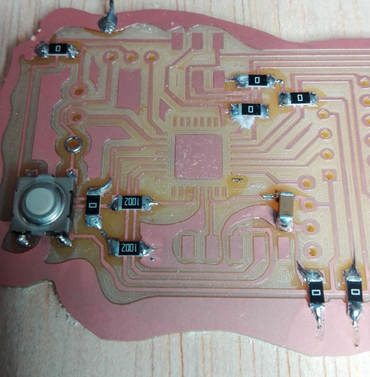
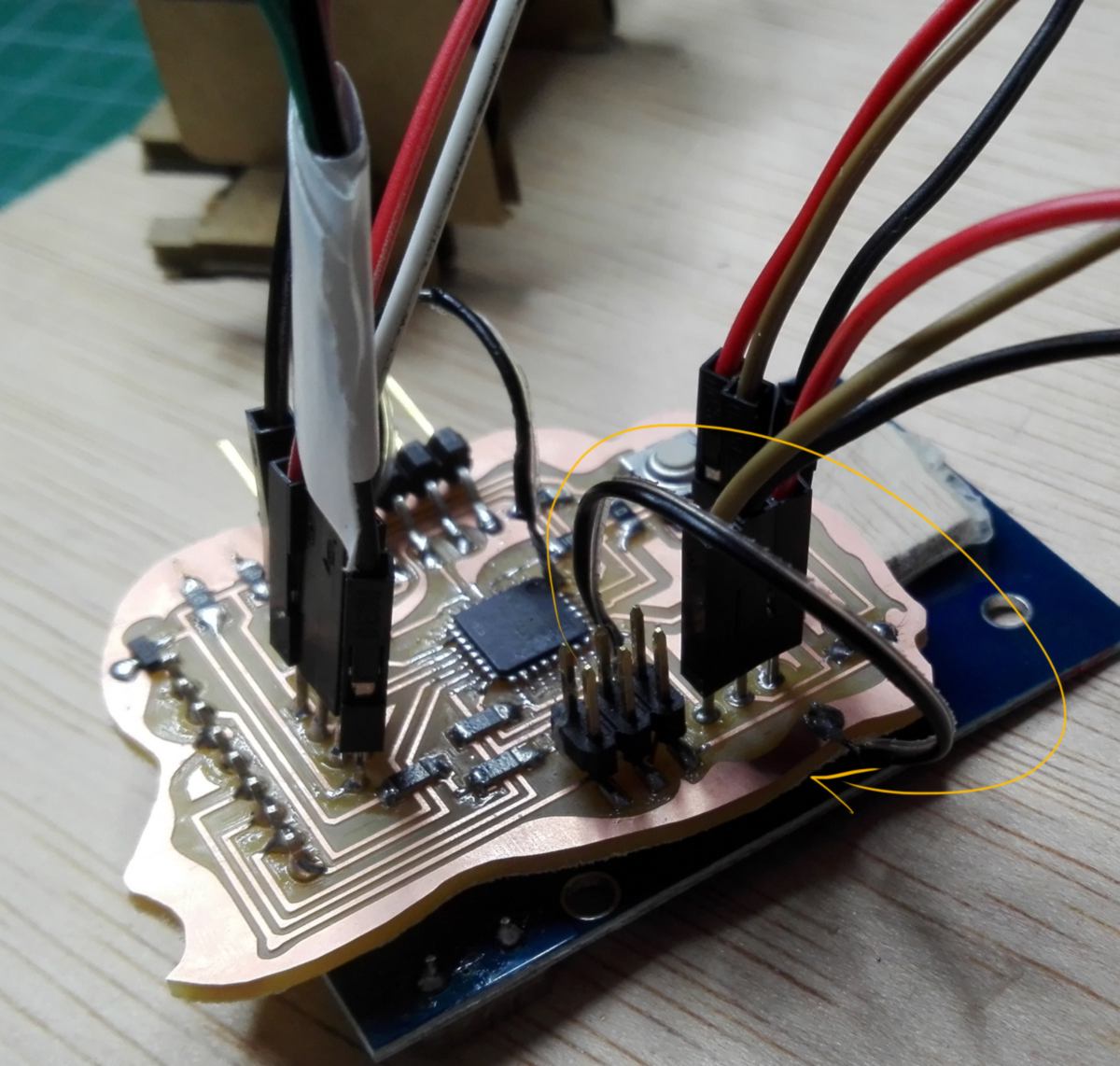
- Being all arty when designing a PCB is lovely. However clearing out a ground connection with a blade in the cleaning process (simply because we thought of it as a useless decoration) is less lovely. You can see below the black jumper connecting the ISP ground pin to the Ground in an elegant loop.
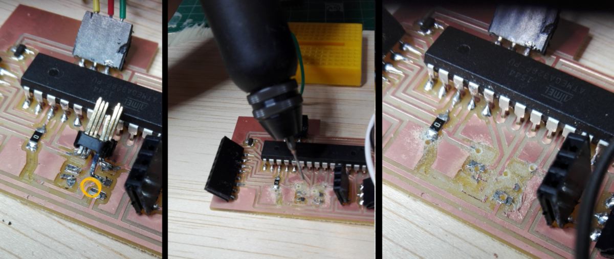
- Soldering the ATmega328 au requires a completely different approach than usual. The pins are so small it is impossible to solder them separately. In this situation I am going to use some flux in a silimar way as in this video. I will first clean the board with alcohol then position the chip and secure it with a touch of solder, apply the flux on the pins and add solder to all pins all at once.
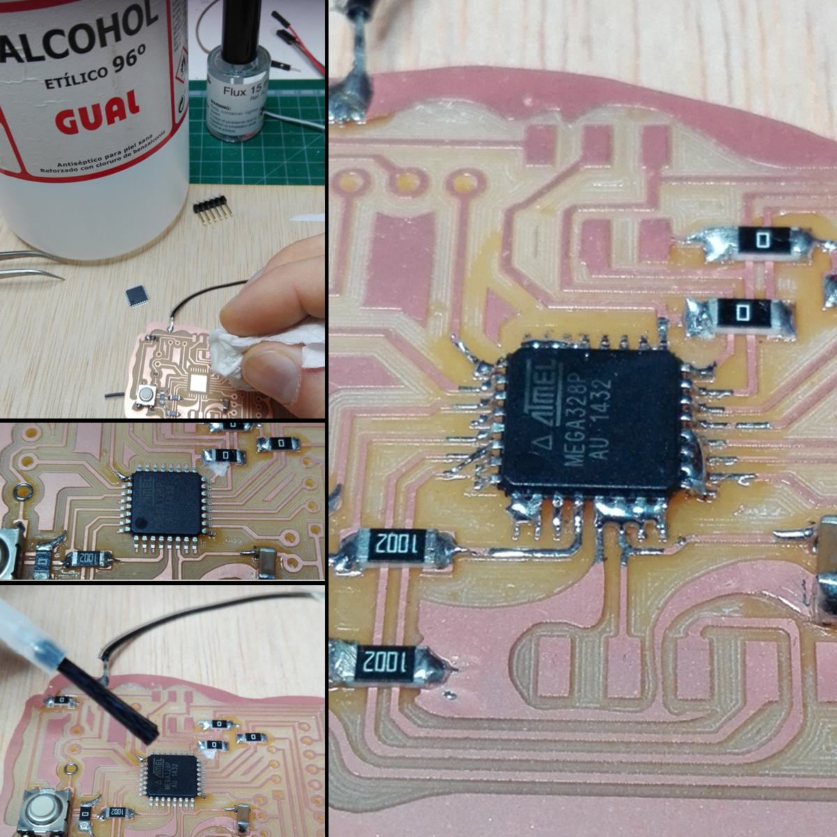
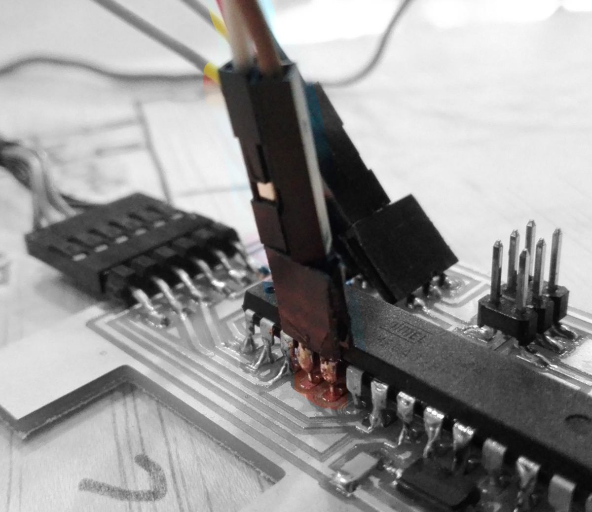
The result is precisely the opposite as the one intended : all pins are soldered with one another. With the help of a tiny pin-vacuum (?) and some soldering braid, I attempt to clean it up. In the process I damage the copper on the PCB which connects to the Rx pin. I add a jump to directly connect it to the serial, but the jumper breaks, taking the pin off the microcontroller. Ooch. In a last attempt I jump what is left of it, merging it with the (unused) pin next to it. Dodgy fix.
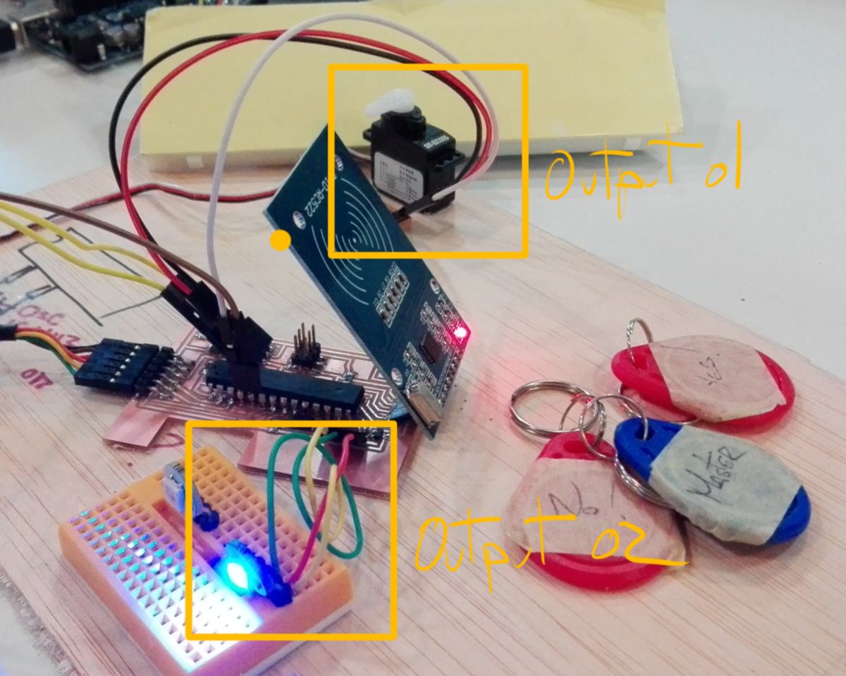
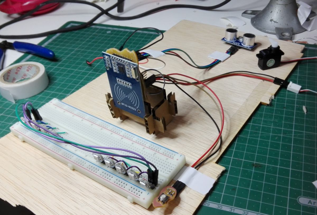
I add all other components, including the RFID reader which is located underneath the board. The idea is to have it facing up at the end, with the board facing down.
I test all connexions with the multimeter as I add components and finally attempt to bootload the PCB, which returns an unexpected error. I re-check all the basic connexion between the microcontroller and the ISP header, but it all seems in good order.
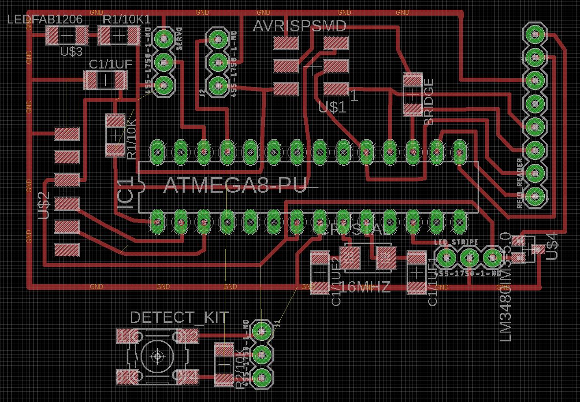
At this stage and considering the complexity of the board, I better re-do it all, using what I have learned to make it work :
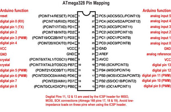
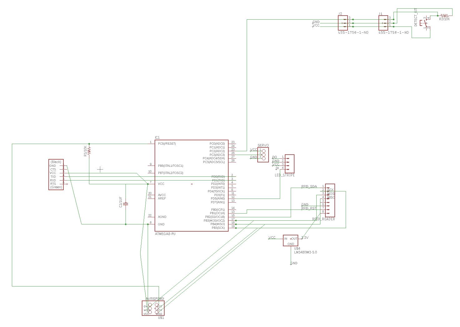
I am back into Eagle, reconnecting every single element to a schematic of the MEGA 328 P, double-checking the pin mapping between my code and the microcontroller. The fact that I can go between each pin of the microcontroller makes the routing much easier .
24.04.18 / Below is an accelerated version of the beginning of my day :
Results? Not working.
Before I attempt to debrief, I put a few pictures below to give you some context :
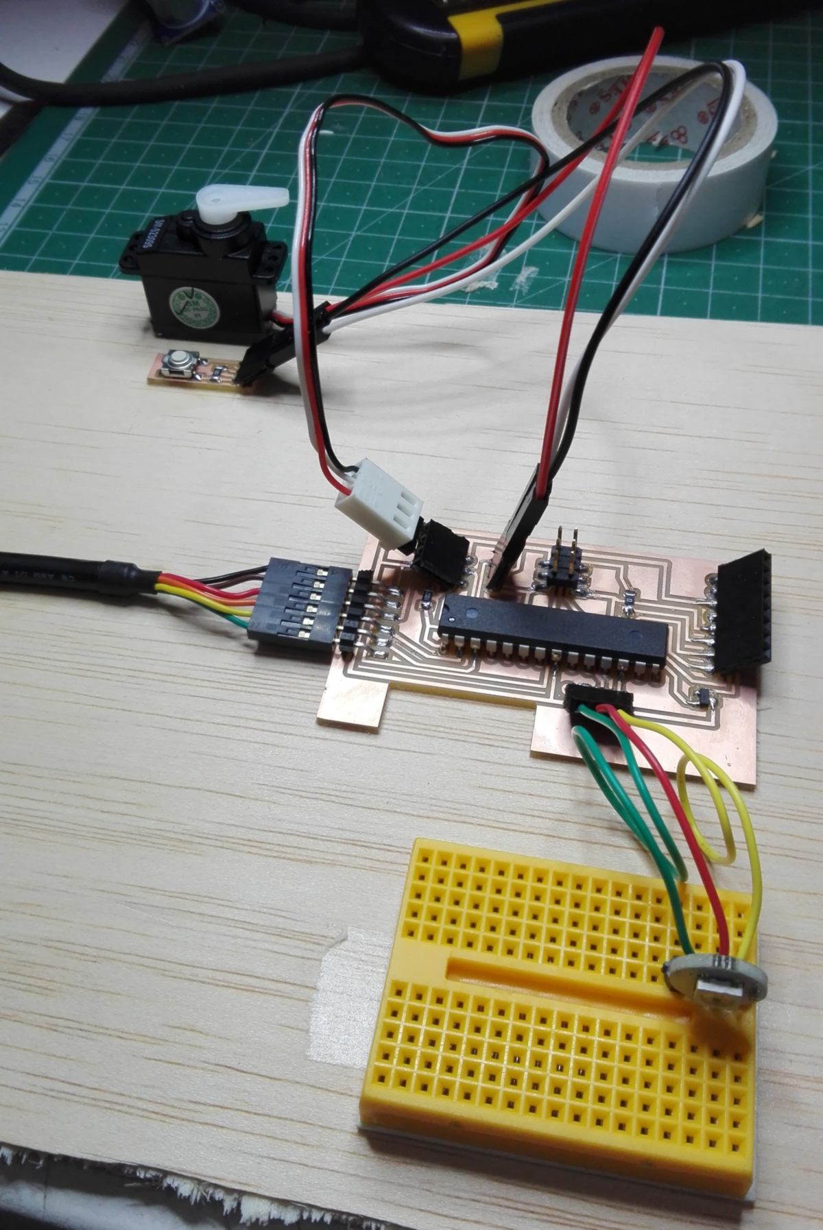
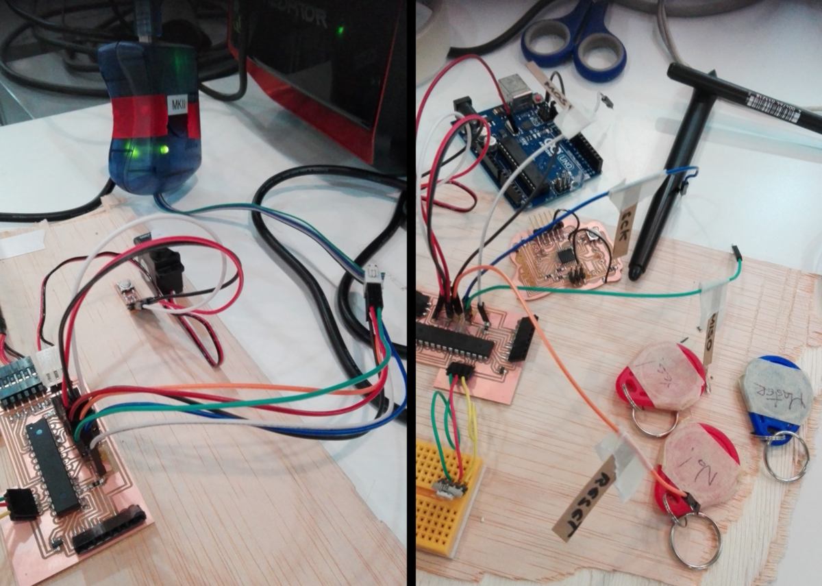
Firstly, I should have attempted to make this system on a breadboard - microcontroller included - to know how to ensure I can bootload it. My issue is that now, I cannot tell whether the issue is harddware (soldering issue, wrong pin) or software (not the correct parameters to bootload/download).
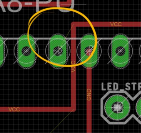
I need a fresh eye. My instructor joins me and we check my schematic, and realise I forgot to connect my pin to the VCC :
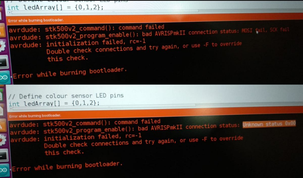
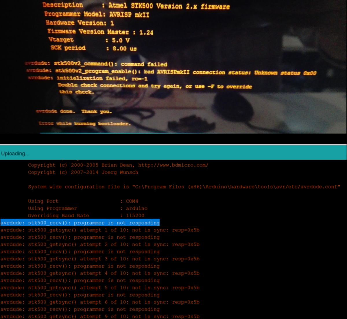
A bit of solder fixes it. I attempt to bootload it but receive another error, apparently quite common :
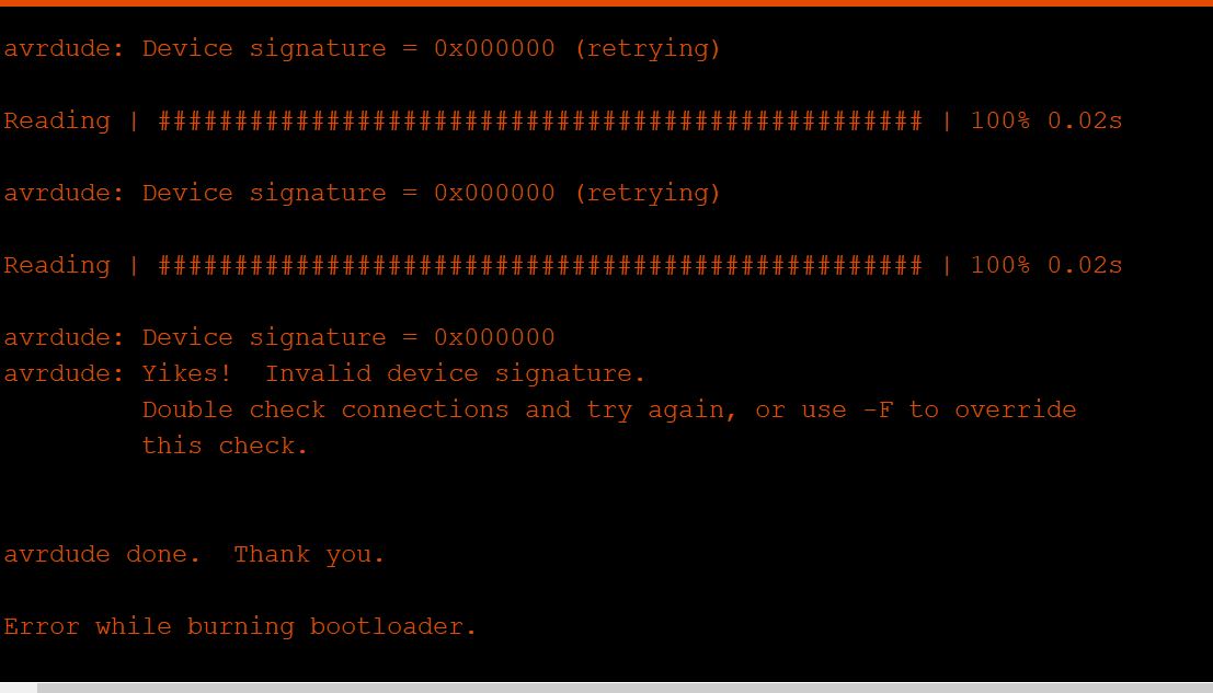
The issue with this error message is that it seems to be used when the board is disconnected. And many users have found many counter-intuitive solutions, such a trying as fast as possible to bootload until it succeed. Some others recommend to add resistances and capacitors. Some other to modify a file which seems to make it function. Some other recommends to force the execution of the code.
After reading recommendations from many forums and chatting with another instructor I am persuaded that I am missing some components on my board : 2 capacitors and an oscillator:
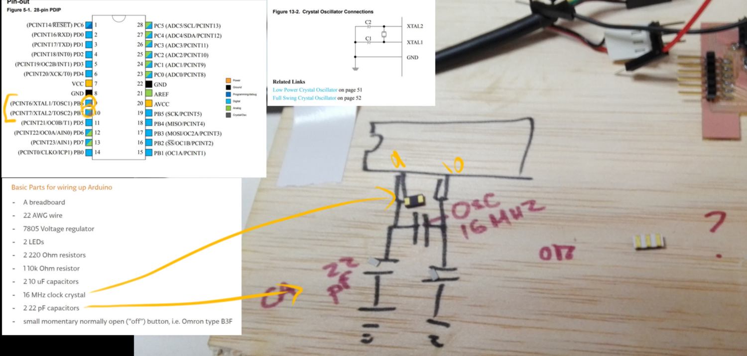
I collect all the components required and leave it for tomorrow. This means that I might have to mill my board again. I will adjust the design in a moment, but first I am going to read this webpage to ensure there is nothing else that must be added to function properly.
I end up adding a combo LED/resistance to check power, switch the output for the NeoPixels from 4 to 3 pins, and add the oscillator/couple of capacitors. I also adjust many routes to ensure they will be milled correctly, without unwanted connections.
I also wish to start cleaning up the code for this board today. I intend to write on the EEPROM using serial, so I do not need a master key, nor a RFID recording system. I can also get rid of the wiping function. I wish to clean up the code to add the serial communication later on. In this process the code size drops to 8.5MB.
I go binge watch a few episodes of our good friend Dan about p5.js, also install it on Atom and have a play with the basics.
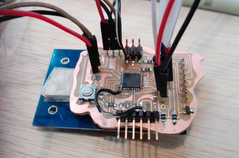
25.04.18 /Before I mill a new board I will test the new additional components by adding them to my current board with a bunch of wires :
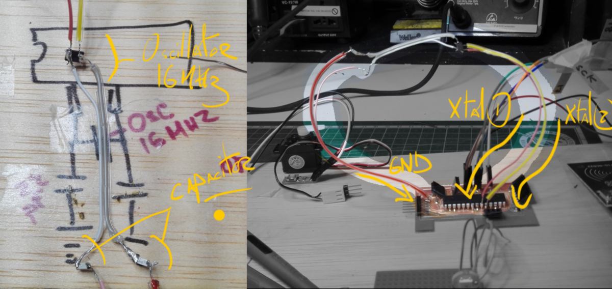
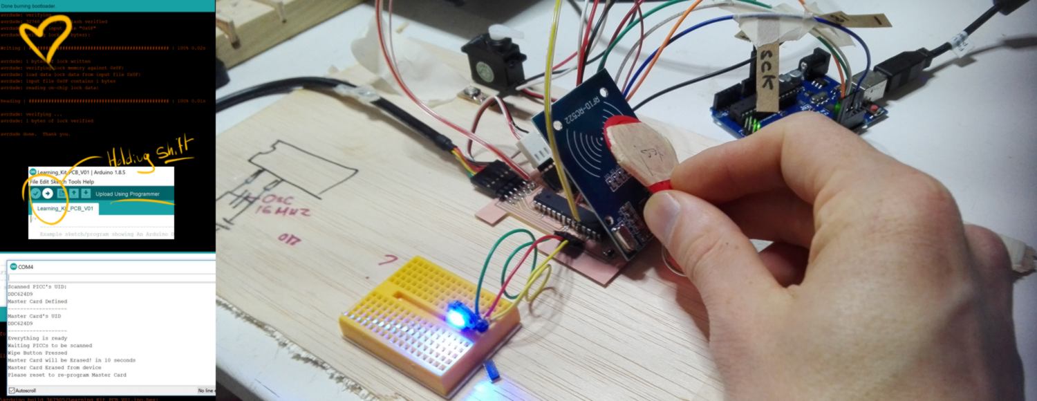
I then attempt to bootload the microchip. It works just fine. It is really good news! I load my sketch on it (using an Arduino : the trick is to put the Ardunio in "Arduino as ISP", load the Arduino ISP sketch, connect the microchip and Arduino correctly (see video/documents linked from yesterday) and when uploading the file, hold shift to upload the file to the microcontroller rather than the arduino used as a programmer.)
An unexpected added bonus comes with this setup : the serial connection works without modification. This is one step taken away from my future work.
I mill and stuff the board from yesterday. In the meantime I order a few ATMEGA328P-PU and corresponding sockets. The reason why I will stick with this microcontroller is because it it much more convenient to debug and resolder. For prototyping purpose, I might have in the future to solder new elements straight on to pins and this microcontroller makes this process much smoother. Once the prototype is perfectly functionning I might move to a smaller microcontroller.
26.04.18 /I test my board at first I bootload it and download the version 01 of the code I wrote in order to ensure all components work. The RFID reader and the Noepixels work fine. The servo and the button do not. I attempt to test them individually by downloading some test code like the sweep example onling for the servo, but the upload fails:
avrdude: stk500_recv(): programmer is not responding avrdude: stk500_getsync() attempt 5 of 10: not in sync: resp=0x03"
I now receive the same message when I attempt to re-burn the bootloader using an arduino as ISP. I go through the same process with an AVRISPMK2 and I am able to bootload and upload the blink example. When bootloading - using Arduino Duemilanove / ATMEGA328P as a board and processor - the bootload is successful, however a message appear :
"avrdude: verifying ... avrdude: WARNING: invalid value for unused bits in fuse "lock", should be set to 1 according to datasheet This behaviour is deprecated and will result in an error in future version You probably want to use 0xcf instead of 0x0f (double check with your datasheet first). avrdude: 1 bytes of lock verified"
After that any attempt to bootload the sweep example code fails with the same message :
avrdude: stk500_recv(): programmer is not responding avrdude: stk500_getsync() attempt 5 of 10: not in sync: resp=0x03"
I won't get to the bottom of the problem this time, I simply understand that I must bootlosd every time I want to upload, and it also seems that the issue is also code-specific. For the latter, I check my pins : what pin my servo as well as my buttons are connected to, and make a few changes. I have made a mistake : both my servo and button are (physically) connected to analog input pins (!):
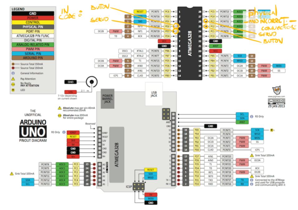
I solder two female connections to these pins and re-connect my components to their correct pins. I figure out that the mistake I made was a confusion between PC2/PC3 and PD2/PD3. I will correct the routing on my board later - perhaps I will have to modify a few things for the next assignment, and I would rather make all changes all at once.
I get rid of the Wiping mode in the code in the main loop, then bootload and upload (I have to bootload the microcontroller every time I want to upload some code) the code successfuly. The result is successful : RFID cards are read, recorded, and trigger the right reaction from the NeoPixel LED and the servo. The input of the button also works successfuly!