Attending the Fab Academy in Barcelona, I document each week of intense learning as I come across new digital fabrication techniques.
This documentation is as much a report of what I do as a reflection on why I do so, and will hopefully guide me back to Oceania to spread and make good use of the knowledge gathered along the path.
--- summary of the assignment ---
objective :
Make an in-circuit programmer by milling the PCB (program it, so that you can use it to program your board in Electronics Design week, and in other weeks). Optionally, trying other processes.
what I did :
From a designed circuit board, I generated, milled and stuffed a programer.
download :
Learning outcomes :
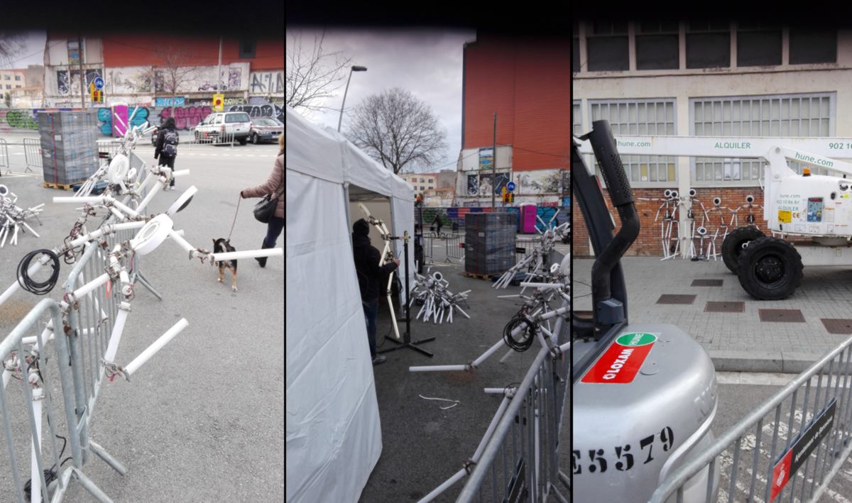
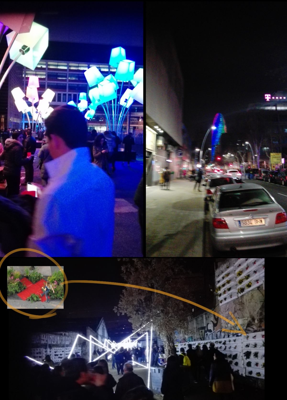
15.02.18 / We are diving into the reduced-scale world of resistance, capacitors and led. The timing is ideal, since the festival of light is on in Barcelona, an annual event in Poblenou which will keep the barrio awake at night using tons of electronics and LED. I keep on walking past many setups around the area, preparing for this weekend's festivities:
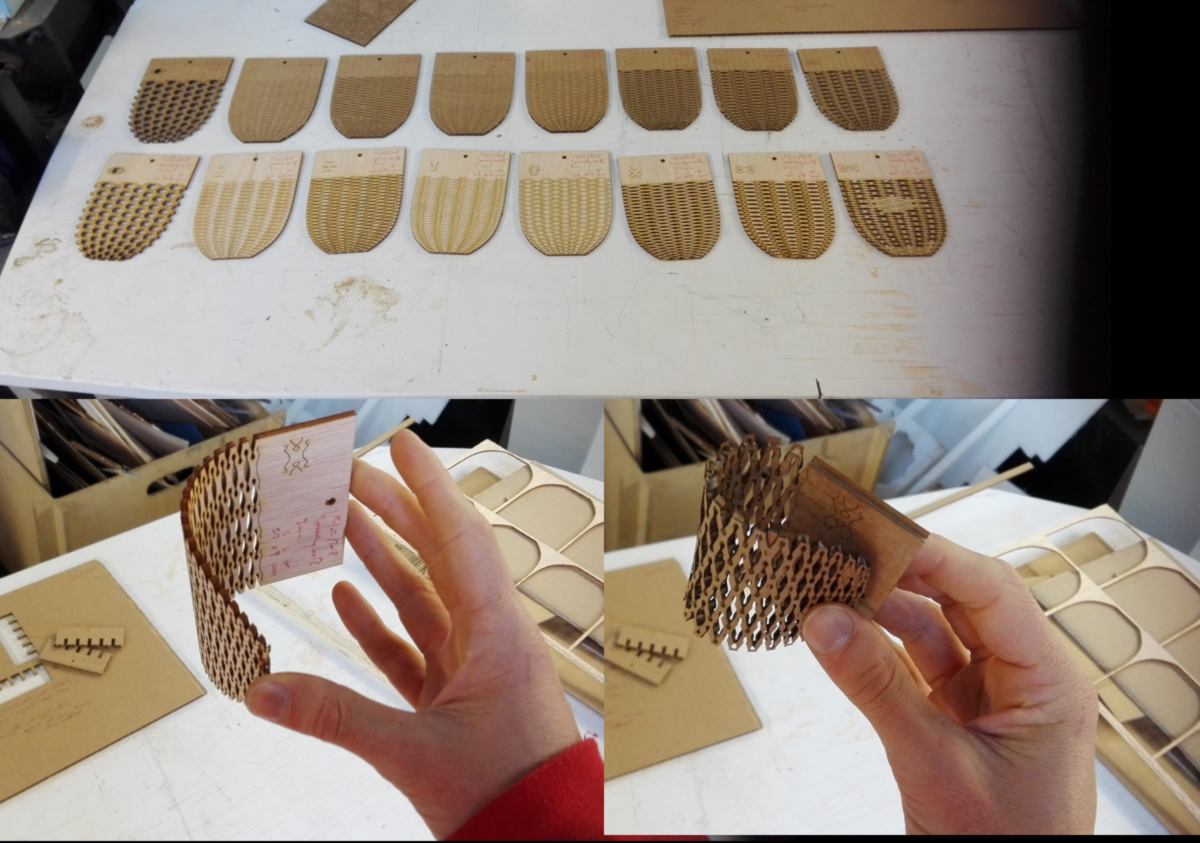
At home, I have fed my obsession for lattice "living" hinge systems. I like how the material itself can be "reprogrammed" to accept distortion. It is in many ways superior than adding connectors or hinges. I cut a few samples on both cardboard and plywood for testing purposes :
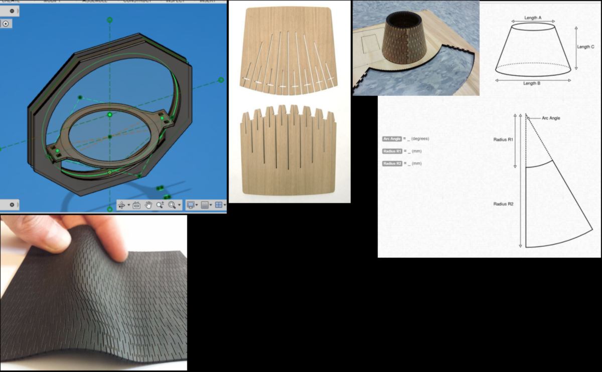
I have also moved on with the design of the green wall and think of using a cone made out of cardboard or plywood. I seek a way to calculate the flat shape which, once put together, will make a perfect cone :
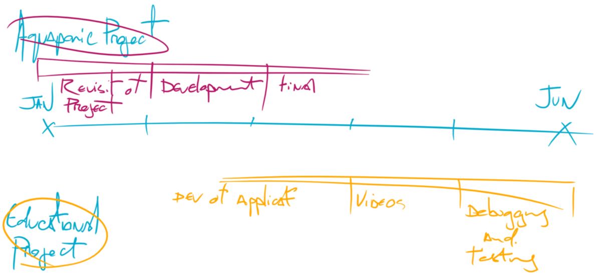
I have reviewed my overall planning for the next months. Going through weekly assignments requires time, I must drop my expectations about working on my final project straight away. I decide to develop a working prototype first, learning different techniques as the program unfolds. After a few months, I hopefully will be more comfortable and faster with these tools, and able to develop the content for the educational project. I have also heard back from Laura Cipriani, and I am looking forward for our future chat.
In the last two days, we have covered two introductory classes about electronics, one about production, the other covering general concepts around computers and electronics. We have discussed coding languages, different types of microcontrollers and more.
On the same day we have had an intro of Grasshopper, Firefly and other plugins. I am looking forward to follow these tutorials soon. My end goal behind using Grasshopper is to design my green wall into a fully parametric design, defining the number of plants and size of each individual location according to how much space is available in the projected space.
16.02.18 / Joris and I are meeting up early to get used to the PCB cutting workflow. Joris has been personalising his PCB yesterday and he is ready to etch and cut it. We discover that the PCB from yesterday's lesson has been left in the milling machine already etched. We take the opportunity to finish the job and cut it out. But first, I get aquainted again with the set of tools available :
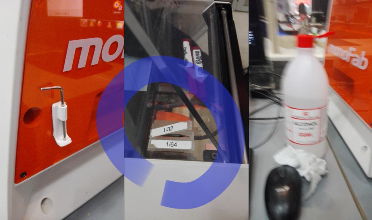
The precision milling machine we will use for the next few months is an monofab SRM-20 from Roland which manual can be found here It has a maximum axe operation of 203.2 x 152.4 x 60.5 mm and an adjustable rotation speed up to 7000rpm.This is quite impressive for a compact (451.0 x 426.6 x 426.2 mm) desktop machine. It will prove to be one of the most reliable machine of the lab.
When changing the end mill, there is a small risk of dropping it and breaking it. To get around that, Joris uses a roll of tape to pad the potential area of crash. We fit in a larger - 1/32 - end mill, launch the file designed to cut the outline out and soon after, we get our first PCB:
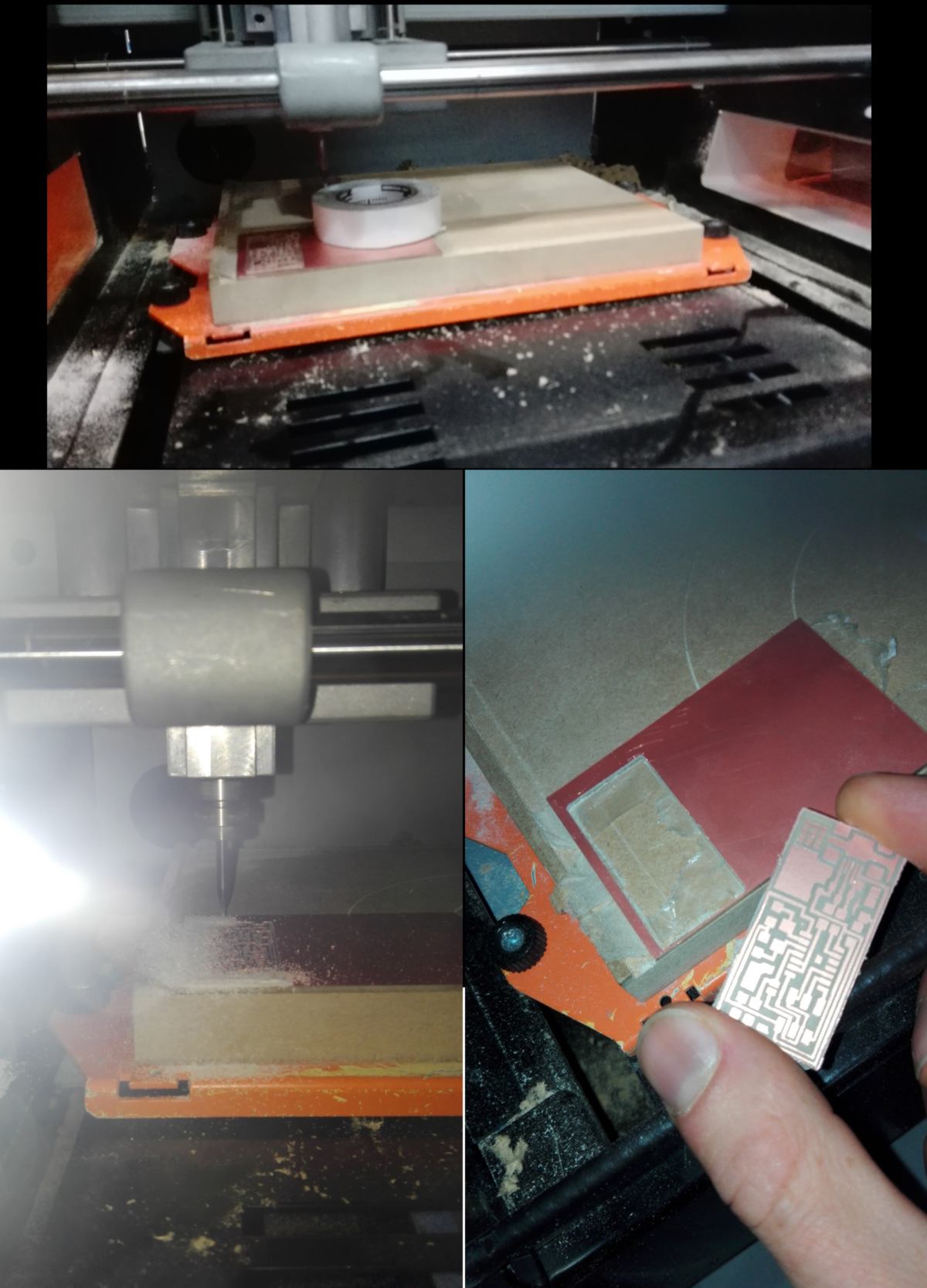
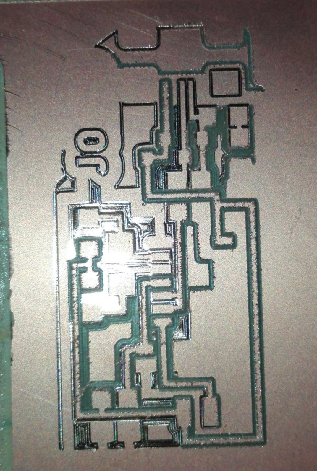
It is now time for Joris to etch and cut his own. I am tagging along. We are going to use the material already in place. Joris loads his design and begins the cut. We soon get to realise that the cut does not go through the whole layer of copper:
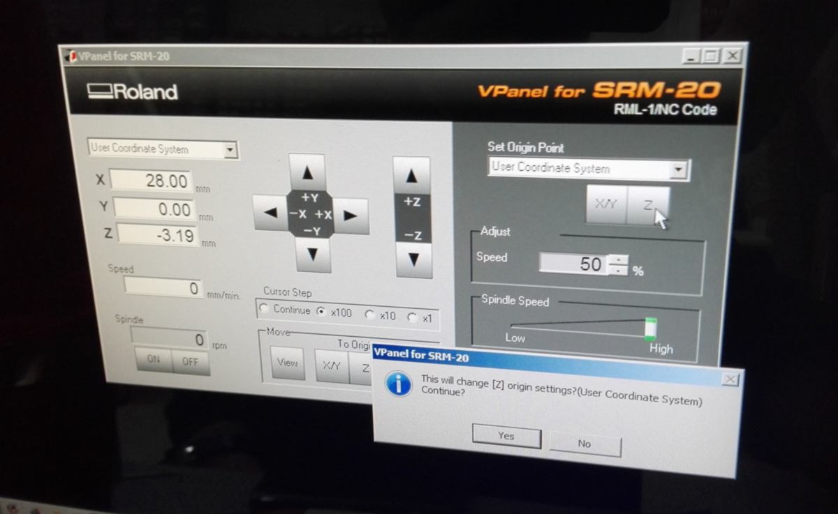
We must adjust the position of the origin on the z-axis. To do so, we select a space where there is no board, go to the origin on the z-axis, drop the position of the tool by 0.02mm, then reset the origin:
The rest of the cut goes as expected. Interestingly, due to either the PCB design or the settings for the z-axis, the tracing on Joris PCB is thiner than the initial design:
I leave the electronic room for now to run cutting and rastering tests on the laser cutter. I wish to have reference sheets for cardboard and plywood for future projects. I already have enough information about cardboard to immediately etch and cut a final reference. On plywood however, I spend time finding the right setting to get the strongest contrast possible when engraving without any traces of burns.
To do so, I initially increase the power. Once I reach the maximum setting, I drop the speed drastically. I get a result with a burnt area, so I slowly walk by way back towards faster speed. I finally get a satisfying result.
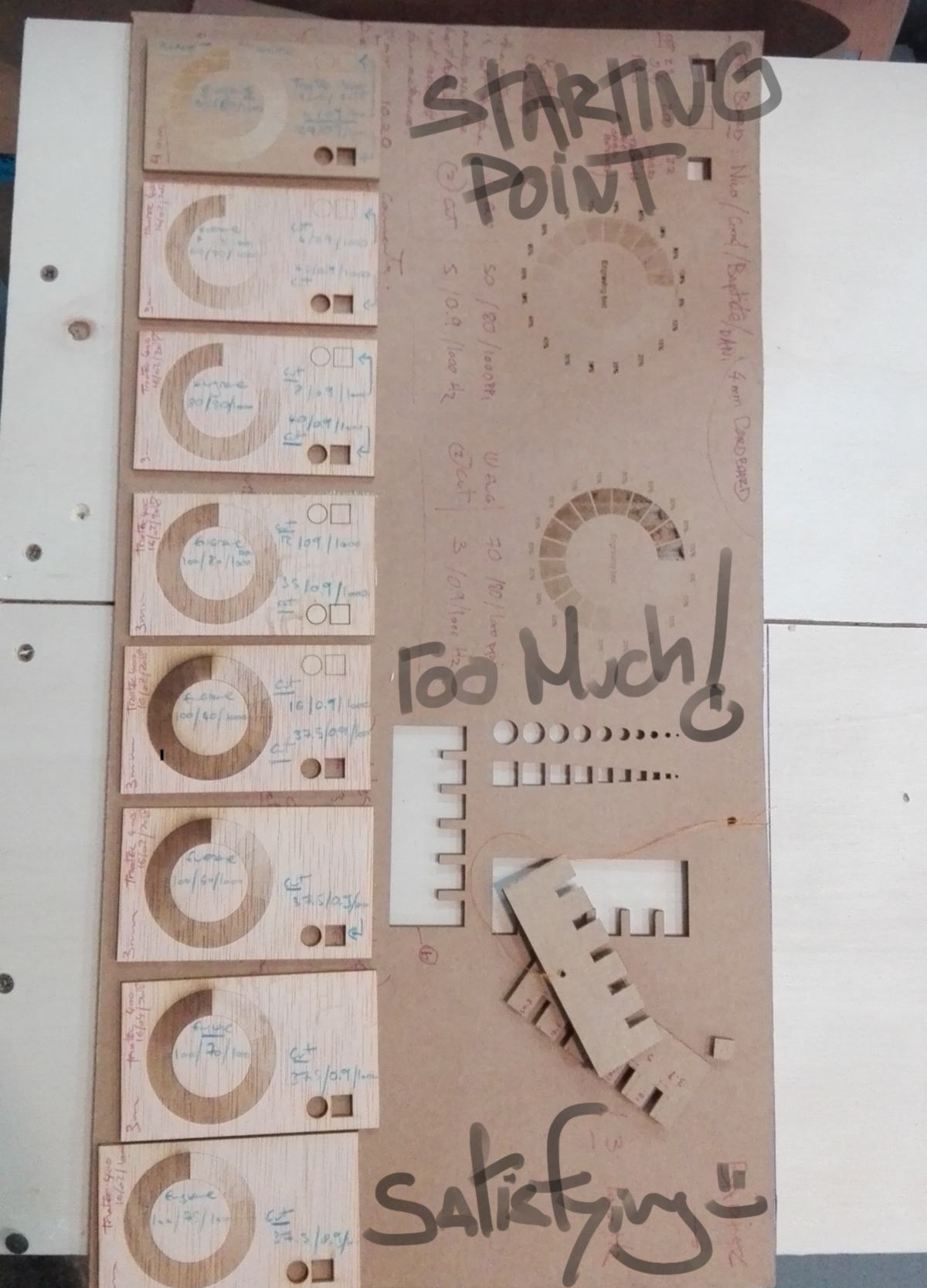
For these cuts and raster, I keep the frequency low on recommendation of Mikel. He mentions that any organic material should be cut with a low frequency to avoid catching on fire. I am also being shown a document that was hidden from us, with basic recommendations for many materials. That is a nice present to finish the week.
Joris invites me to visit a graphic design and animation school recently opened in the area. It is a new branch of a school already set up in Perpignan, where Joris has set up his Fablab. This school is absolutely sparkling, the entire building, a former printing facility, apparently the biggest one in Europe 30 years ago, has been entirely refurbished. At a larger scale, It is the whole district of Poblenou that is slowly victim of gentrification. However, with many recycling facilities around, it still keeps a very rough, industrial touch.
After a short presentation from other students, we get the vinyl cutter out to flock a few t-shirts. We are going to use a GX-24 vinyl cutter which manual can be found here. This model was first released in May 2005 and has proven to be the proud successor of 17 years of reliable and cost-effective machine for " ... producing banners, vehicle graphics, pinstriping, store displays, point-of-purchase materials, informational signs, backlit displays, flock heat transfers, stencils, and almost any other cut vinyl graphic.".
Now that I have been introduced to some concepts commun to all CNC machines, the vinyl cutter seems intuitive. We load the material, which width is automatically detected by the machine. We run a few tests (there is a button entirely dedicated to it, how convenient!) until the depth of the cut is set up correctly. We then run a second test with a text, which, apart from the flocking stage, is successful.
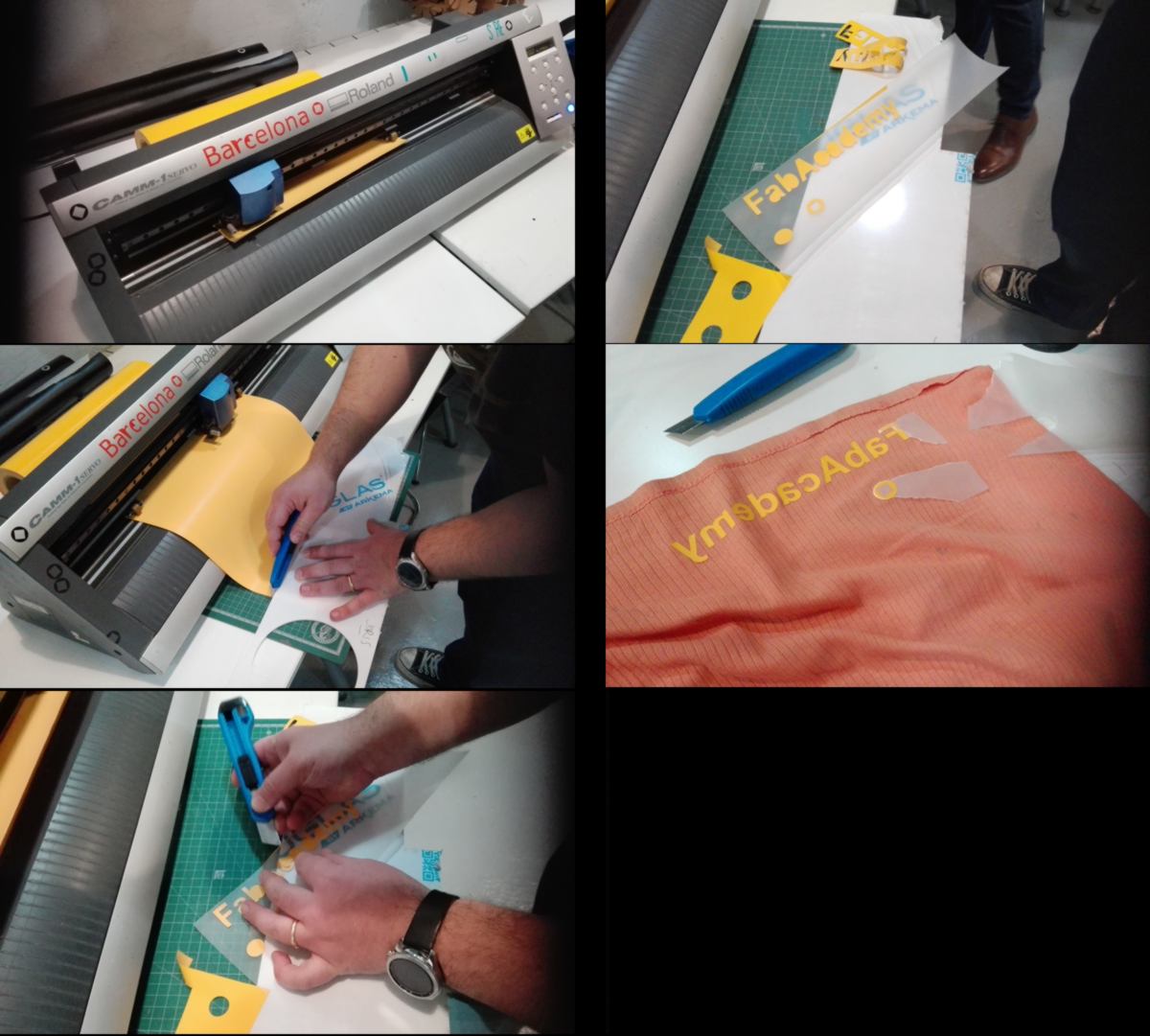
It is time to make my own TShirt. I find a black and white silhouette on the web, modify some bits and pieces and turn it into a vector using Inkscape. Copying and pasting from Inkscape to Cut Studio, my design is ready to be fed to the blade. The only unusual extra step is to "get the width" from the cutter, ensuring our design will fit in width.
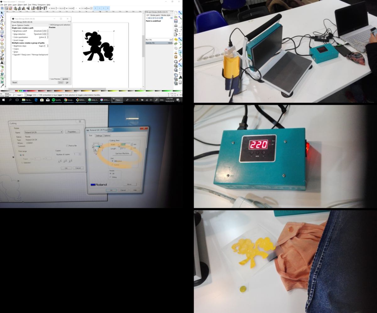
While the cutting works fine, I struggle to flock my tshirt correctly. somehow I cannot seem to get the right temperature rise for the correct duration. The design tends to stick to the plastic rather than the fabric. I cut an extra shape to try it out later on at home.
Meanwhile outside, the festival of light has begun, and I get sucked into the crowd, drifting from one installation to the other. I notice than the installation of Natalie Jeremijenko has been relocated in a community garden in Poblenou, extending the duration of her formal exhibition at the CCCB. Her emblematic design, a red cross, is easy to spot and remember.
18.02.18 / Another menu for the website is overdue. After a few weeks, the content has grown expotentially, and the reader must have faster access to each week. So far, readers must scrool down a page to get access to the next week.
As a shortcut, I will add a sub-menu to the menu I already have, and give it a polish. I find an example of drop-down menu. I add it to a test-page, and give it identical visual identity as the rest of the page:
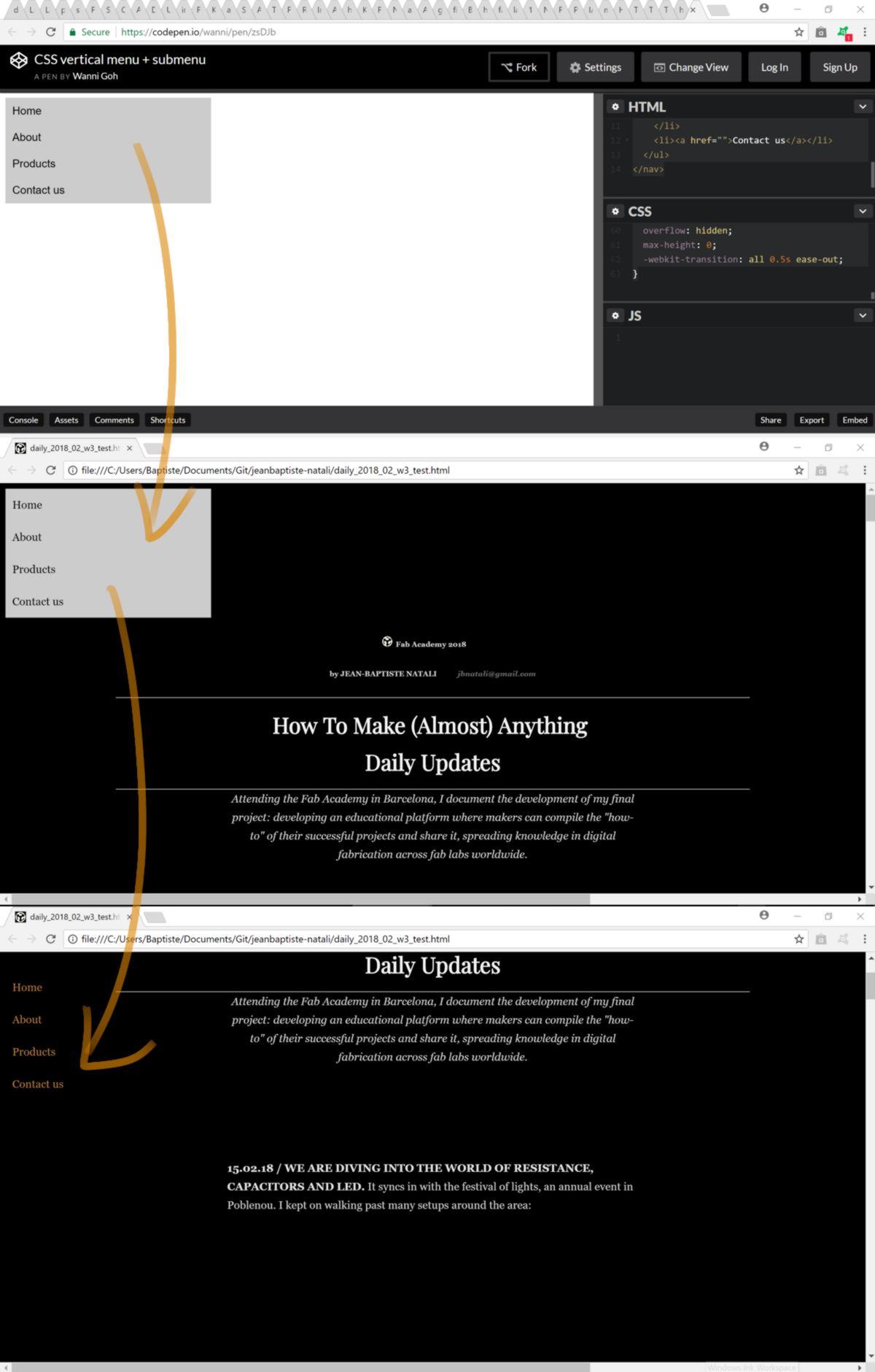
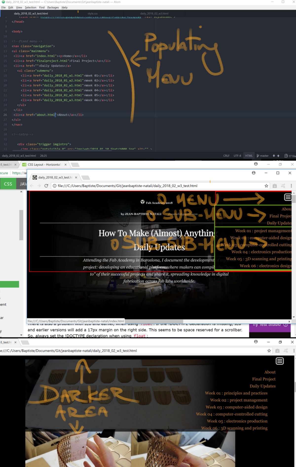
I populate the menu with all sub-menus required. I wish to keep the menu as minimal as possible, so I make the menu icon the top of the hierarchy. It will be the only thing showing when the reader scrolls down. When hovering, the reader will have access to 3 options : "about", "final project" and "daily updates".
Each week requires its own link, therefore I need a sub-sub-menu under daily update. Studying the code, I create a new class called "subsubmenu" and generate a new menu under the current menu. This way, the reader is not overwhelmed with links as soon as she/he/they hover over the icon menu.
Similarly to the former menu, I relocate the new menu onto the top right-hand corner of the page. This location has become the current norm for menus, and is out of the normal reading direction (according to "universal principles of design", a diagonal traced from the upper-left-hand cormer to the bottom right-hand corner).
Finally, I add a slighlty opaque background to maximise the readability of the menu and create a clear separation with the rest of the content.
Although I have added increment from the right-hand side, The text does not look organised. The fact that each line is individualy aligned with the right-hand side creates a steps-like effect, and it makes it difficult to grasp the organisational layers. I decide to center the menu. To me, it looks more natural.
I encounter small bumps on the way. For example, it takes me a while to understand the source of the indent in my menus. I realise that my menus are lists, and, by default, lists have indents. I get rid of this by specifying it in the code, getting rid of the default style of the list ("list-style: none;").
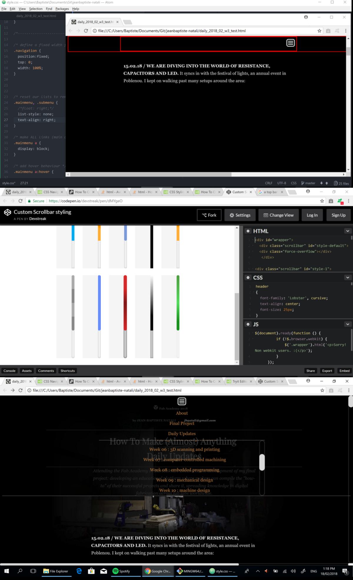
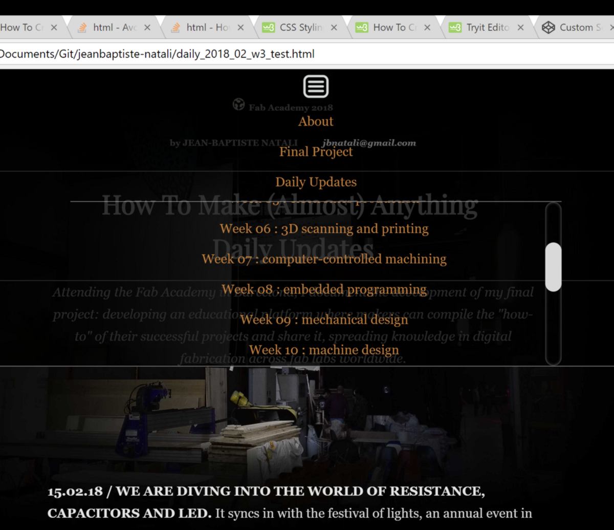
Since the menu is "fixed", It cannot be scrolled down. This is an issue since I have to fit one sub-menu for each week, and they are 18 of them. Therefore I decide to add a scroll bar to the sub-sub-menu. The style of the scroll bar by default does not fit the style of my website though. I find a description of personalised scroll bar, import and adjust it to fit my website.
The menu is ready, and I copy-paste it to all pages of my website. I have looked into a way to propagate a single piece of code to many webpage, but the only smart way I found was in php, which is not acceptable for security reason, according to the Fab Academy Gurus.
I also look at the website on my phone, and it is barely usable. My website is not responsive. It is a problem, I keep it for later.
19.02.18 / I draft a funding application for Fab Lab Akld. In collaboration with other charity organisations and a hackerspace, we put together an application to get some money and buy the basic tools for the lab : laser cutter, CNC machine, etc. A Fab Lab seems to match the focuses of this funding: young people, education and digital enablement. I previously approached The Spark Foundation for a smaller-scale project: setting up a small-scale, mobile Fabrication Lab.
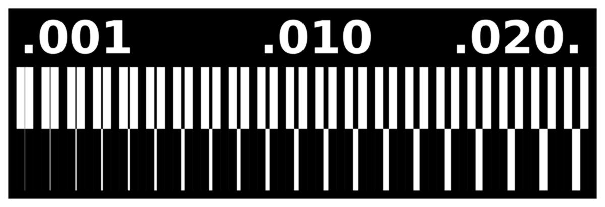
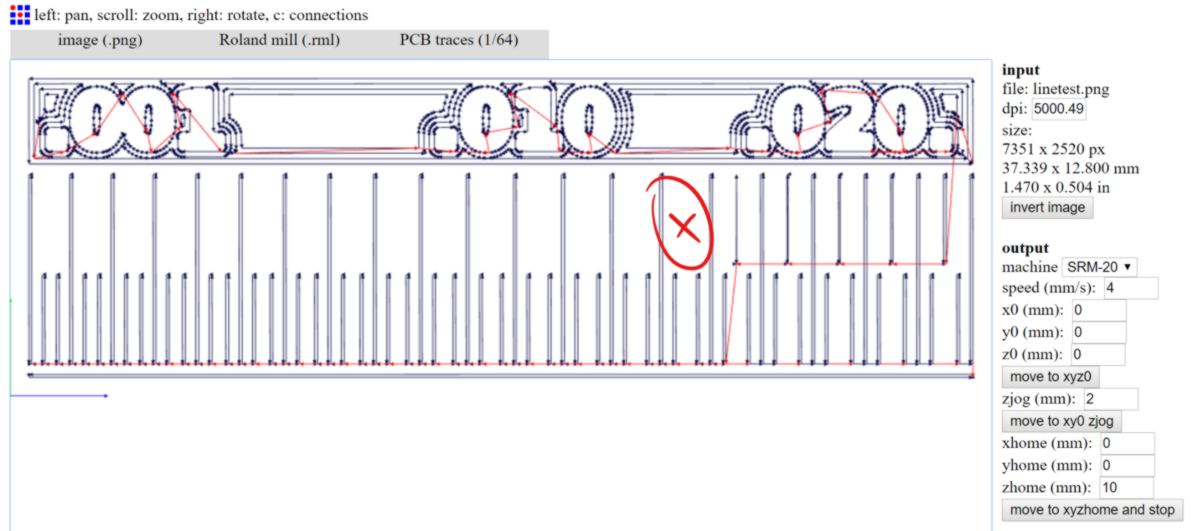
Back to the Northen Hemisphere. As a group, we are going to test the limits of the PCB milling machine. By cutting the design below, we can test the definition of our machine :
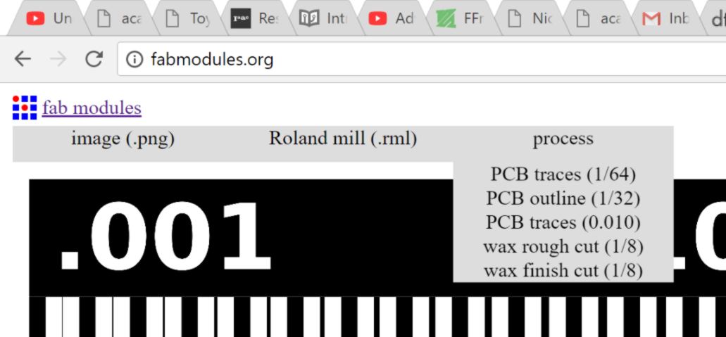
Firstly, we import the .png into the fabmodules website. Then we specify the output format - here a Roland milling machine (.rml). For the traces, in the process dropdown menu, we specify the type of end mill used, here a 1/64inch (0.4mm) wide end mill:
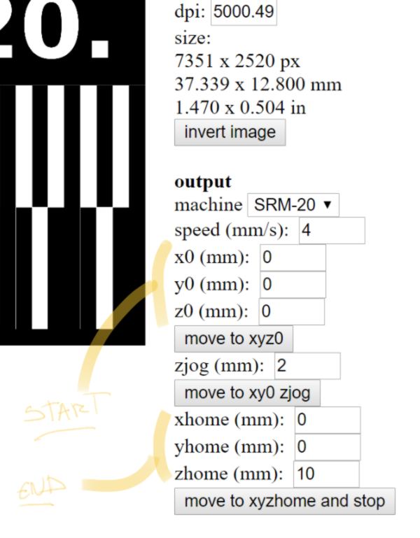
then, after checking the size of the board, we specify the starting point of the milling process. Here, we want the origin of our milling process to be equivalent to the origin we will set up on the machine itself, therefore : "0,0,0".
Once the milling end, the end mill will go back to its neutral position. The trajectory between the last point cut and the neutral position might go straight through the board. To avoid the end mill and board to be damaged, we set up an extra translation upwards, ensuring the end mill is fully away from the board before heading back to its neutral position:
As an extra finishing touch, we could ensure the extra area of copper present on top of the board are etched. However, it extends the cutting time, therefore we decide to go with the number of offset by default:
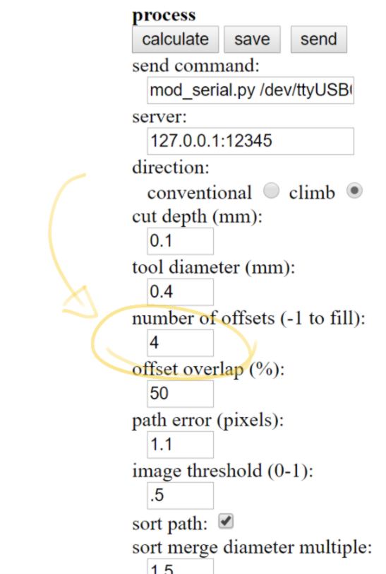
We calculate and save the g-code for this cut. We can already see that below a specific value, the end mill is not able to follow the initial design.
Using similar workflow, we prepare the cut of the outline. A few settings differ :
we are saving our .rml files to the IAAC Cloud and head to the milling machine. This time I am in charge of operating the machine, and help the rest of the group. We select a board and verify it is straight, then stick it to a sacrificial layer using the same weak double-sided tape as with Joris.
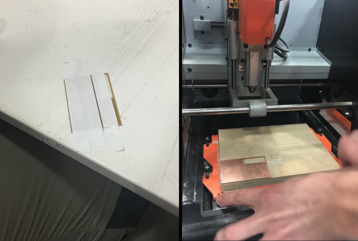
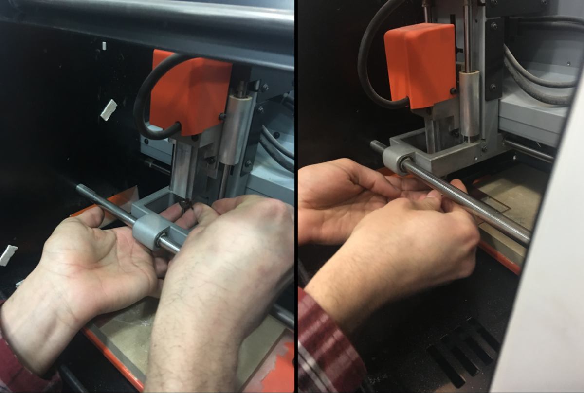
We then load our cutting tool - 1/64 - and tighten it gently. We align the end mill a few millimeter away from the bottom left-hand corner of the board and set up our x/y axis. We then slowly move the end mill down until a few millimeters away from the stock, unlock the cutting tool to gently let it rest on the board. This is our origin on the z-axis, and all cuts will dive into the material from there. We lock the cutting tool again and raise it a bit to avoid it to scratch the board while being moved on the x or y axis.
Now the calibration is done, we prepare the machine for the cut. First we drop the speed and ensure the spindle is at full power. Dropping the speed will give us some time to check whether the cut is deep enough to go through the layer of copper. We then load our file and start the cut.
Pausing the cut and using the View command, we notice that, similar to what I experienced with Joris, the cut is not going fully through the layer of copper. We have two options : modifying the depth of the cut in the .rml file or dropping the origin of the machine on the z-axis, lying to it in order to cut a little deeper.
Since we are all gathered around the machine, we choose the second option. This time, we pretend that the board is as large as the cutting area, and therefore we have to mill down to set up the origin on the z-axis deeper. We switch the spindle on and slowly cut through the material, dropping the end mill at -0.1mm. We set up the new origin on the z-axis there, move back up and restart a new cut. This time, it goes through the layer of copper just fine. We are aware that the end mill, being quite deep into the material, might experience more side-pressure than intended, so we keep the speed low.
We then cut the outline of the test. Before doing so, we reset the origin of the z-axis back to its initial position. It cuts straight through. However one side was not calculated correctly by fabModules, so we simply unclip it out of the board.
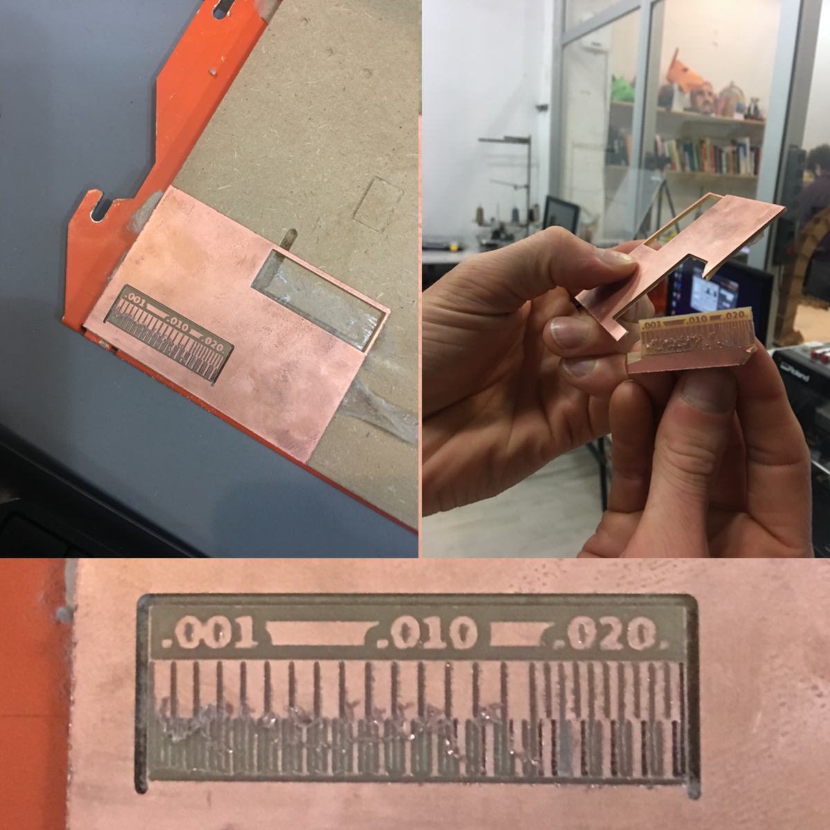
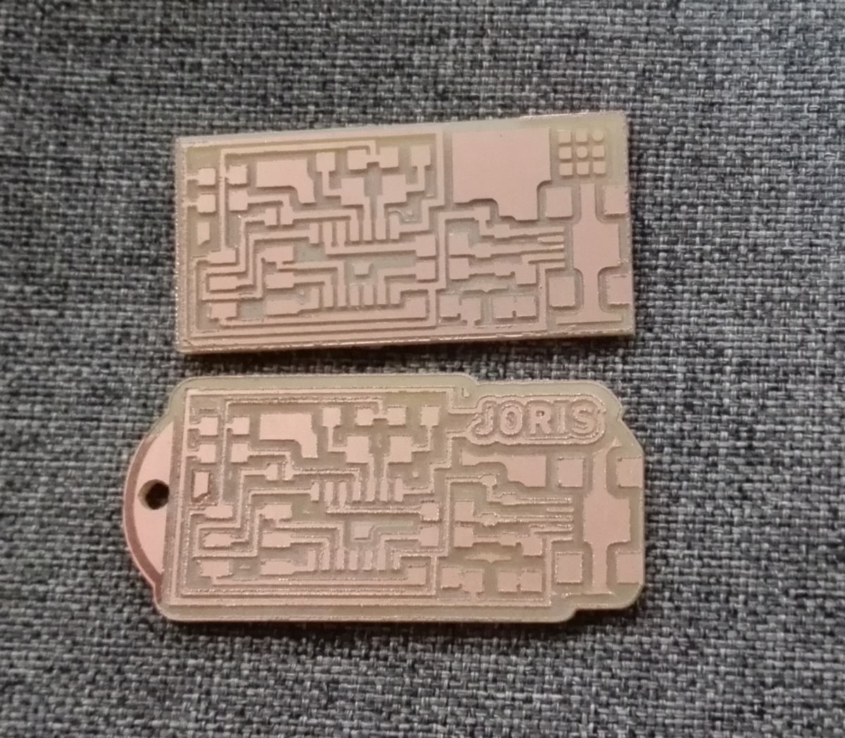
We can clearly see the limitation of the machine. What can be taken from this? The top line shows the minimum distance required for two traces to be correctly separated by a cut. We can see that under .015, with our current setting, the precision milling machine can not cut this separation.
The bottom line tests the minimum thickness required for a trace. Under 0.010, after I clean up the board by scratching it gently to get rid of residues of copper, traces do not keep their integrity.
To sum it up, with this machine, and using these tools, I must keep my traces thickness over 0.010 with a separation of at least 0.015.
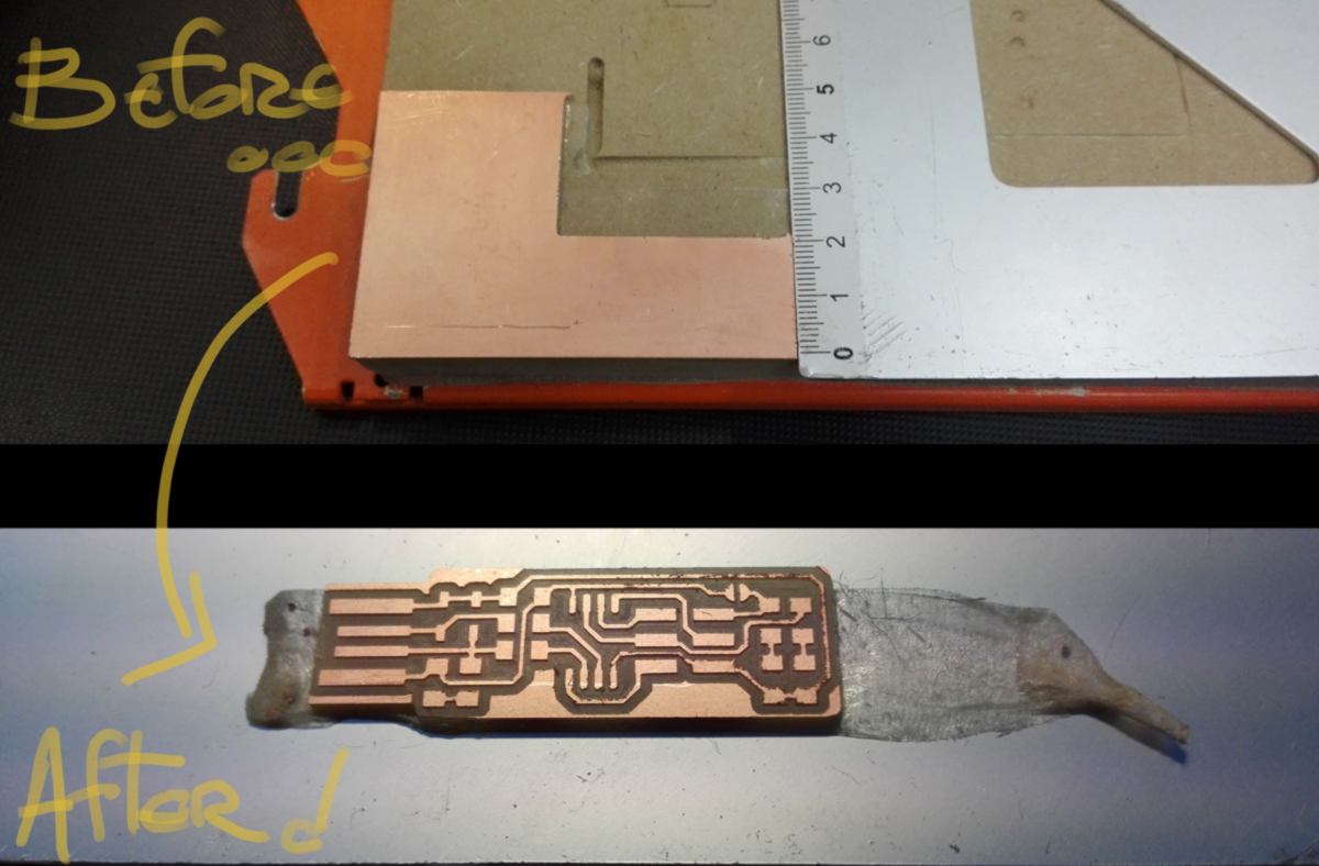
While I am in possession of the precision-drilling machine, I follow the same procedure for the ISP I selected , cutting out the circuit on a left-over with just enough space. I follow the same two-steps : tracing the circuit with the 1/64 end mill and cutting the outline with the 1/32 cutting tool.
20.02.18 / Let's put the pieces of the puzzle together. At the soldering station, I select and gather all microscopic components which will be required, as well as the basic soldering kit : solder station, 2-in-1 magnifying glass and lamp, some braid and a few test boards. I quickly make a third hand and gather some blue-tac to stick my board to the table.
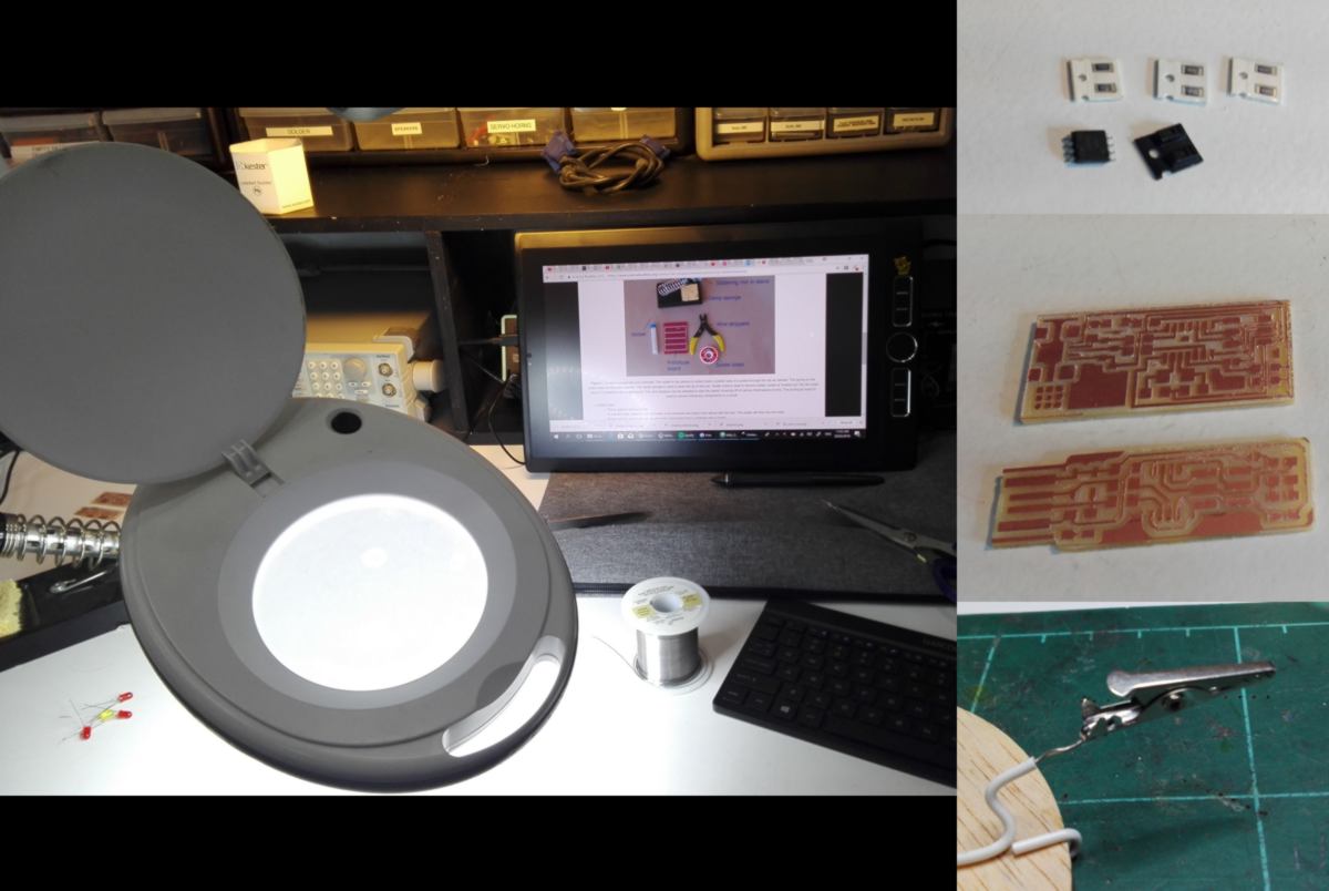
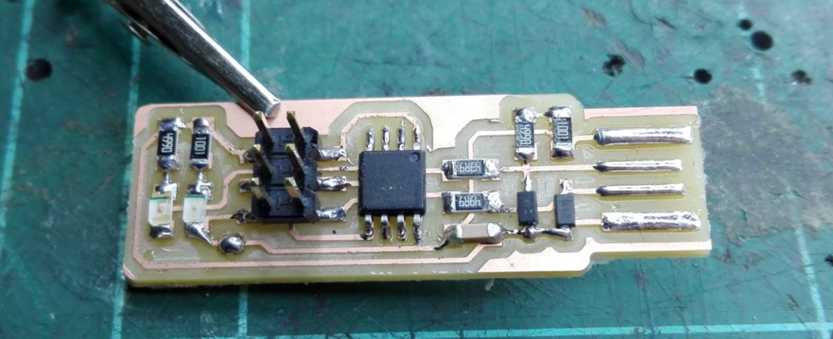
I warm up on the test boards, reading a few articles describing the 101 of soldering. As this scale, materials heat up and cool down rapidly, and it seems that the laws of gravity and friction are challenging the natural order. I then move on to solder my board, helped by the excellent documentation available to put the right component at the right location in the right direction.
As a side-note, I have followed the recommendation from many tutors to have my coffee after soldering. unbeknownst as to whether this measure made any difference, I end up mounting all components on the board:
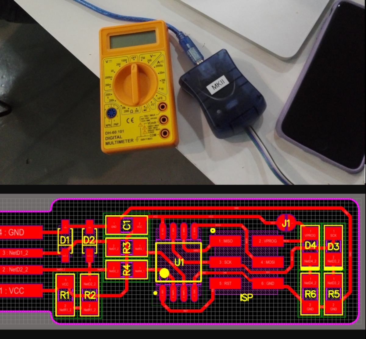
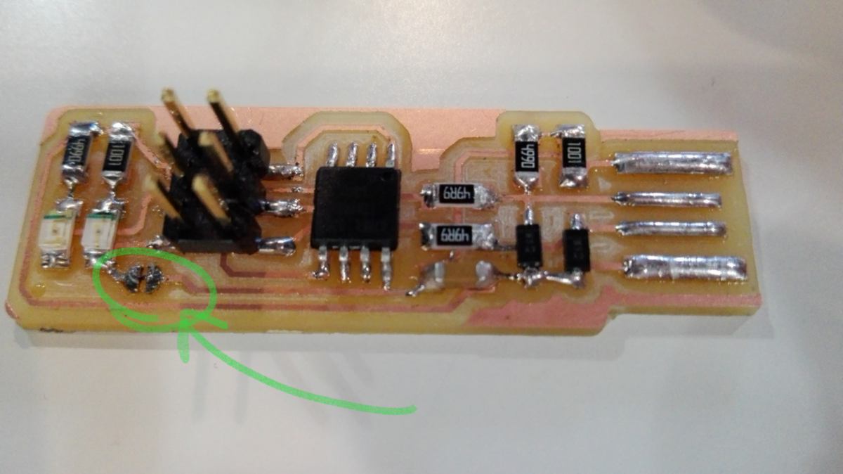
It is time to program the board for future use. During the preliminary testing, the programmer I connect my board to, a AMR mk2, blinks orange, meaning there is a short circuit happening somewhere. I start looking for short-circuits, testing every possible connection starting from the pin header and expanding outwards, using the documentation as a guide:
After trying every combinations possible, I still cannot locate the short-circuit. I re-test by board and, miraculously, the light is now green. I guess I can move on to the programming stage.
My own computer is a Wacom Mobile studio, running on Windows, with fancy next-generation USB ports which fits with nothing currently existing. Ilias offers his computer, with Ubuntu as an operating system. We set up the firmware together, specifying the ISP we use. Then, I scrupulously follow the steps described in the documentation, flashing my board, then testing the fuses, and finally turning my board into a proper programer. The last step is to get rid of the extra solder on the board so that it cannot be programed anymore :
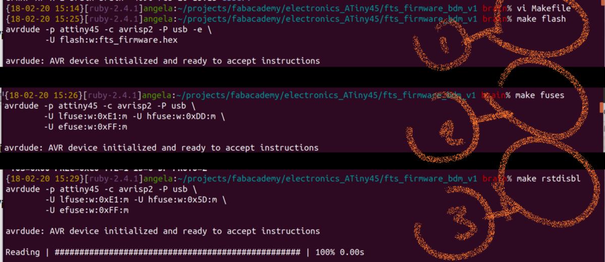
These steps have never been explained to us so I refer to another student's documentation more advanced in electronics to find out. Makefile is required to have our type of programer selected and recognised as such by other devices. We then bootload the programer and set the fuses so this board will use the external clock (crystal). We finally disable the reset function so this programmer will never be reprogramed - it will become a programer forever.
I have now a new ISP programmer ready to go. I am looking forward to dive deeper into electronics later on to better grasp the nuts and bolts of it.
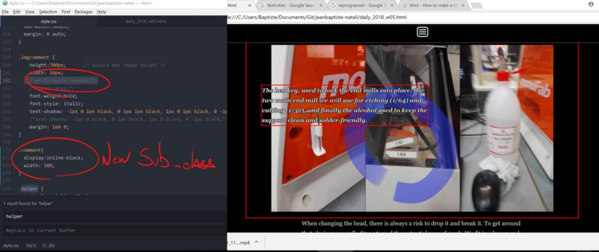
21.02.18 / To begin a new week, I tweak the website to make comments on picture easier to read :
I also proofread my daily updates of the very first week at the fab academy.
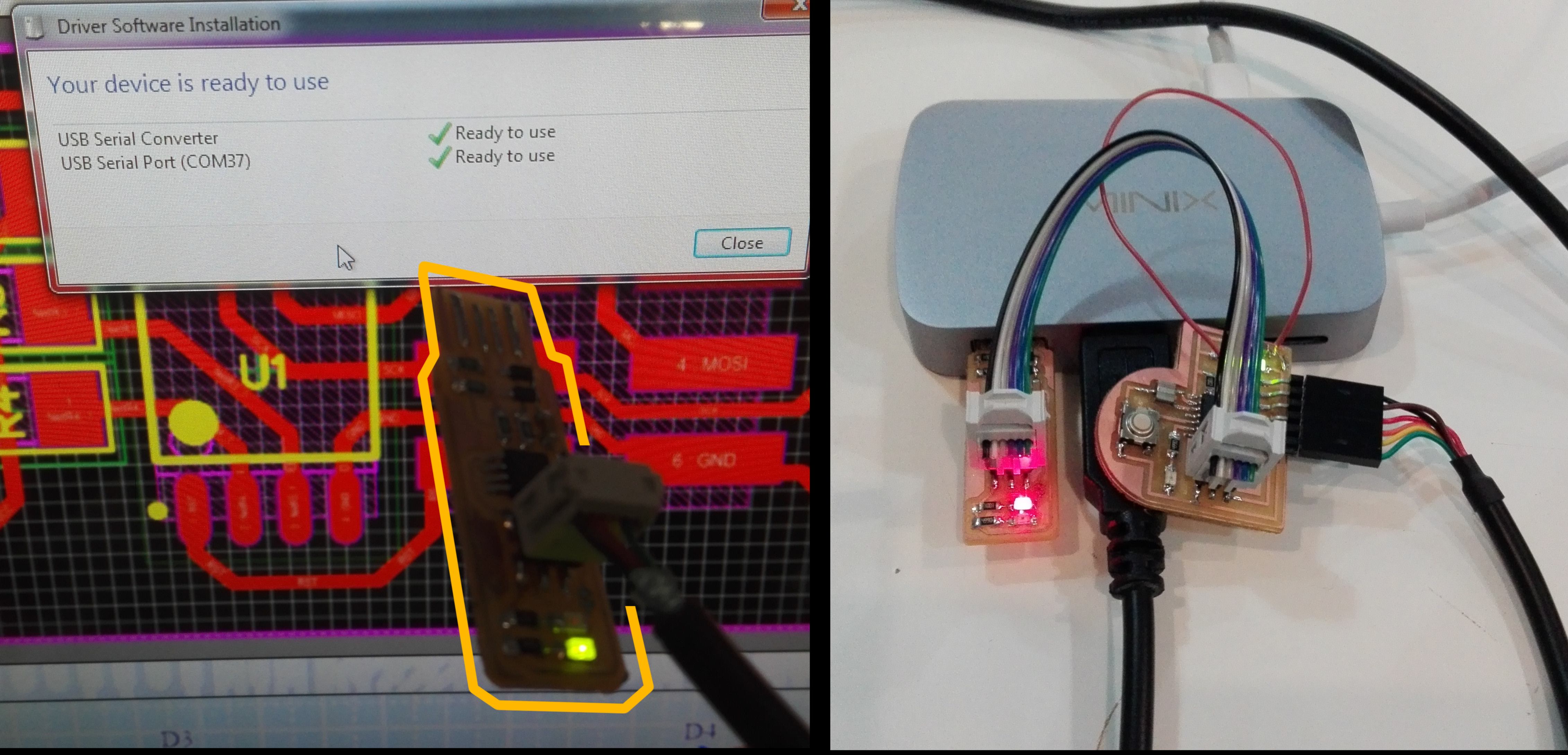
20.06.18 / LAST MINUTE ADDITIONe Here is a picture of the programer connected to a computer, and later on used to troubleshoot and bootlaod my Hello board :