Attending the Fab Academy in Barcelona, I document each week of intense learning as I come across new digital fabrication techniques.
This documentation is as much a report of what I do as a reflection on why I do so, and will hopefully guide me back to Oceania to spread and make good use of the knowledge gathered along the path.
--- summary of the assignment ---
objective :
Measure something: add a sensor to a microcontroller board that you have designed and read it.
what I did :
I fabricated a circuit board designed to detect motion. I also designed a circuit board with an RFID card reader.
download :
Learning outcomes :
09.04.18 / This week I would like to create an input system for RFID NFC card:
The idea is to be able to test the skill level of a fab lab user. I have two cards. Each of these cards has an identification number. The receiver has data about these identification numbers. One of them has a skillset that the other one does not have. The idea is that, when scanning a card, the receiver detects whether this card has these skillsets or not.
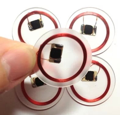
I consider using an RFID NFC card since they are small, inexpensive and only working at close range.
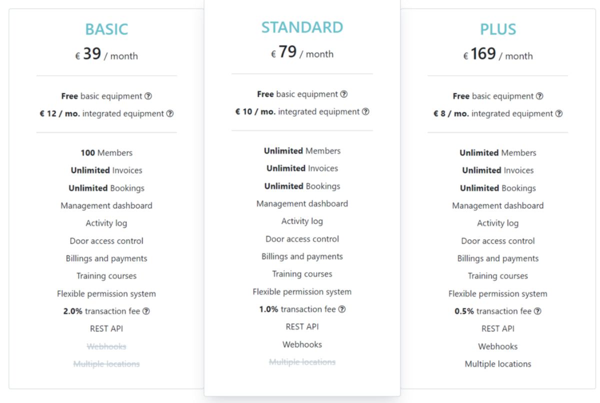
I wish to develop this system since it could in the future provide access to specific tools to fab lab users. I am aware that other systems such as fabman already exists for this purpose :

I look around for some hardware we already have at the lab :
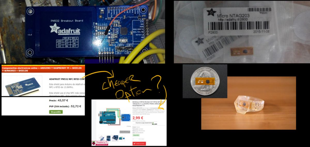
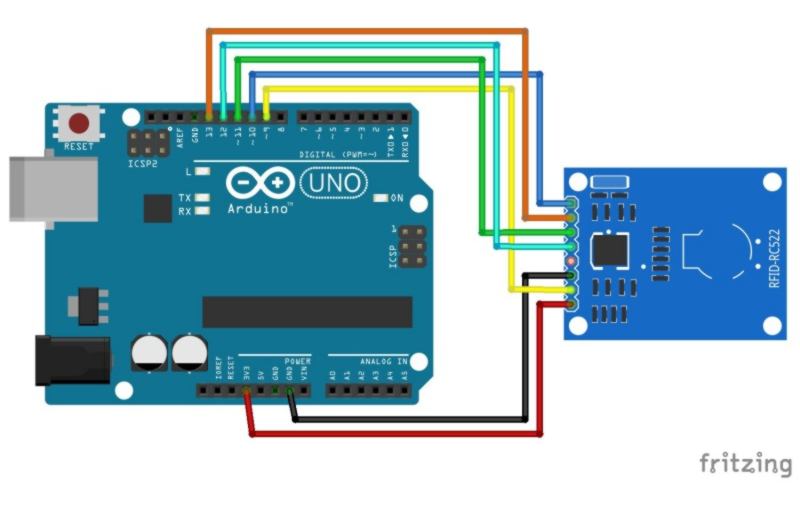
I look at projects designed with the cheap version of the card. The connections on an Arduino are straightforward :
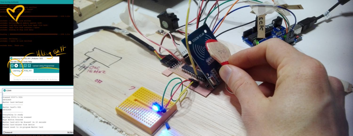
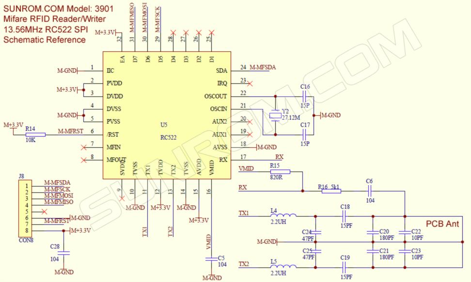
I also find an instructable that does even better than I thought of. In this system a card is used as a master card which then grants access to other cards. Below the schematic of the RFID reader :
Before I design my board, I want to prototype the system with an Arduino. I order the kit online, which is going to take a few days to arrive.
In the meantime I have to come up with another sensor.
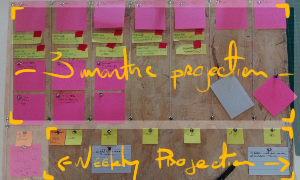
10.04.18 /Before I get started on the sensor, I am going to plan my next weeks. The Fabacademy will finish soon and I need to do some planning to ensure my final project will be ready. I reuse the board I made in January and tweak it :
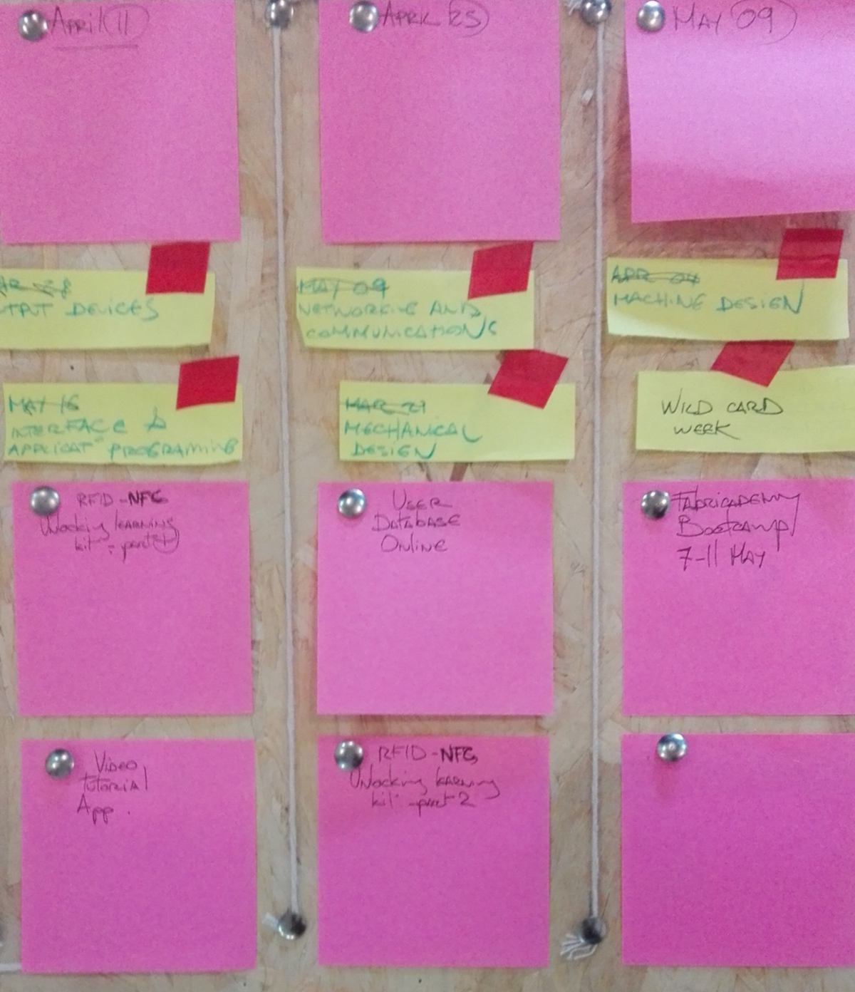
After the Fabricademy bootcamp, I can focus on content for the lessons and therefore, the learning kits.
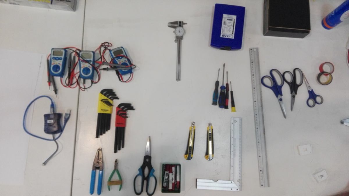
What I noticed about tools at the lab is that they get lost very often. It is time-consuming to look for them. A tracking system has been discussed, where users have tags which they place on top of the location where the tool is meant to be stored. I think of doing a tool-tracking system using RFID cards, however the first step would be to use a more analog system for testing purposes. I look at our tools and with Santi, we lay them out to see what could be set up on a board :
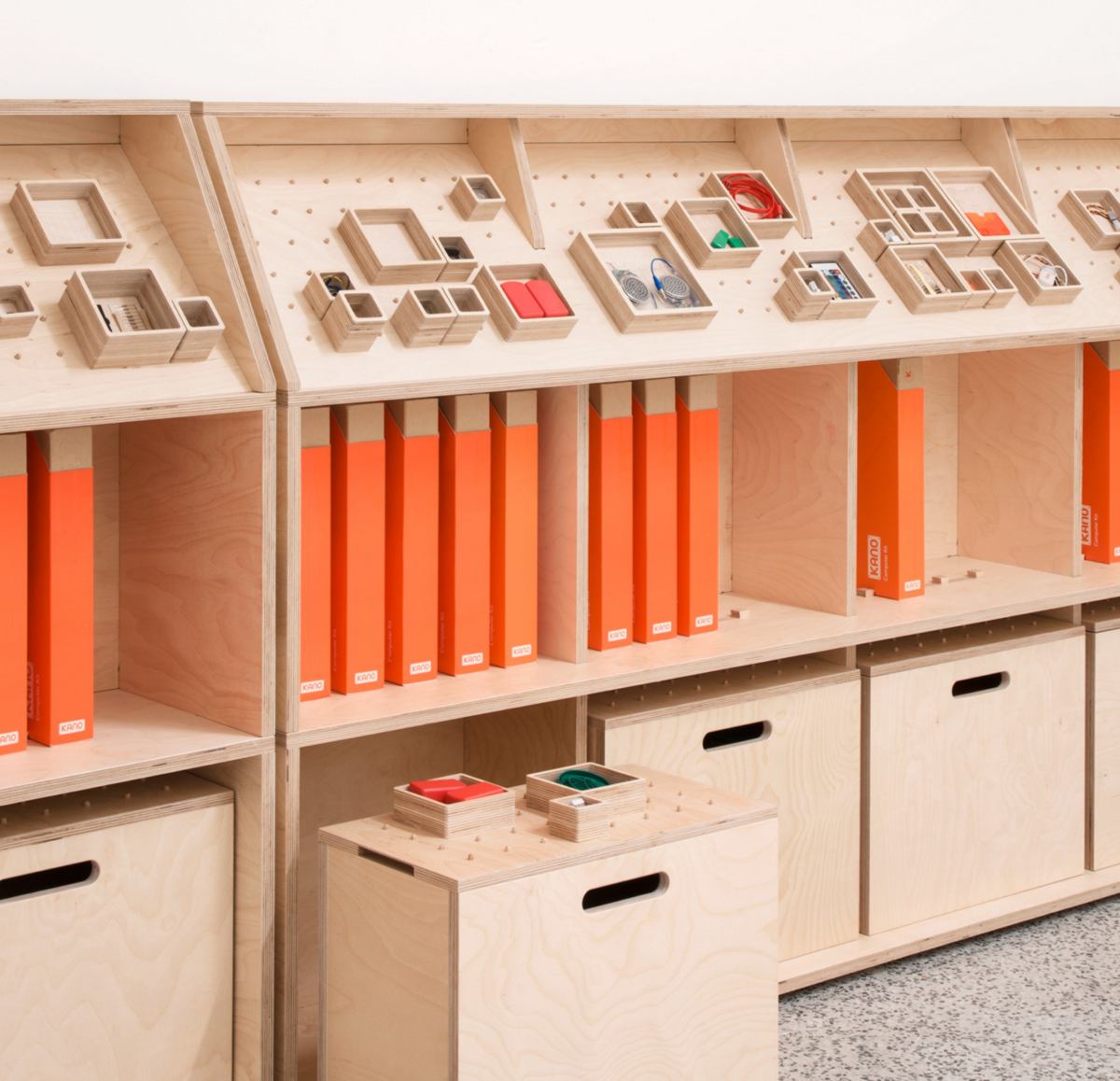
He shows me his inspiration :
I have no time to design something digitally and cut it on a CNC, so I will begin with the basics. I find a board, cut it to fit the space, add nails, screws, and draw the outline of each tool :
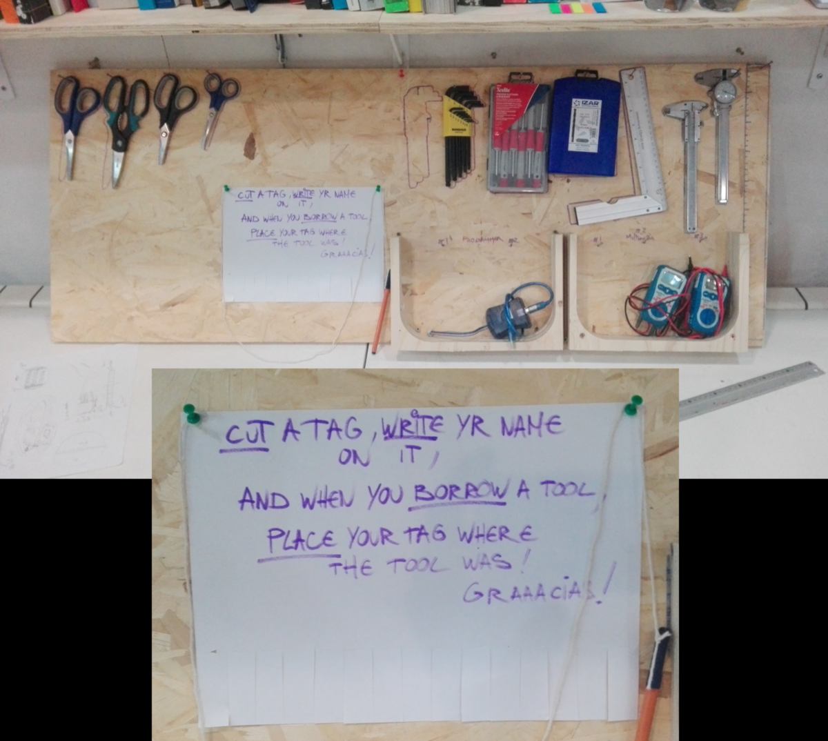
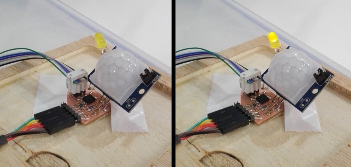
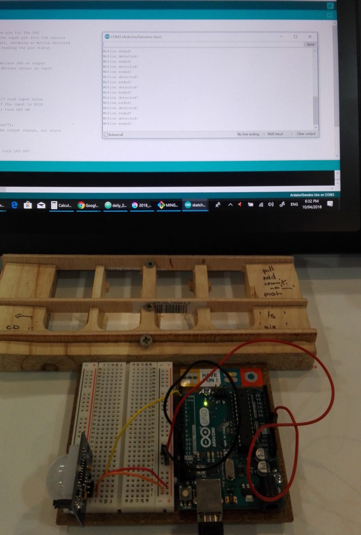
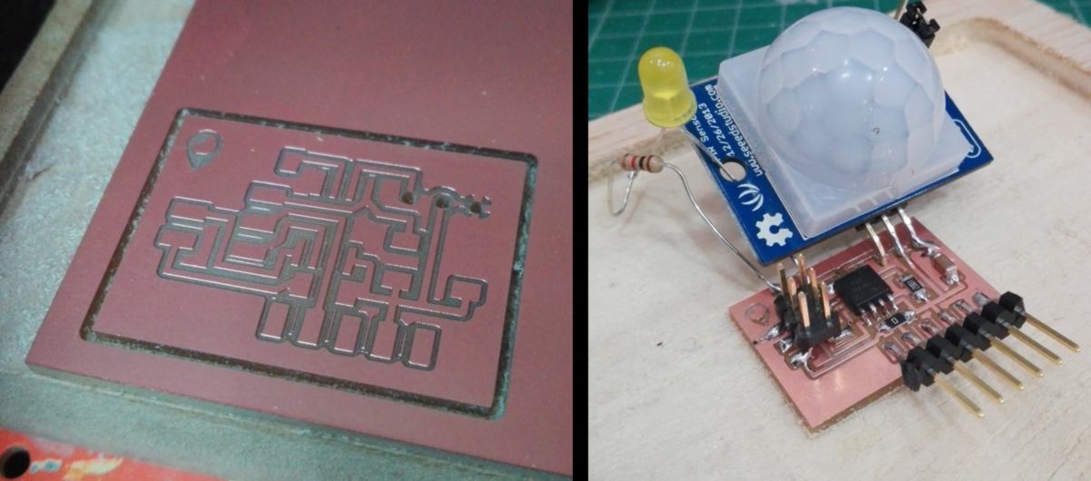
While I wait for the RFID reader, I will make a motion sensor to switch on a few LEDs when users' hands approach this toolboard. I am going to use this PIR Motion Sensor from Seeed studio :
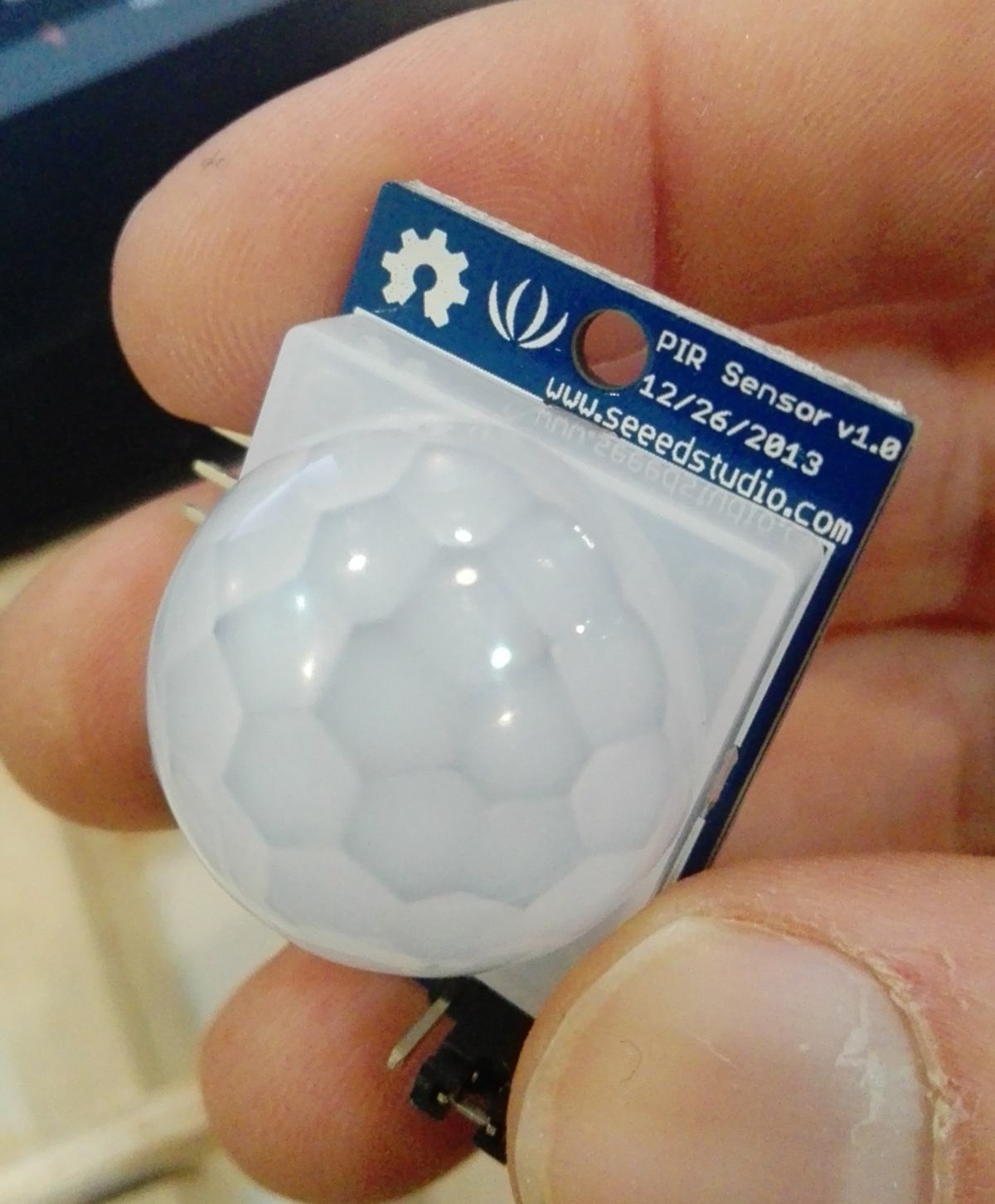
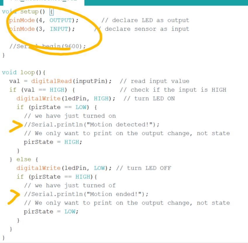
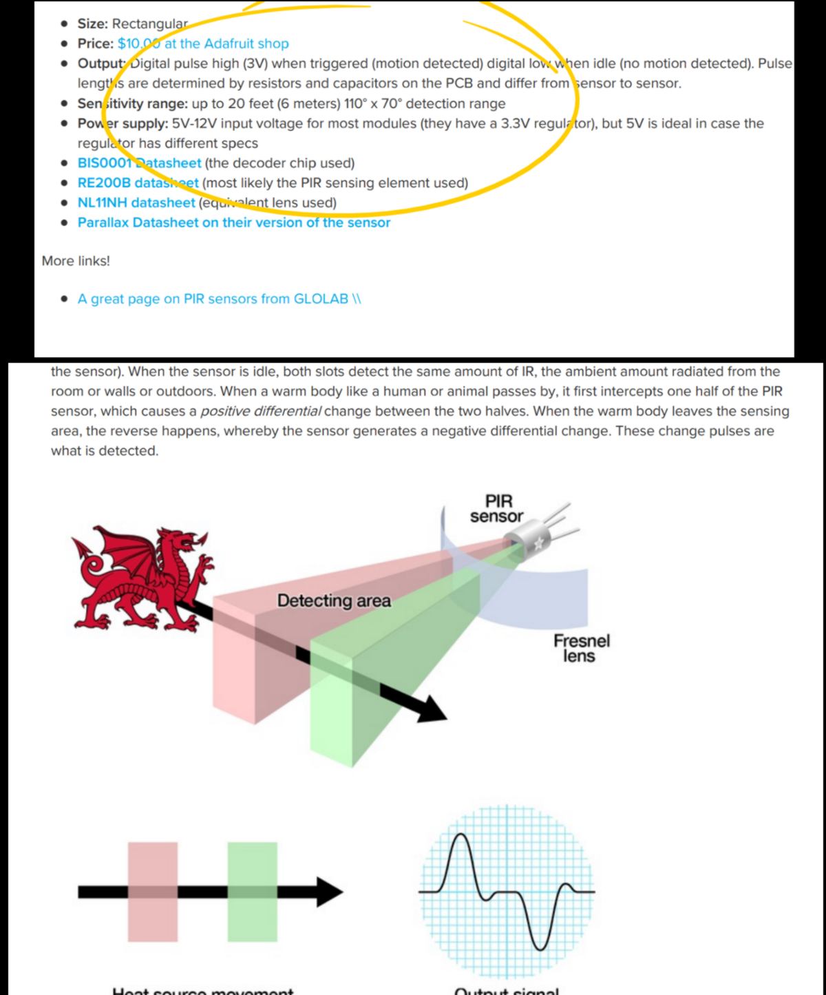
I was unable to find the datasheet for this particular sensor on Seed Studio website, but I found some excellent documentation on the Adafruit Website :
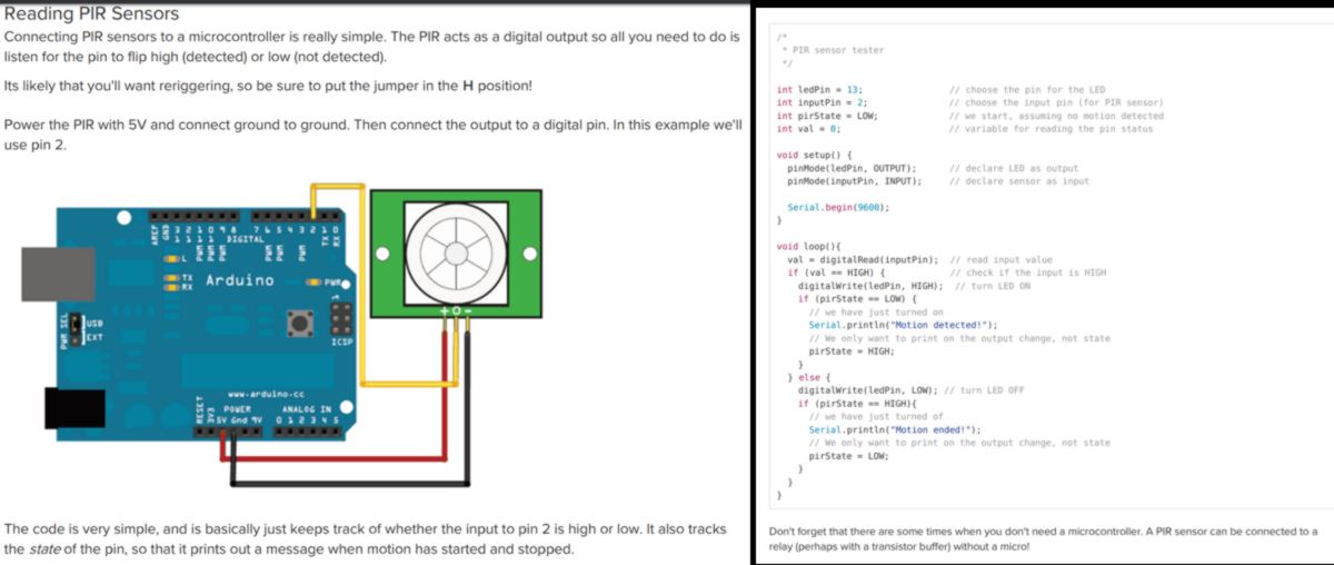
The first test is successful, the sensor is communicating with the serial monitor correctly :
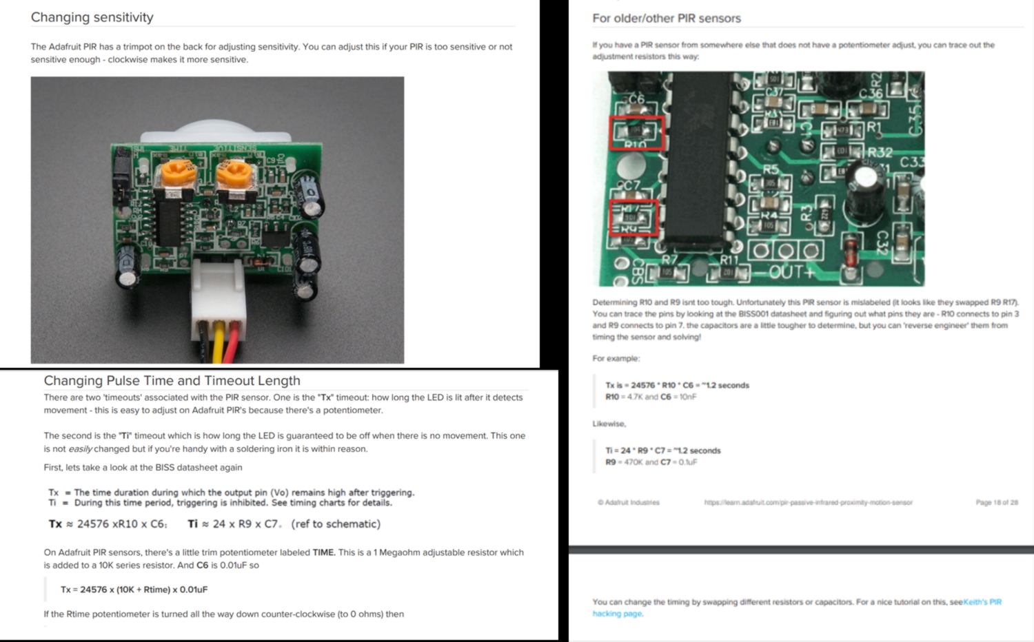
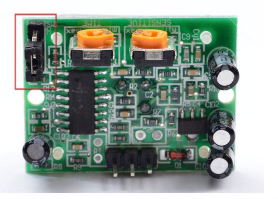
However I notice that the sensor keeps on sending changes every second or so. That comes from the mode the sensor is currently on. It is called "non-retriggering". The chip has another mode called "retriggering" where the sensor will "stay on" the entire time that something is moving. I stared at the graph on the BISS0001 datasheet for a bit without gaining any better understanding of it. In practice, the way to switch from one mode to another is to place a jumper in a specific position on the board :
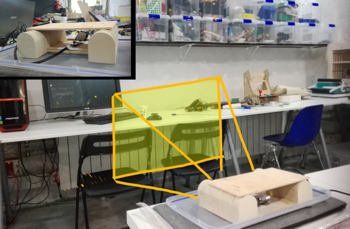
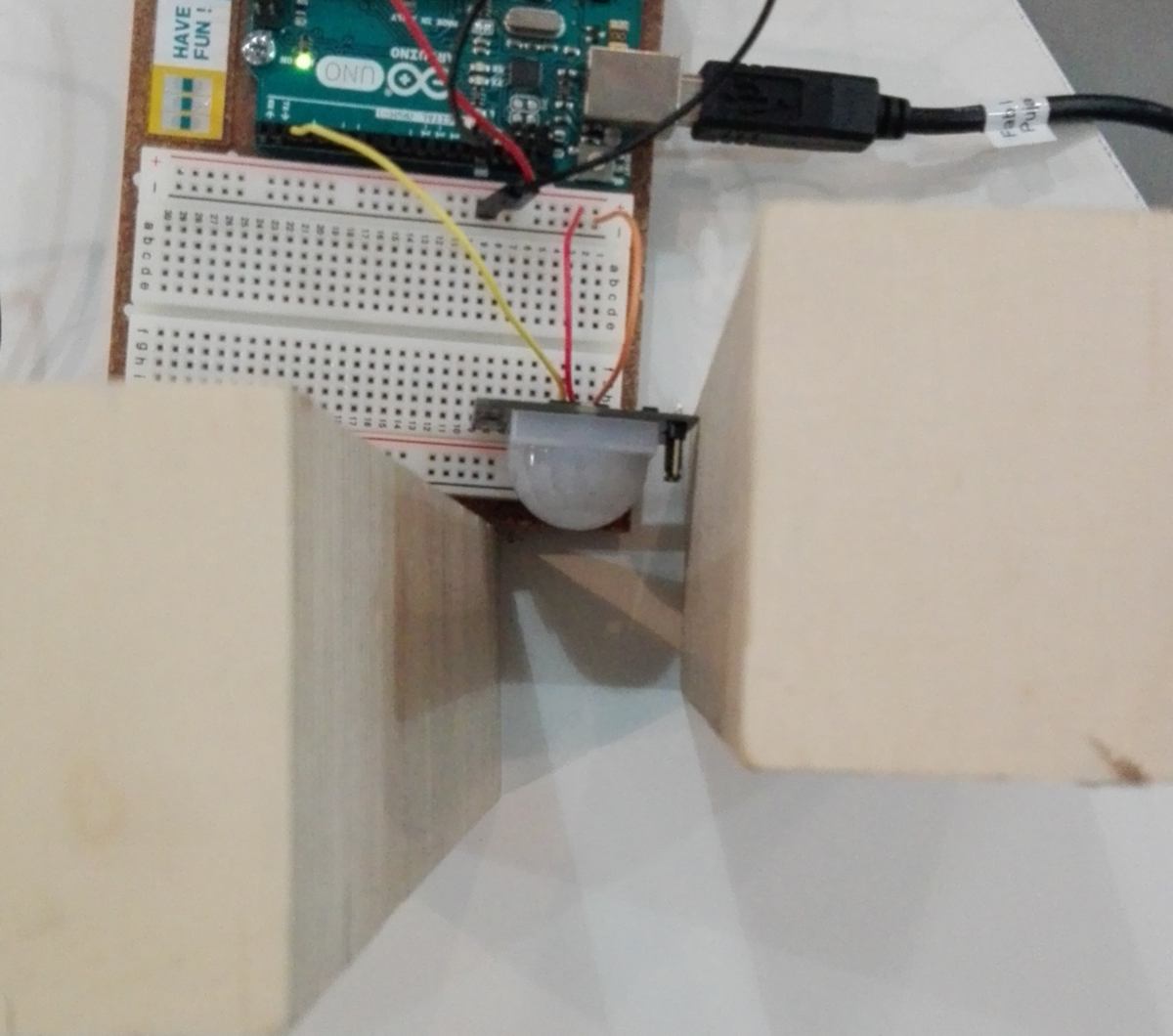
The motion detection now stays on when something keeps on moving in front of the sensor. The sensor can sense motion from metres away. I Look for a way to shorten this distance to roughly 50cm, however I cannot find any description about it. To be more accurate, what I found is a recommendation of adding an extra semi-transparent layer in front of it. Rather than doing that, I will set up the sensor at the top of the board, aiming downwards, and blinding part of its surrounding, limiting its "vision" to a narrow area. Something similar to this setup :
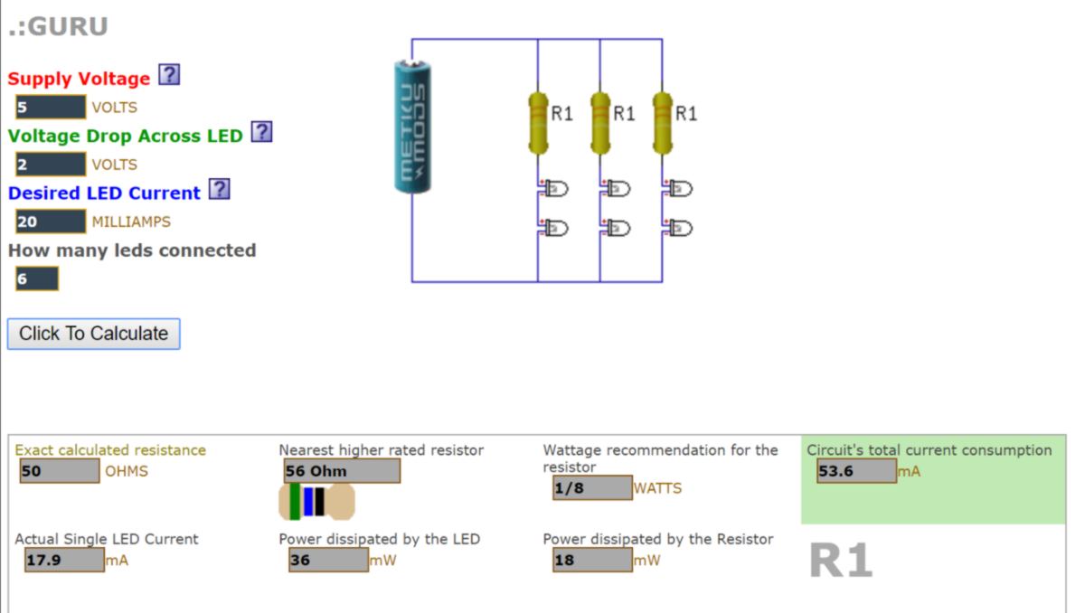
As an extra step I will add 6 yellow LEDs in series which will switch on when motion is detected. I look at the resistance the setup requires with the 2V LEDs I have. Logically I cannot put more than 2 LEDs in serie before voltage in too low to make the LEDs switch on. For this exercise I will plan to set them up in three parallel circuits :
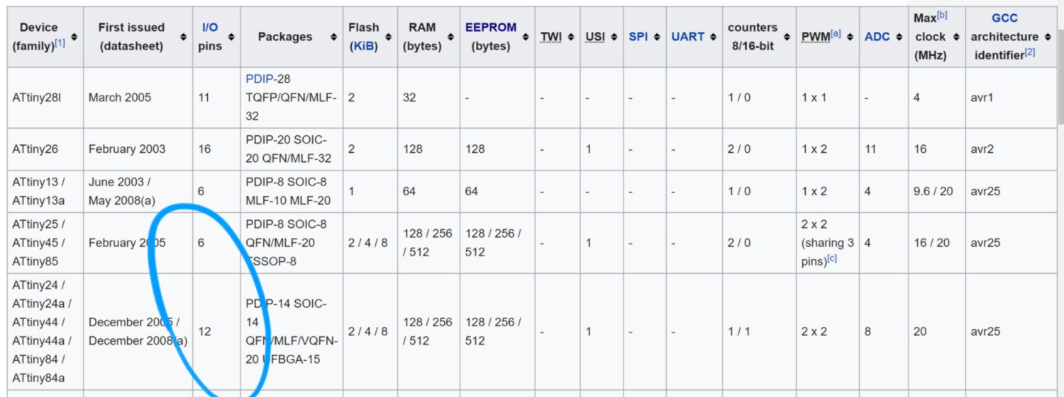
11.04.18 /We were provided with ATtiny44 and 45. In what way do they differ? The question comes up as I look up the design for this sensor on the fab academy schedule webpage . It uses an ATtiny 45.
I look at a summary of the ATtiny45 datasheet and a comparison chart. Basically, the ATinty 45 has less pin that the 44, can have less input/output, but is also cheaper. For this sensor requiring only two pins (1 input, 1 output), this is absolutely fine.
I find out that Arduinos Uno can be used as ISPs :
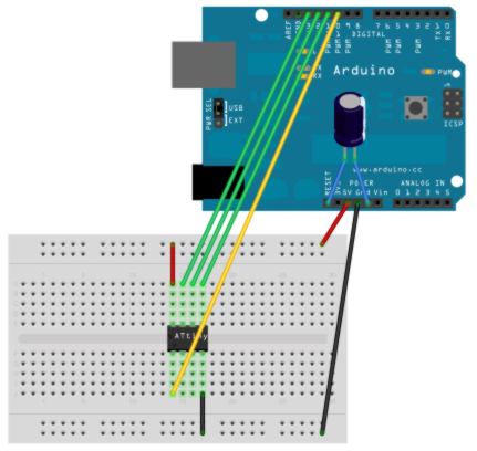
I am curious to try. The idea behind it is to program it on a breadboard, then solder it to a milled board without ISP header, which simplifies the tracing. However the ATtiny45 I have are packaged for PCBs and do not fit on the breadboard:
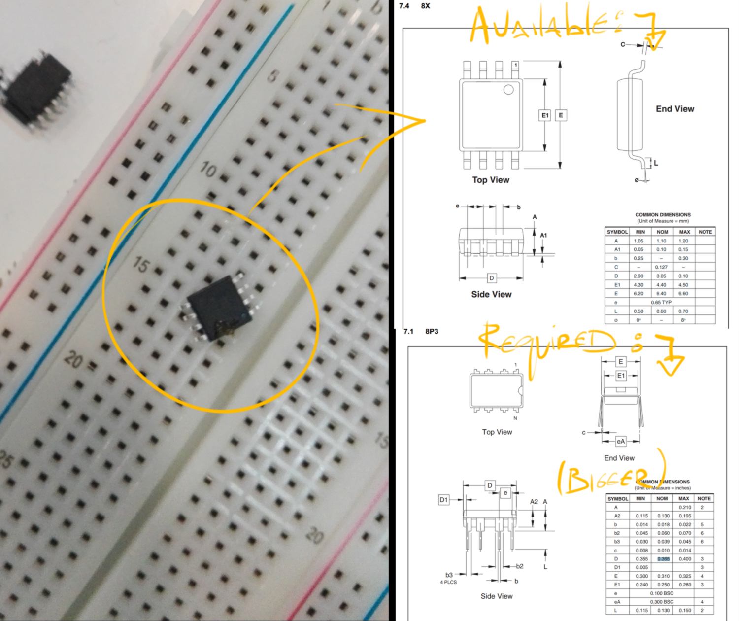
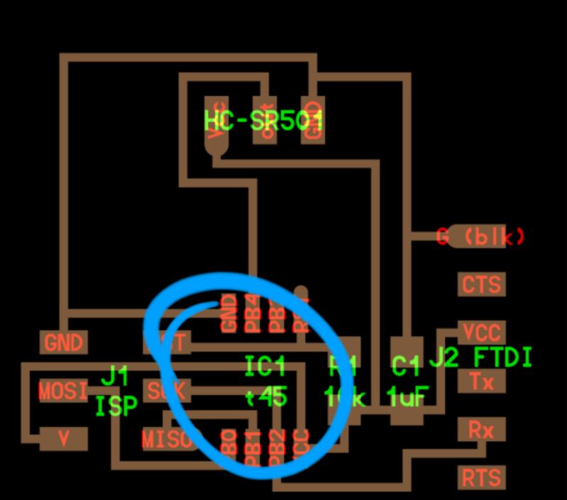
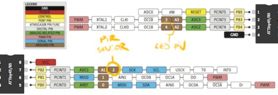
Therefore I will skip this step, fabricate the PCB and program it with the Tiny ISP. I have a look at the board on the Fab Academy webpage and the Arduino and ATtiny pinout diagram to design my PCB :
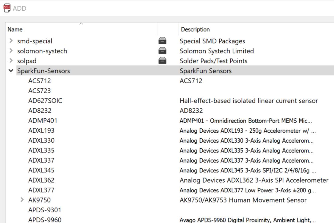
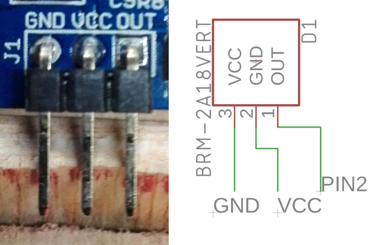
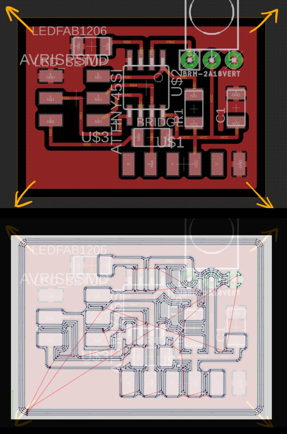
In Eagle, I am missing a component for the Motion Sensor so I download a library from Sparkfun. I correct the connections for the motion sensor :
Out of curiosity and to make the job easier, I attempt to set up copper pours on my design. I set up all ground connections close to the edges of the board to make it more straightforward. However it does not come up as I expected :
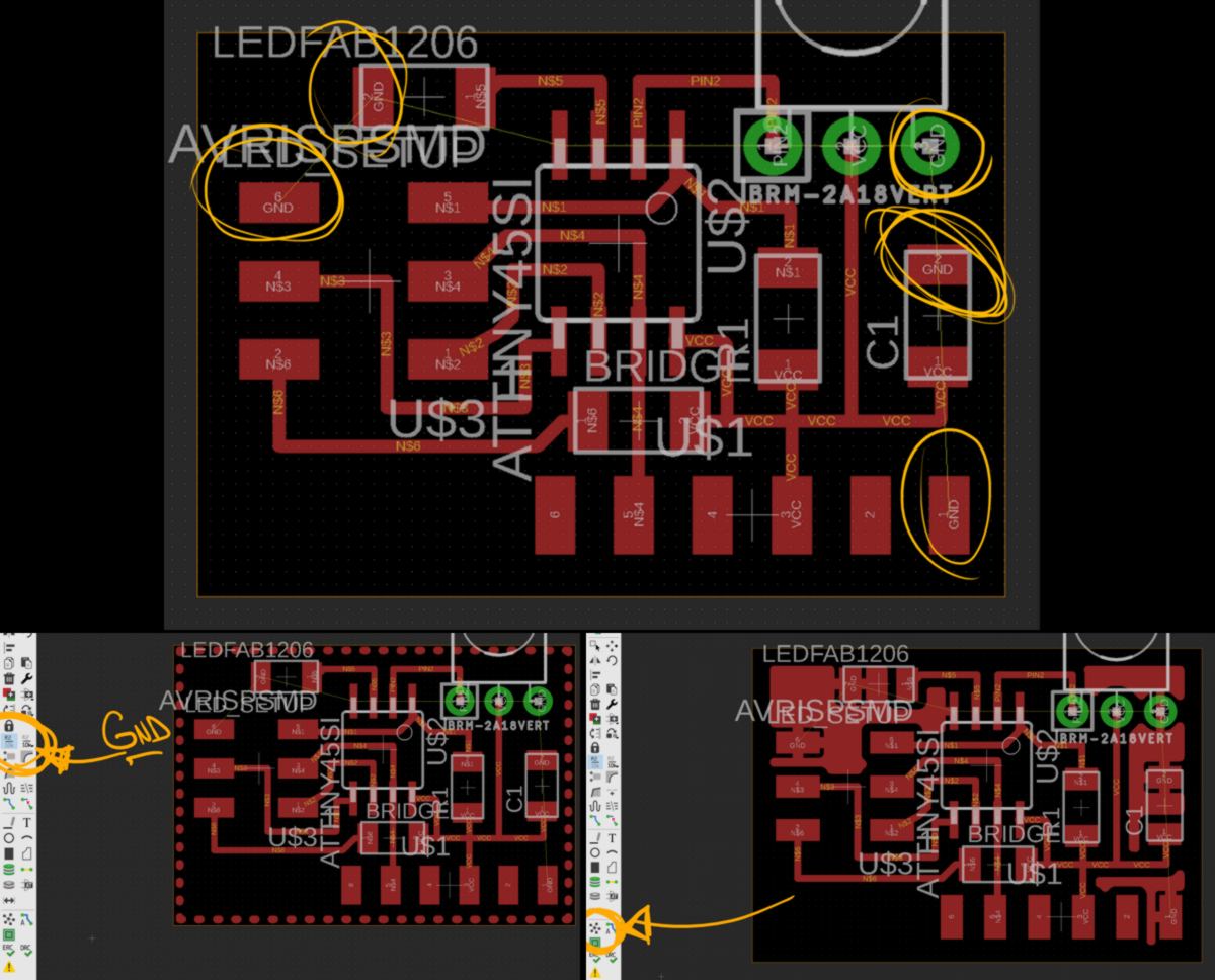
I correct the design manually :
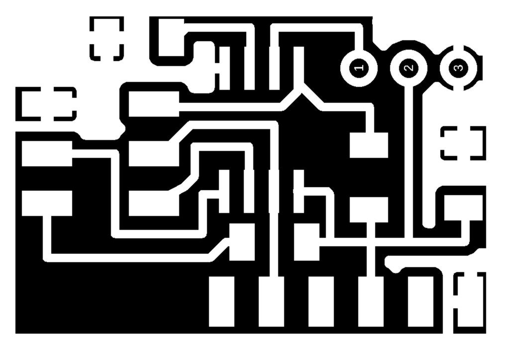
I prepare the g-code in fabModules and notices that the spacing between the copper pours and other traces is insufficient for the 1/64 end mill to fit in separate area correctly :
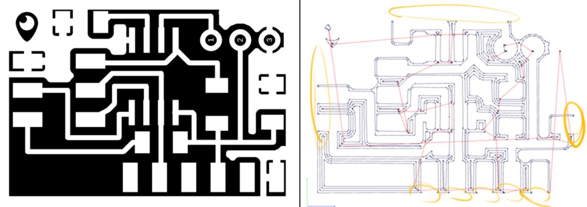
Back into Eagle, I expand the border of the working area, retrace a polygon, name it as GND again, and hit the ratsnest button :
I tried to re-trace the polygon with a thinner route as recommended in the Help section but the margin does not change. I keep this mystery unsolved for now.
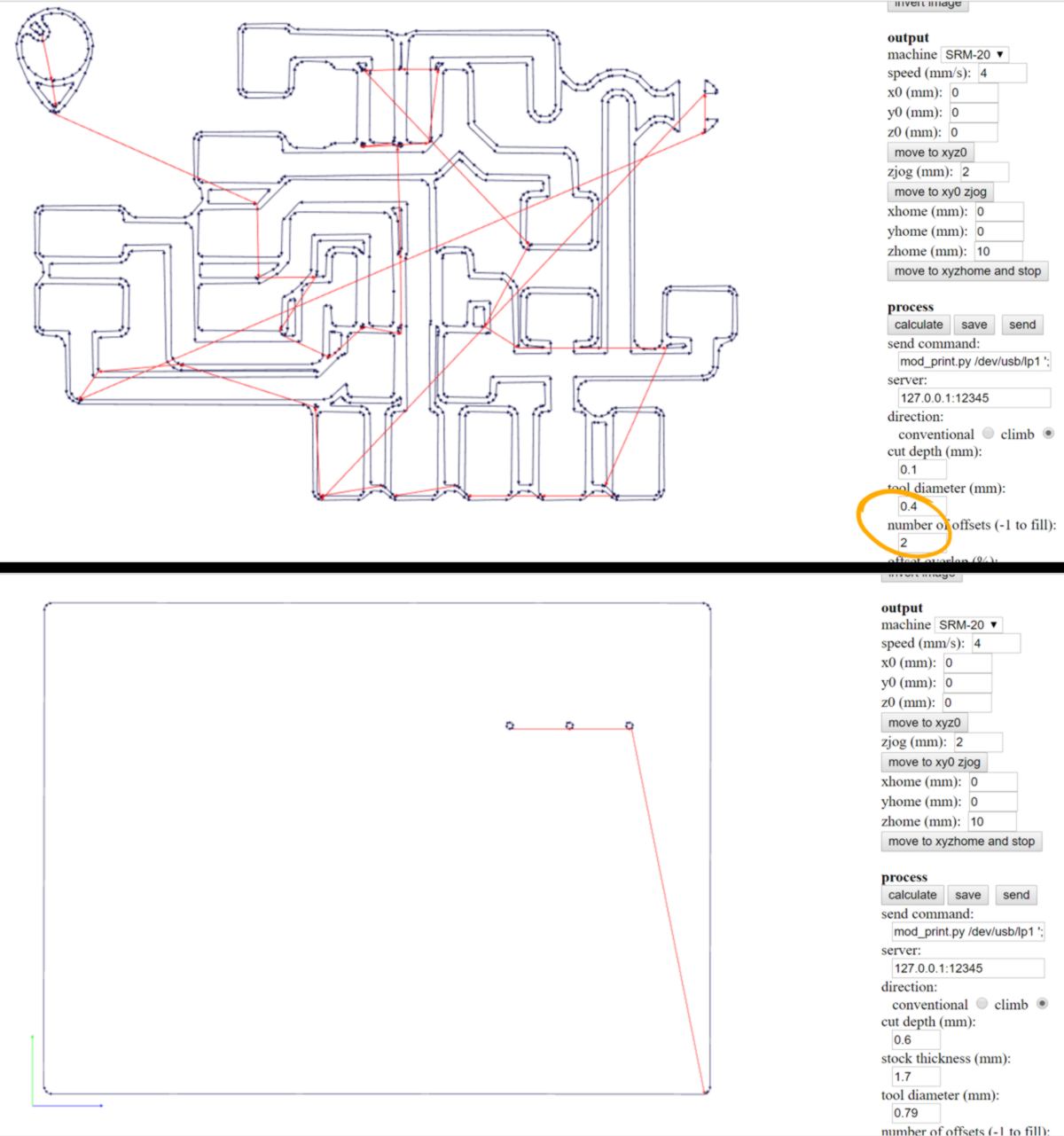
12.04.18 I mill and stuff my board using the SMR-20, a 1/64 and a1/32 end mill :
When trying to load the program on my board, I get an error (with both USBTiny ISP and MK2 ISP). The ISP used is not recognised by my computer.
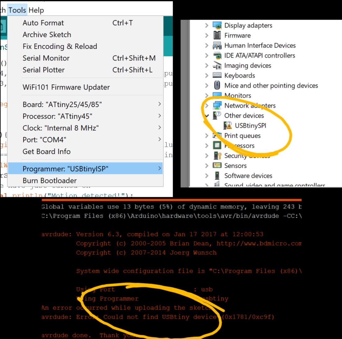
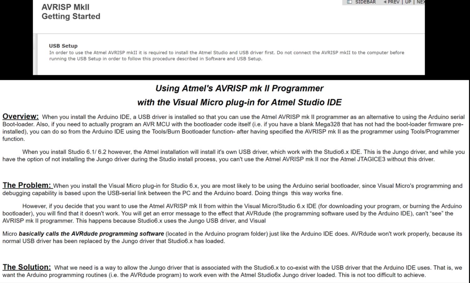
What I have to do is set up Amtel and make change on the way Arduino handles its bootload :
I will do that later. For now I want to know whether my board functions correctly without adding an extra layer of complexity. I go use the Linux computer at the lab. However Ubuntu does not start properly, Arduino needs to be reinstalled, and the sotware must be launched in admin mode. After a few minutes fighting with Ubuntu, we burn the bootloader and load the code successfully :