
Attending the Fab Academy in Barcelona, I document each week of intense learning as I come across new digital fabrication techniques.
This documentation is as much a report of what I do as a reflection on why I do so, and will hopefully guide me back to Oceania to spread and make good use of the knowledge gathered along the path.
--- summary of the assignment ---
objective :
Write an application that interfaces with an input and/or output device - that you made -, comparing as many tool options as possible.
what I did :
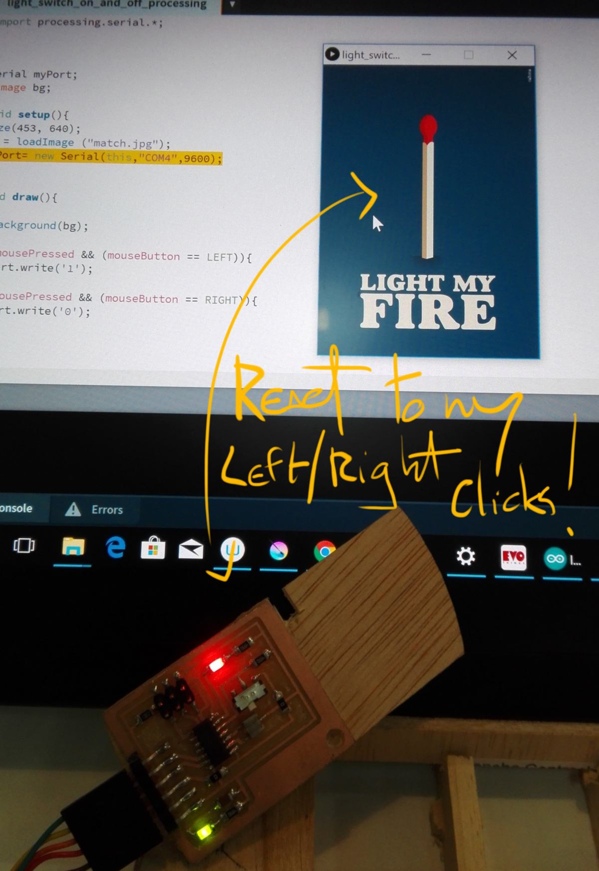
I built an interface with Processing, using my computer as an output to switch an LED on and off ( see week 12). I also built an interface with p5.js, using a potentiometer to control an ellipse on screen. I finally designed a board with a joystick to do something similar in Processing.
download :
Learning outcomes :
30.04.18 / I will attempt to write on an ATMEGA 328 EEPROM . I look for some documentation. Again the documentation on the Arduino website is a little cryptic so I have a look at a video which offers a more friendly explanation. However the code offered is built from a precedent tutorial, so I look for some more documentation, then finally find a video describing the very basics.
The issue is that the code that is used in the sketch I found is somehow different:
Looking at shedding some light on it, I look at some documentation online :
I am not much more RFID savyy, I am lacking the basic programing knowledge to grasp how this piece of code works. What I initially intended to do was to write the name and IUD number of the user in a single sheet, then automatically export the sheet and its data to all learning kits. But for now I have no idea what the EEPROM looks like. I need to have a look at it myself.
I set up an microcontroller with an RFID card and find some code to read what is currently in the EEPROM :
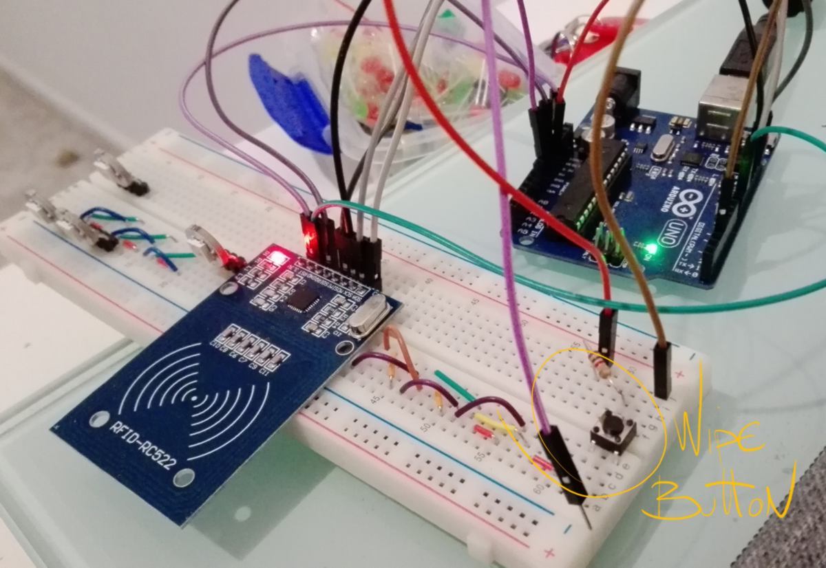
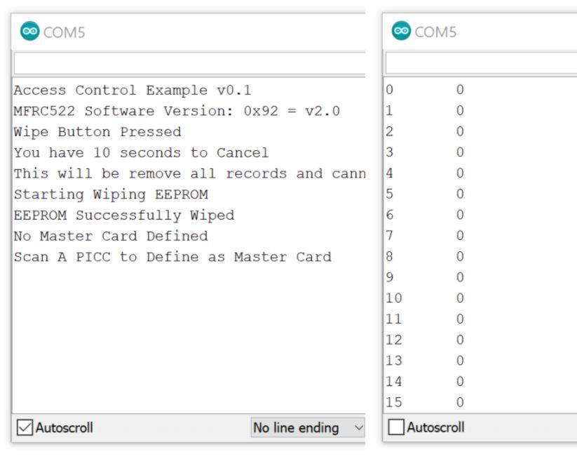
I revert back to the doorlocking system and wipe the EEPROM with the wipe button, then check what is on the EEPROM :
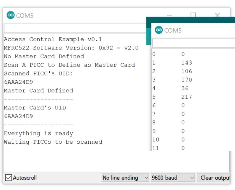
I record a master card, then another card, and an extra couple of times :
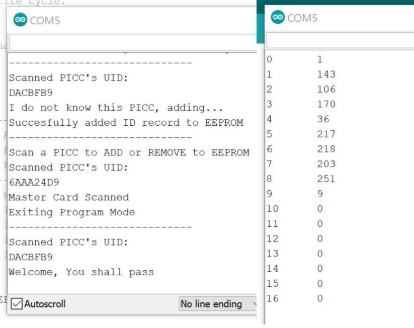
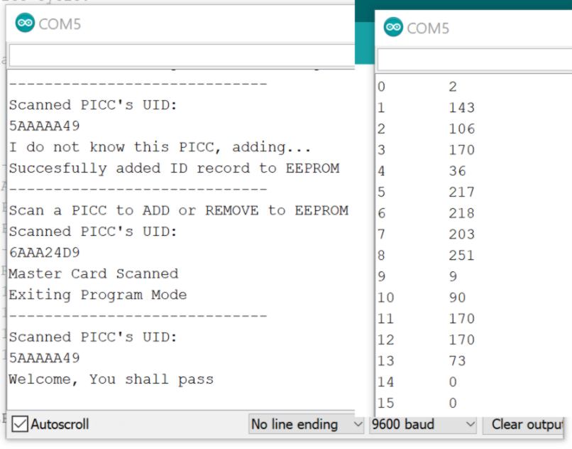
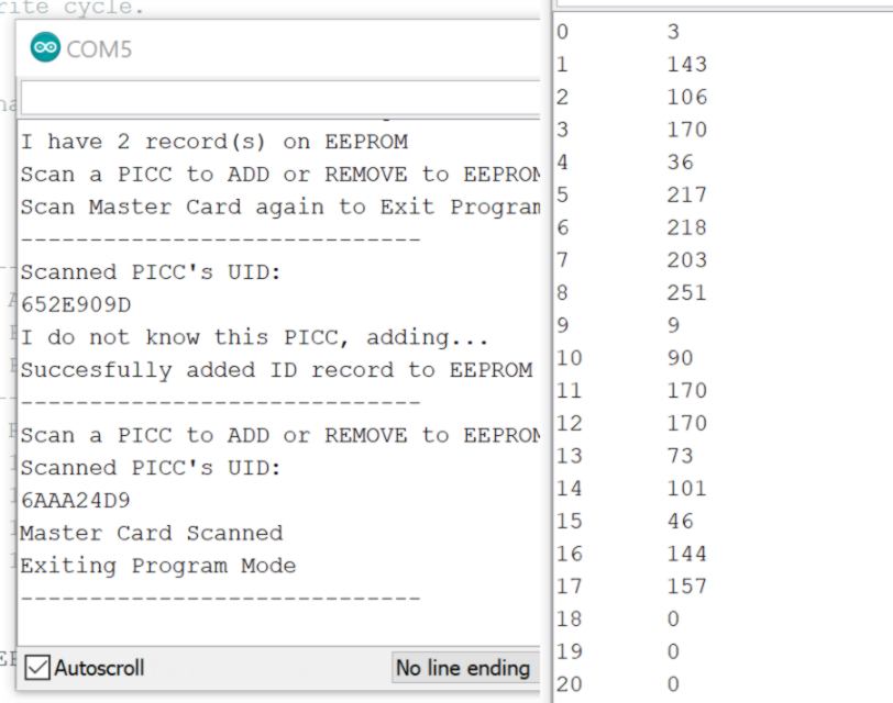
Now I use the "Dump info" code to read the IUD of each tag, and compare it with the result found :
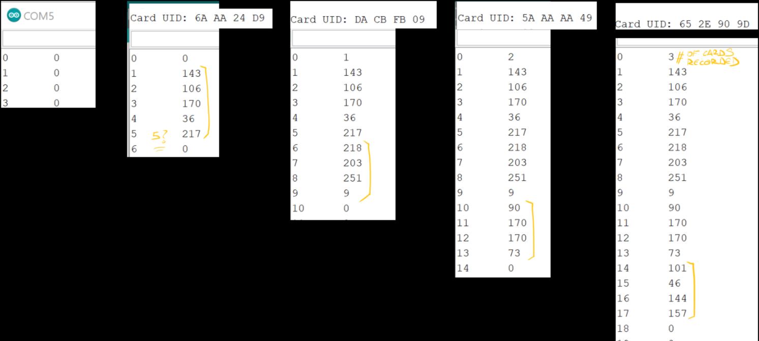
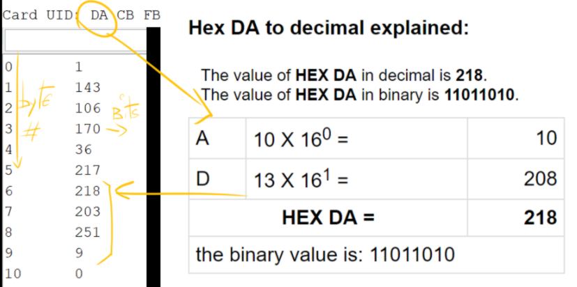
These are hexadecimal numbers of the RFID UID (I just learned about hexadecimal reading about binary today, how convenient) :
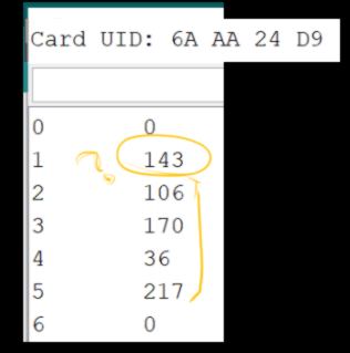
the Number 143 is defined as the "magic number" in this code ( I thought is was 42, whatever) to find the mastercard (a lot of complex mathematical explanations is available, out of curiosity I should send a letter to Miguel one day), If byte 1 holds 143, it means there is a mastercard, and that is defined when the mastercard is swiped, which is why the mastercard holds 5 bytes rather than 4 :
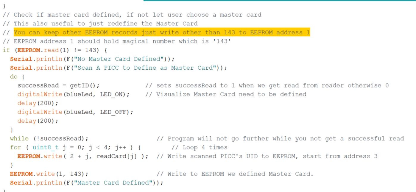
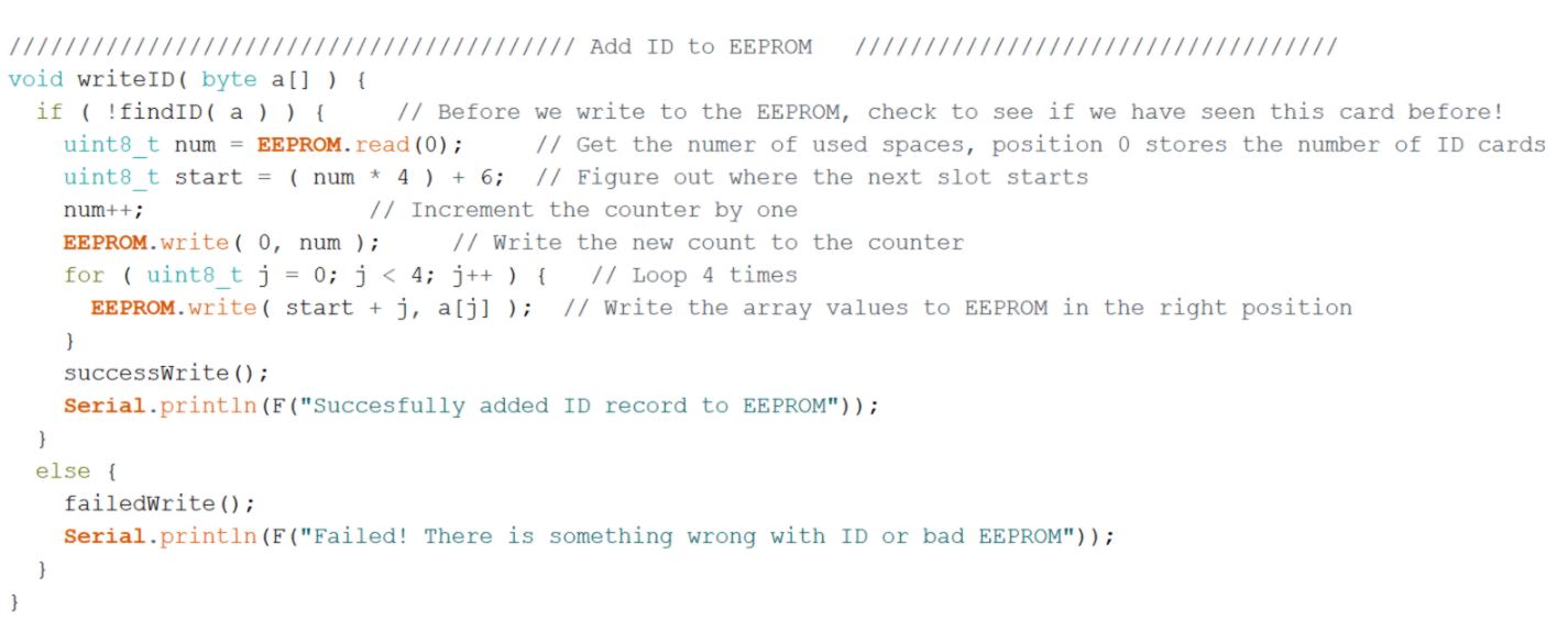
Now, knowing all that stuff, can I write directly on the EEPROM so that the RFID reader gives access to a card it has not scanned? I am going to wipe everything on the EEPROM but the master card, and attempt to write on the EEPROM the IUD of another card :
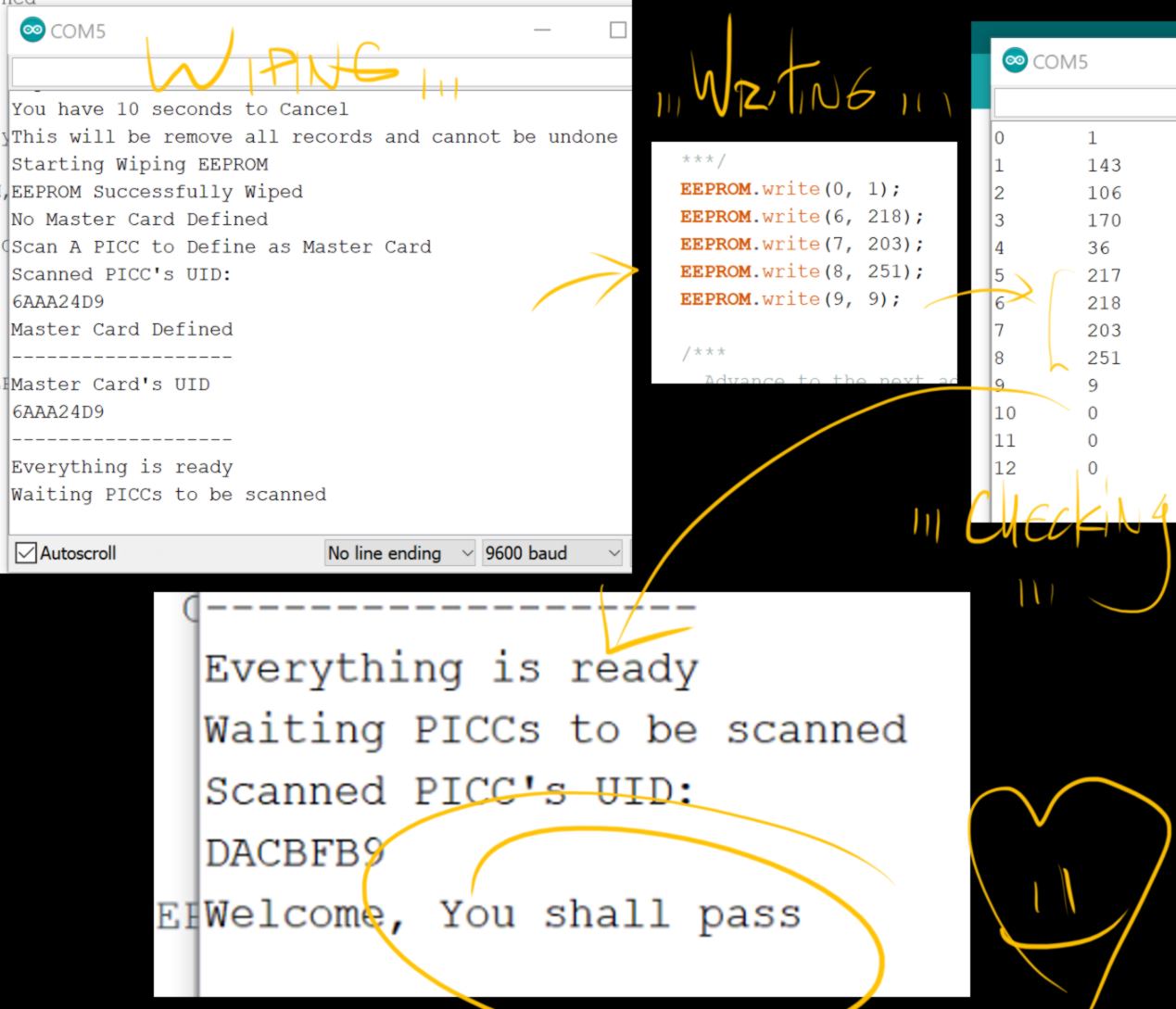
It is successful. I now know how to get rid of the RFID reader and write on the EEPROM directly via the interface.
01.05.18 /What about Mozilla Open Badges? I need an online system to track users knowledge, so I look at an existing system :

I read a tutorial about creating badges. I create a backpack for myself and earn my first badge. I learn it can be shared on social media, and contains extra data. Ok, interesting, but not relevant technically just yet. It is an extra step which would come handy for users to go to other labs with similar systems so their skills are recognised. the creation of badges can be embeeded in the interface later on.
I look at creating a sheet that triggers the EEPROM to be updated. Apparently Google form and Sheet can do that. I also look at Libre Office but cannot find tutorials.
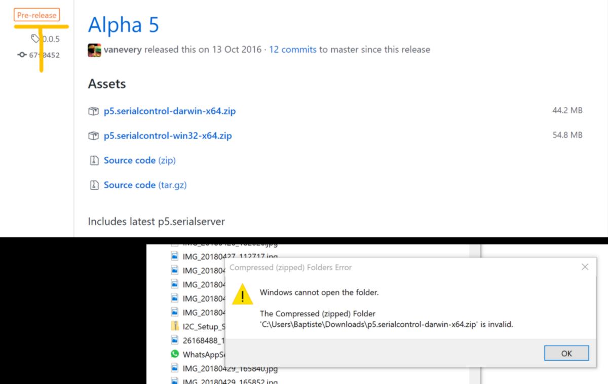
Rather than bying a webduino smart, I would like to use the ESP8266 I have right here, so I find a more relevant tutorial, and look at Google API (what a great speaker this Wesley Chun).But, hold on, wasn't I supposed to used the bot library or the serial library from p5.js?
I wish to stick to the p5.serialPort for now, but I have an error message as I intent to install the.zip file:
I move on to P5.bots and bump across other issues, the basic one is that there is a lot going on that I have not approached (setting up web server) and broken links. Frankly I have a little less than a day before the new week starts so I would rather skip as many hurldes as possible. Lets see what Processing can do to ease the pain. Processing has a serial library that can be used.
I want to write the IUD value in processing, then upload them to the EEPROM. As usual I have trouble finding the right tutorial, although this one and that one are useful. The control IP5 library is also available. It seems so complex to create a textbox where in HTML it is so simple. AM I looking in the right direction?
Rather than wasting more time looking for the right tutorial, I am going to learn about coding with p5.js with Dan. At least I will learn something today!

Oh wow. It has been a beautiful flight across the p5 cloud9. So, many many videos later, I look for tutorials for p5 and serial communication with microcontrollers and find in a minute this one and this one, both very very comprehensive. The video is actually useful, however I have error message about the "println" function, which is part of the p5.js library. Somehow it does not seem to be taken into account.
02.05.18 /I attempt to connect my arduino to a p5 sketch again. I get the same error as yesterday :
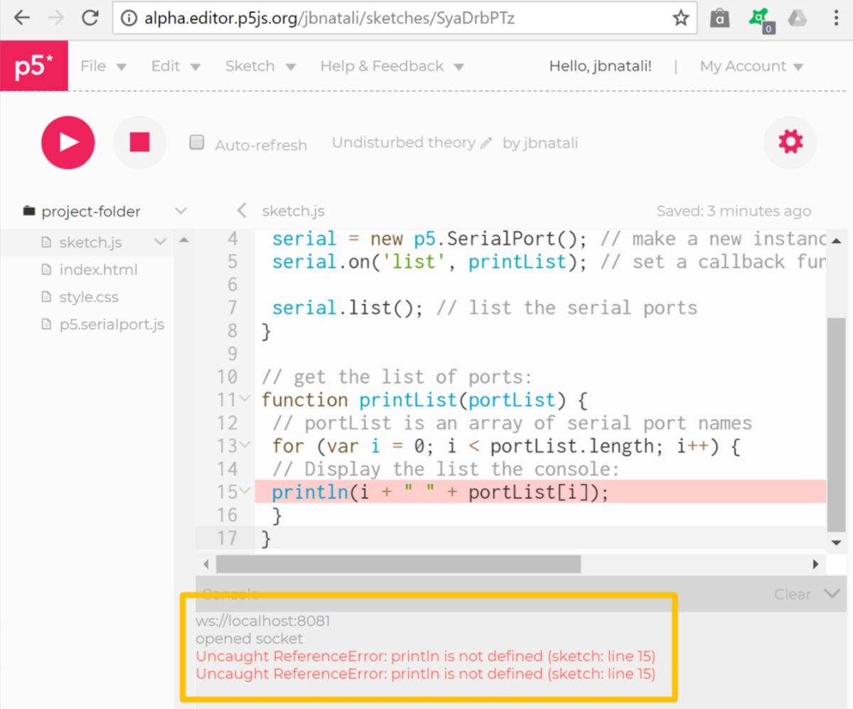
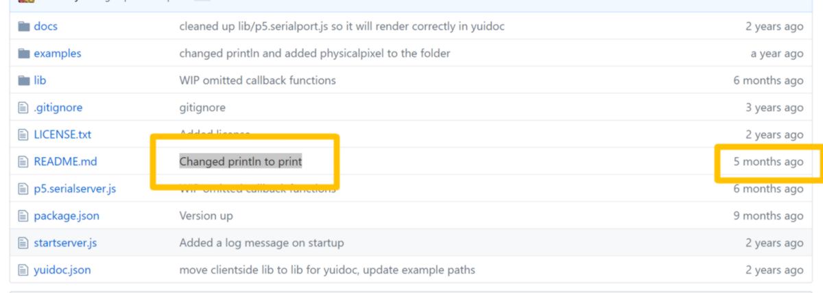
Looking at the Github database, I see that "Println" was deleted and modified two months after the video was shot. Now the library uses "print":
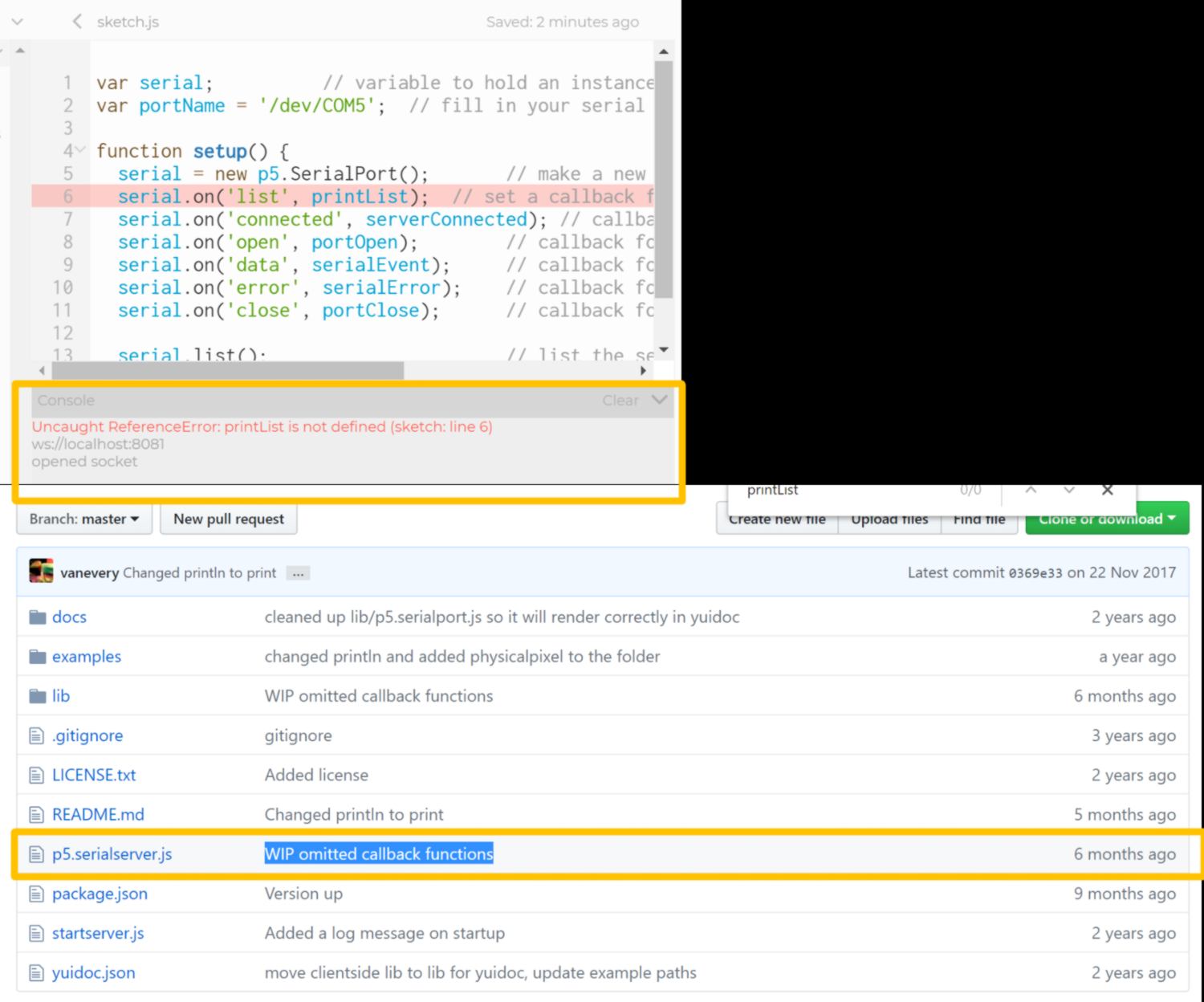
I replace one by the other, which provides me with a list of port, then move on to the next sketch - the one that should give me a visual feedback of the potentiometer. However I get extra error messages. All callback function do not seem to be defined. I cannot tell whether it is because of a modification on the Github 6 months ago :
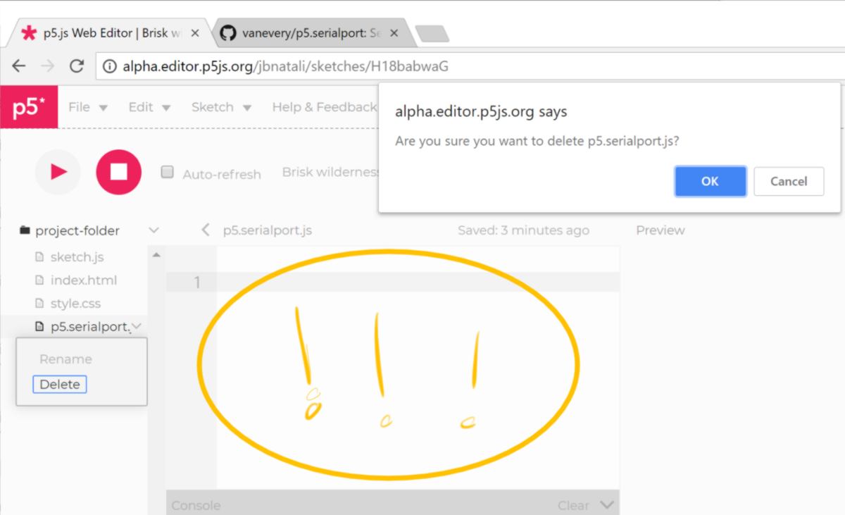
It seems like the whole library is missing. I download "p5.serialport.js" again, this time directly from the github repository (rather than using the link provided on the webpage) and try again. When deleting the former "p5.serialport.js", I realise the whole file is actually empty! There seems to be a bug in the online editor, which does only create a file with the correct name but does not populate it :
I copy/paste the content of "p5.serialport.js" by hand and run the sketch again, but it comes to the same conclusion. I search for these function in "p5.serialport.js" and realise they have been commented or deleted - and some of them are commented as not working in the online editor :

I look into the content of former versions uploaded before the video, and replace the one I use with one of them, with no success. I will move on to next week assignment, until I get some help from my instructor or another student tomorrow.
03.05.18 / debugging the issue with one of my instructor takes most of our afternoon. After following the tutorial online without success, we attempt to do the same using the processing IDE in p5.js mode, but it fails as well. We end up downloading the examples folder from Github and I run them through Atom, using a local server, with p5.serial control switched on in the background:
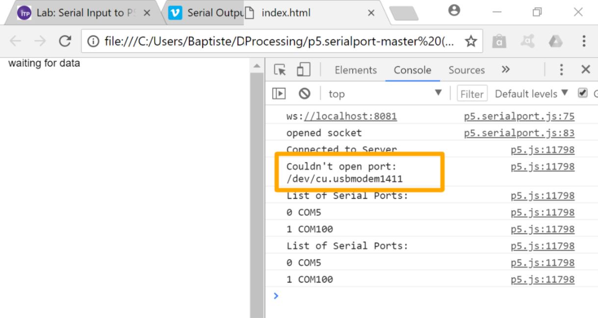
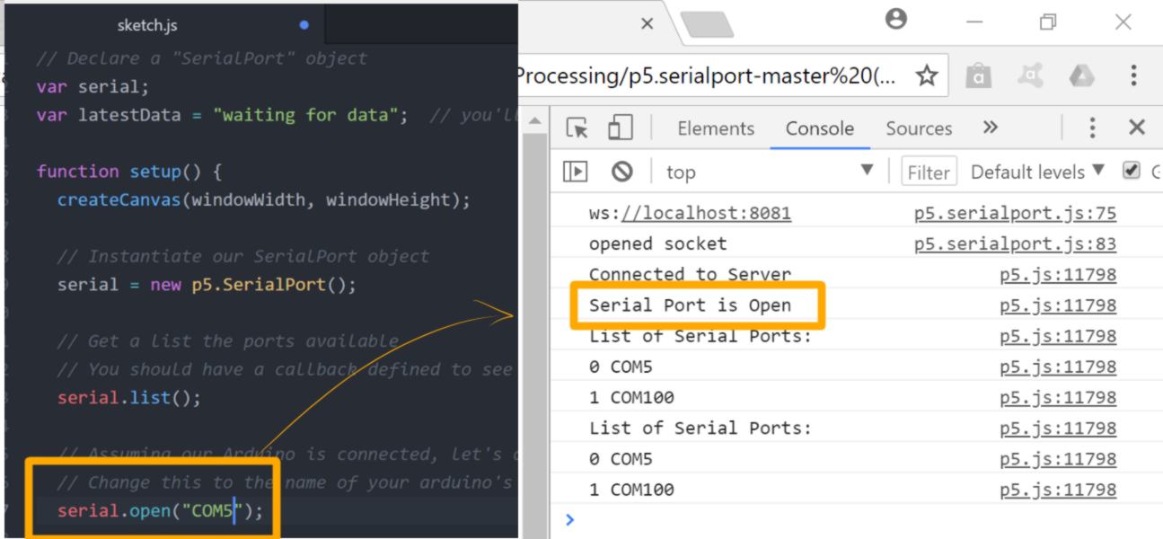
A little issue occurs at first, but we provide the correct port name to the sketch:
It seems almost too good to be true. Plugging my arduino in, with a potentiometer sending bytes between 0 and 255, I load another example providing feedback on serial data received :
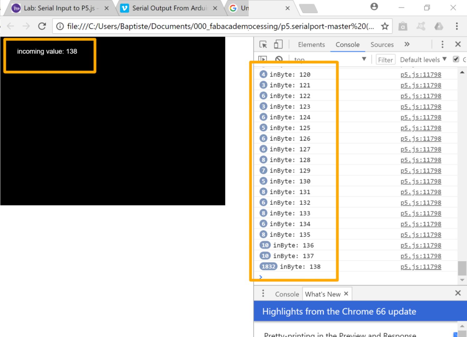
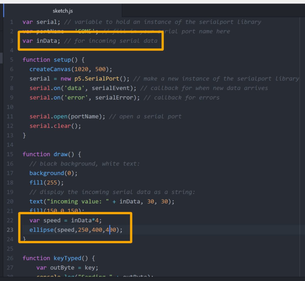
Data is transmitted correctly. Finally! For the sake of putting into practice a few things I learned with Dan, I write a sketch where the position of a shape on the x axis is controlled by a variable modified according to the input coming fro the potentiometer :
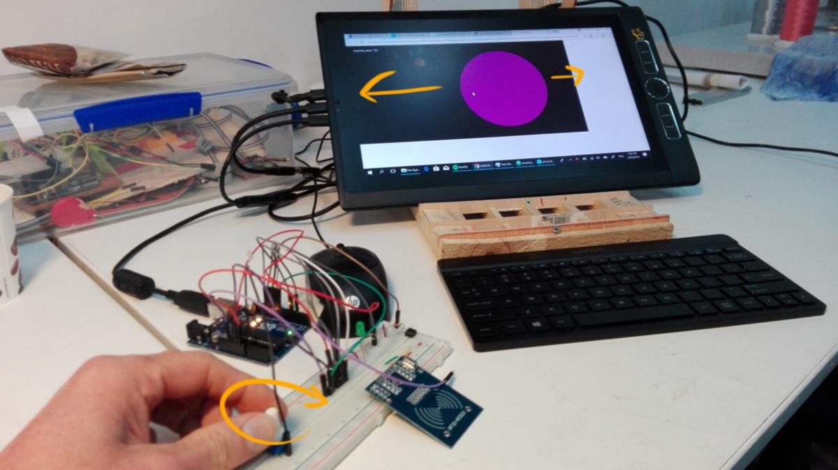
This is unleashing tons of possibilities for interaction - I am looking forward to design the interface for my final project. This is however running on a local server, so it is not quite on the internet yet, but it enables me to develop interfaces that will be.
Now I would like to understand : why are the examples working, and my prior codes were not? Well, turns out the p5.serialserver.js on the github and the p5.serialserver.js to be downloaded from the tutorial webpage are completely different. A simple way to check it is to chekc the number of lines : 268 vs 767!
It seems like the - incorrect - version which was available on the website was the prototype upon which the new file was based. It seems full of - commented - examples to be copied/pasted as main script. It is way beyond my understanding, I put it here if someone could shed some light on it. I add a short message as comment on the Vimeo to avoid other people from struggling. I also hope the comment will get some feedback and things will be clarified in the tutorial.
I won't have the time this week to finish my interface for my final project but I now have all the tools setup to make it work. I have also learned a great deal about Github in the process, and even more about p5.js.
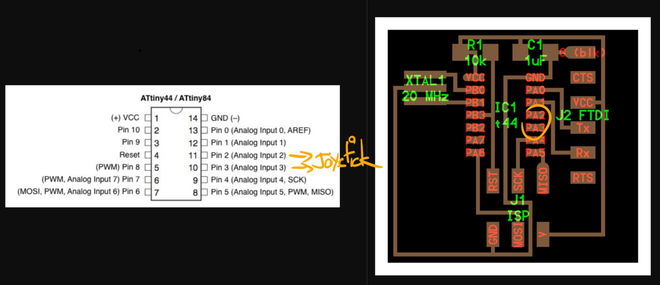
27.05.18 /Last Minute Addition : This tiny project is calling for a controller, a board with two potentiometers to control motion of the "tip" of the pen on the x and y axis, as well as a button to reset the canvas. Well, this is exactly what a two axis joystick is. Some of them come with an additional button. About microcontrollers, the ATtiny 45 offers up to three pins for analog input:
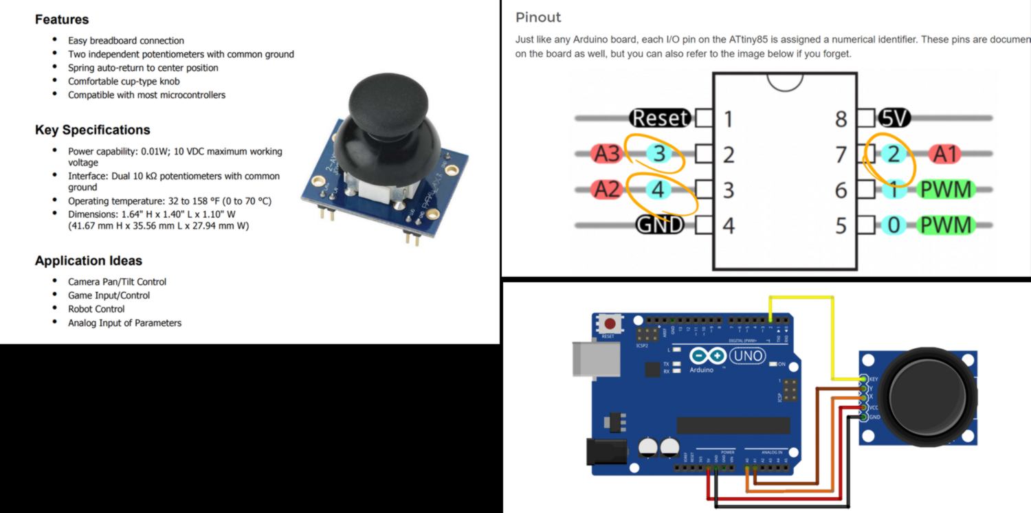
I begin to set up the design in Eagle , connect the potentiometers, set up an extra button with a pull-down resistor. Then I realise that, reading this tutorial, the potentiometers are using the same pins as the RX/Tx connections, which are required for serial connection. I will upgrade to the ATtiny44:
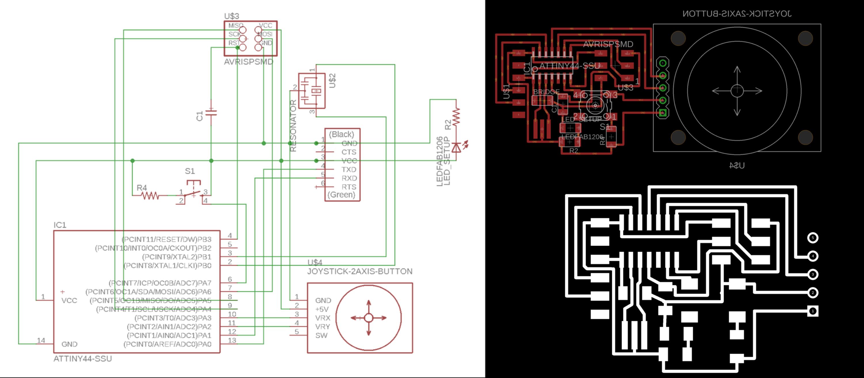
I used the hello board as an inspiration and add the components required : a joystick and a switch with a pull-down resistor :
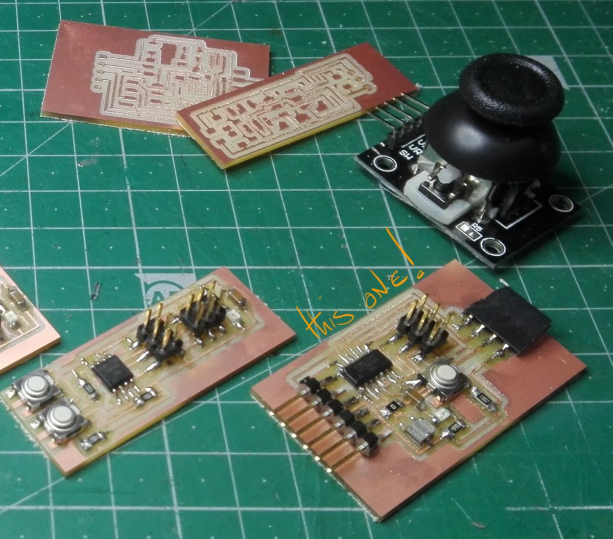
30.05.18 /Last Minute Addition : I have milled, stuffed and bootloaded the board two days ago. The joystick is meant to come on top of it like a shield :
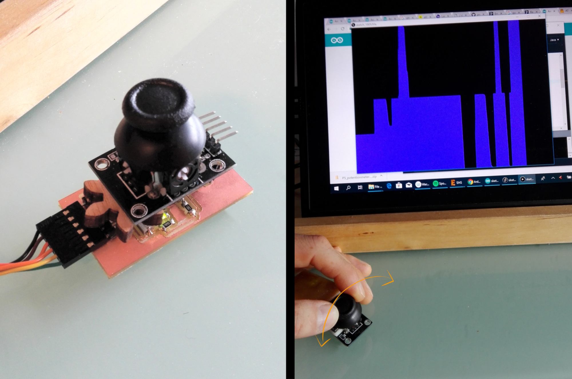
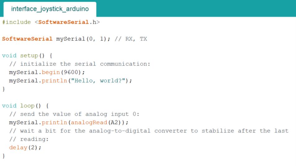
For the purpose of this assignment I will only use one of the two potentiometers, write a code for the board using the software serial library and a code for processing to show a graph of the data received inspired from this example.
It works the following way : On one side, the arduino sends the value of the potentiometer via serial to the computer :
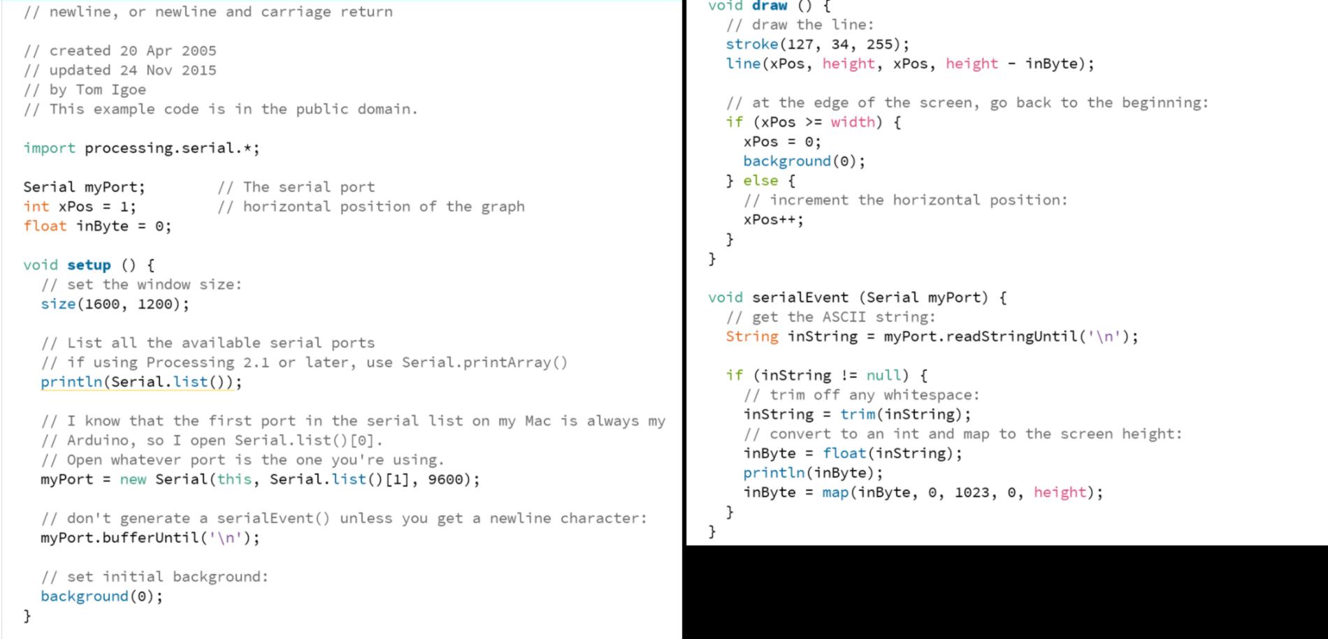
On the receiving end, Processing picks up this value, which is converted and mapped, the used as a height to draw a vertical line (coded as a serial event at the bottom). The origin on the x-axis of this line constantly moves forward, until it reaches the value of the width of the screen, where it goes back to the left of the screen.
This board works well as an input for my interface. I will keep it on the side as a potential controller for another project.