
Attending the Fab Academy in Barcelona, I document each week of intense learning as I come across new digital fabrication techniques.
This documentation is as much a report of what I do as a reflection on why I do so, and will hopefully guide me back to Oceania to spread and make good use of the knowledge gathered along the path.
16.05.18 / I come back to Barcelona after a week away and discover with delight that my team has been developing the machine smoothly. When stepping into the room I see them playing with it, fully operational. Not only it is impressive effort wise, but it also looks good! The iris has an appealing design, the motion is smooth, and I am looking forward to bring it to the Makerfaire in June! The only hiccups of the design is the sound : the stepper motor driving the belt makes an awfully loud noise!
I am looking forward to document it all and update the website, so I can send it to some friends in New Zealand for testing purposes. I gather some documentation from Javi, both on his weekly updates and on the Google drive previously set up, and populate two new HTLM webpages, proofreading texts and editing pictures as I add new elements in. Paragraphs are spread across the different pages, titles and sub-titles are added, the white background is changed for a grey-ish color, less brutal to the eye, and some videos are uploaded to Youtube so I do not have to host them on Gitlab, making the folder lighter.
I keep on refering to the paper kit website to add element using the correct class name, round the corners of each picture, select the right font size and type and so on.
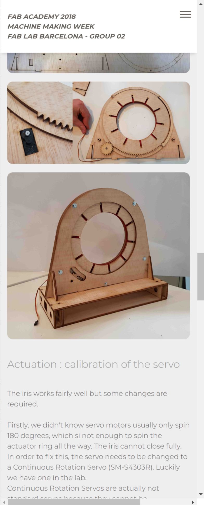
I also update many details on the main page : description of each team member, images, writing the introduction, proofreading the rest of the text, and adding relevant link in the footer of the webpage. I finally upload my own part of the website - website design - and send a call for all other members get some documentation together so I can fill some gaps.
It is also the perfect day to catch up on the recitation and the lesson I missed. I actually like approaching my assignment with the technical implication of machine making, from the actuation to the software interface, having an understanding of concepts such as software objects, structural loops, error budgets, open-loop and closed-loop, bang-bang and PID, interpreters vs real-time networks and so on.
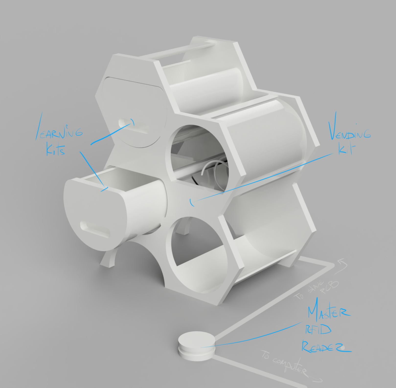
I take a minute to update my final project :
18.05.18 / Making things that matter, is it possible in a week? I listen to the recitation about "making things that matter" from last week as an inspirational talk. The machine my team has developed is fully operational and I don't see how to improve it. I am looking for another machine to make.
To do so I have the advantage to be able select a machine which has been made last week by fab academy students. I browse through the local fab academy websites of labs. I am particularly interested in two machines :
For both project the documentation is not finished. Although I will politely ask for the design, I am unsure I will be able to get them on time.
The second machine is particularly useful in the development of my final project. I will go ahead and explore this option.
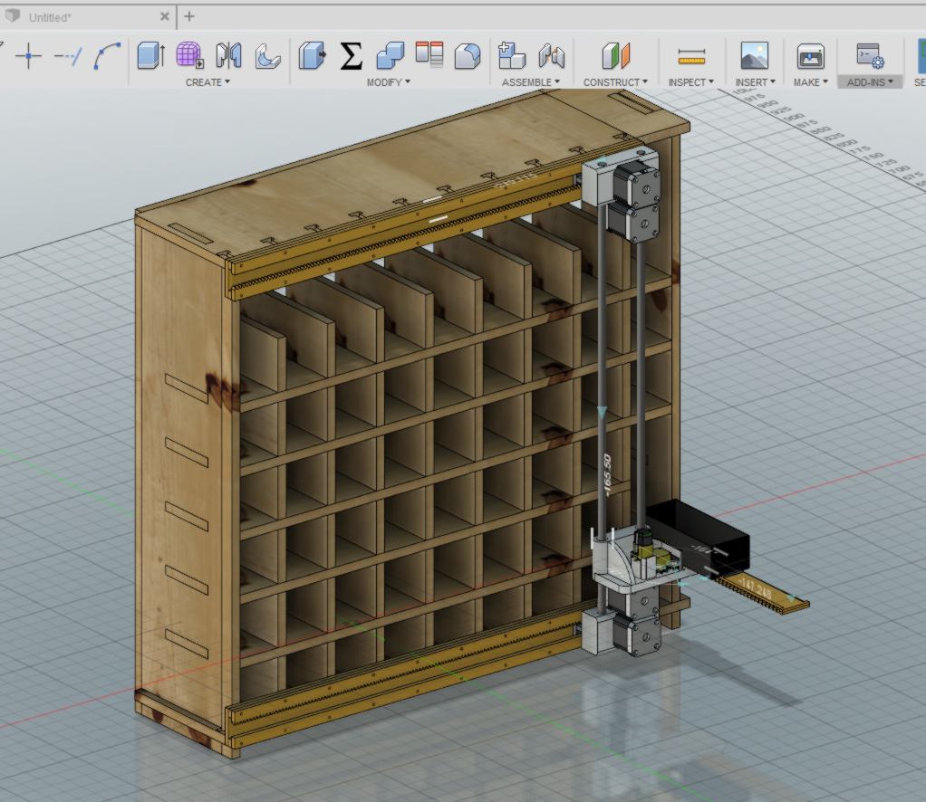
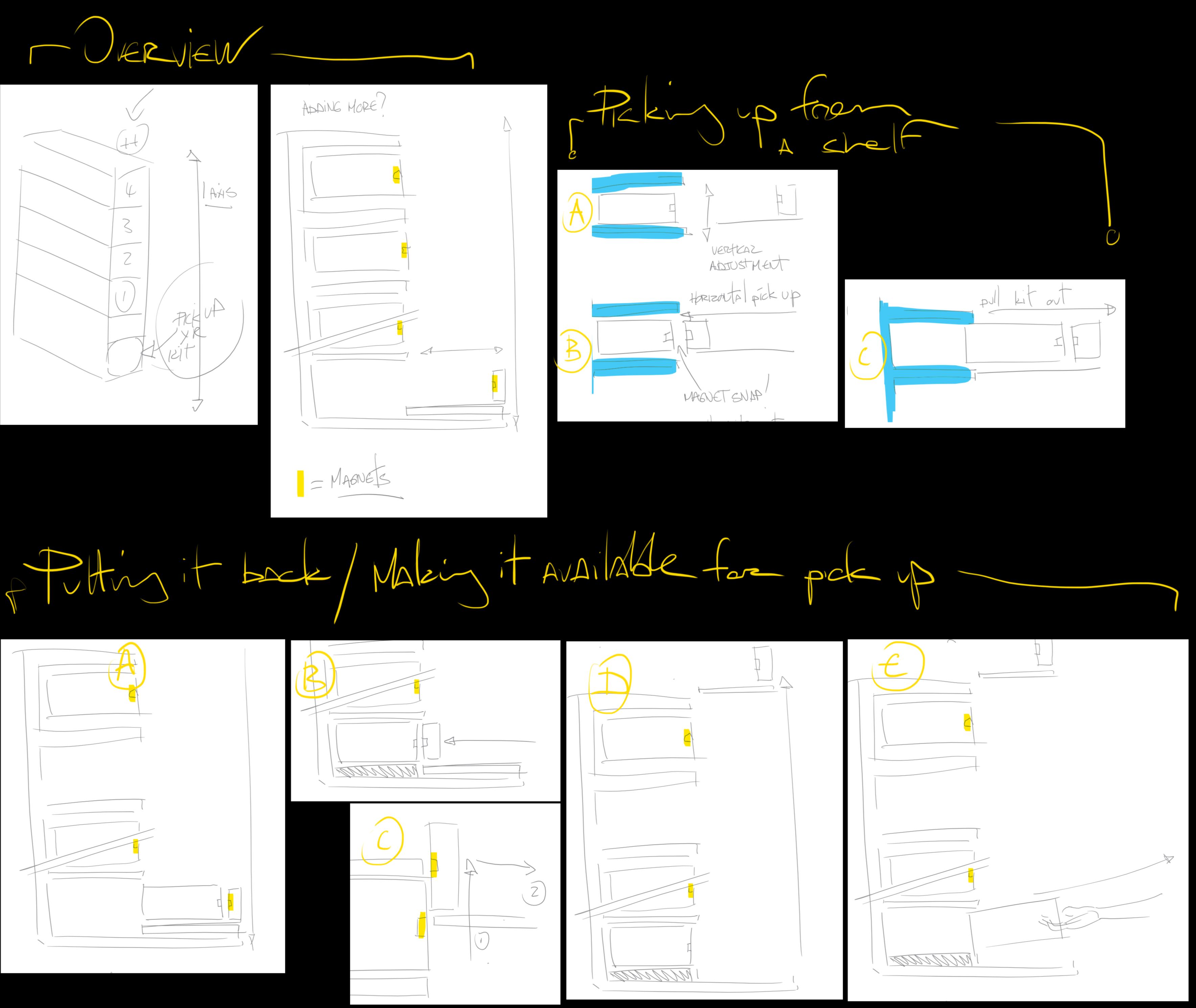
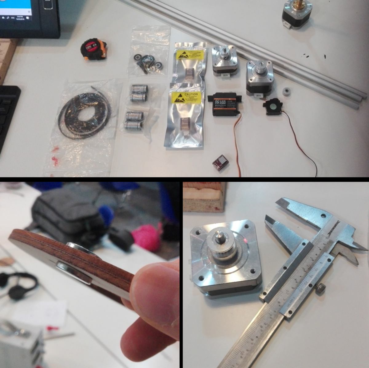
I head to the lab to find the pieces required, but there is not much left after the machine making week. I am missing the rods, which I order. I source two stepper motors (one per axis), bearings, drivers, a belt, some magnets and miscellaneous items. I start measuring some of them to integrate them to the digital design.
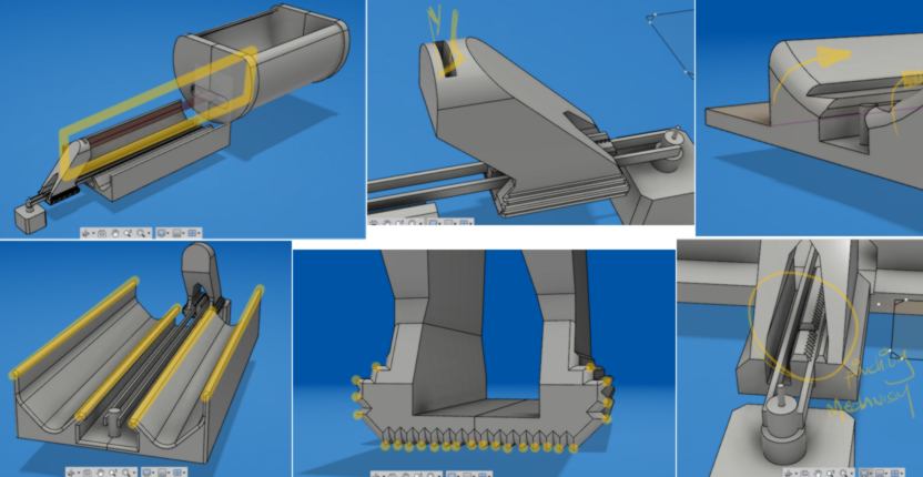
Until the pieces ordered arrive, I am going to design the push-pull mechanism:
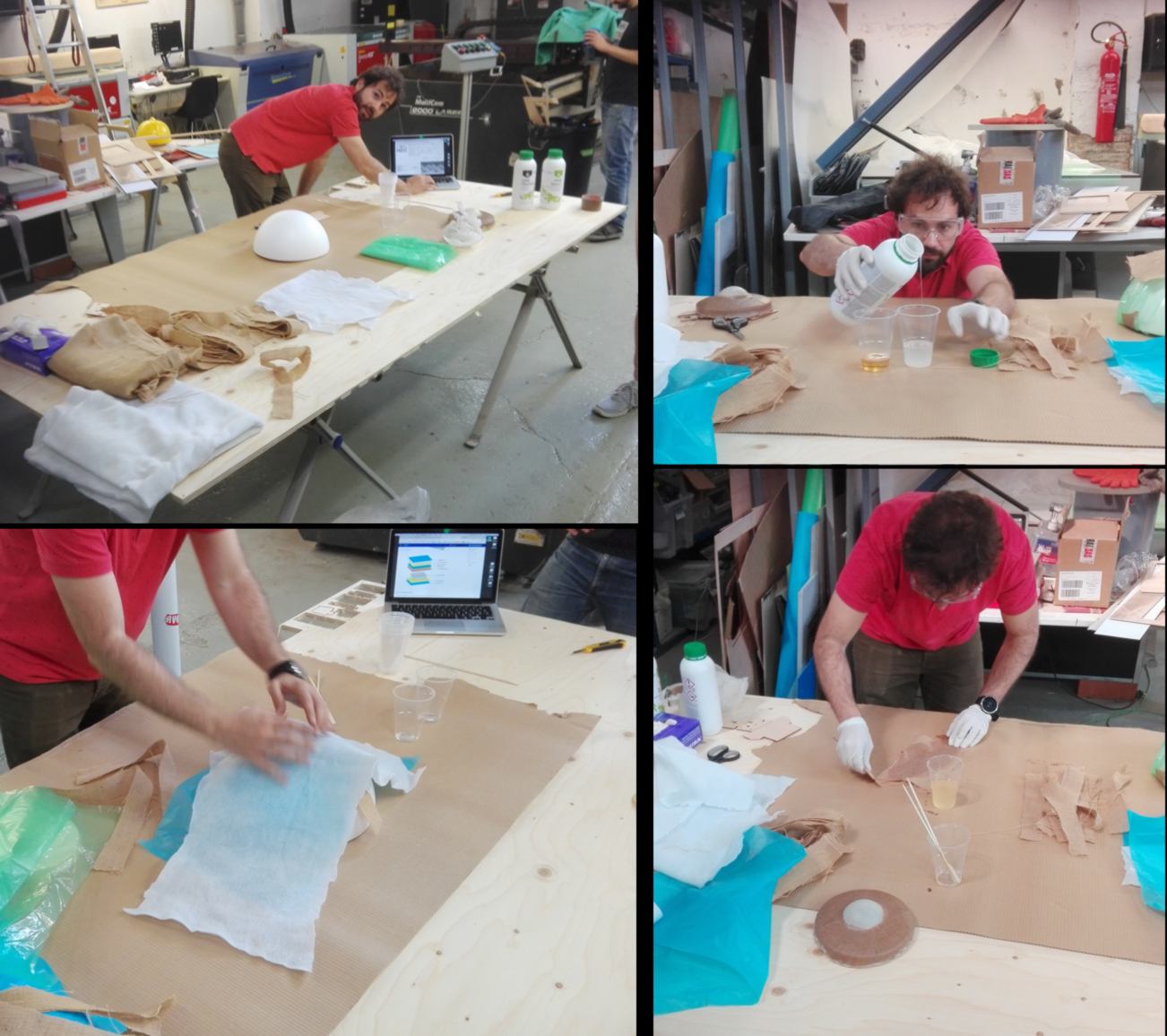
In between two design sessions, I swing by the workshop where one of our instructor offers a workshop on composite material. I learn about the different layers required to suck the extra epoxy out and protect the vacuum press, general safety procedures around handling epoxy, and other related skills.

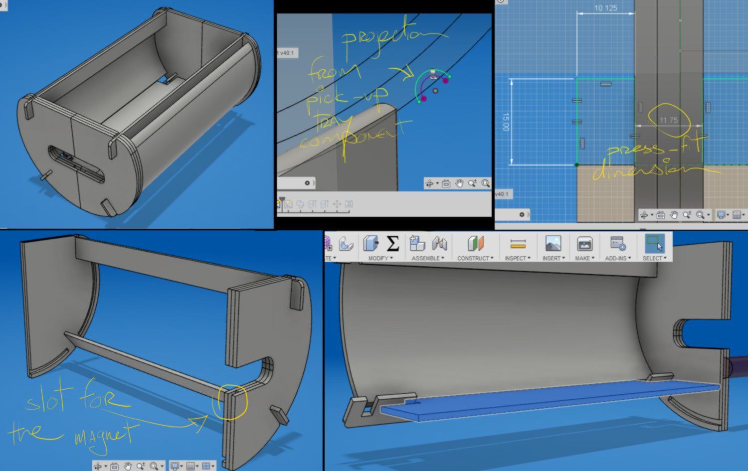
19.05.18 / I carry on with the design. I adapt the drawer to make it match the design of the pick up machine, and finalise the press-fit structure around it. I design it so I will be able to laser cut it with a 4mm sheet of plywood. I found that laser-cutting was much faster than milling.
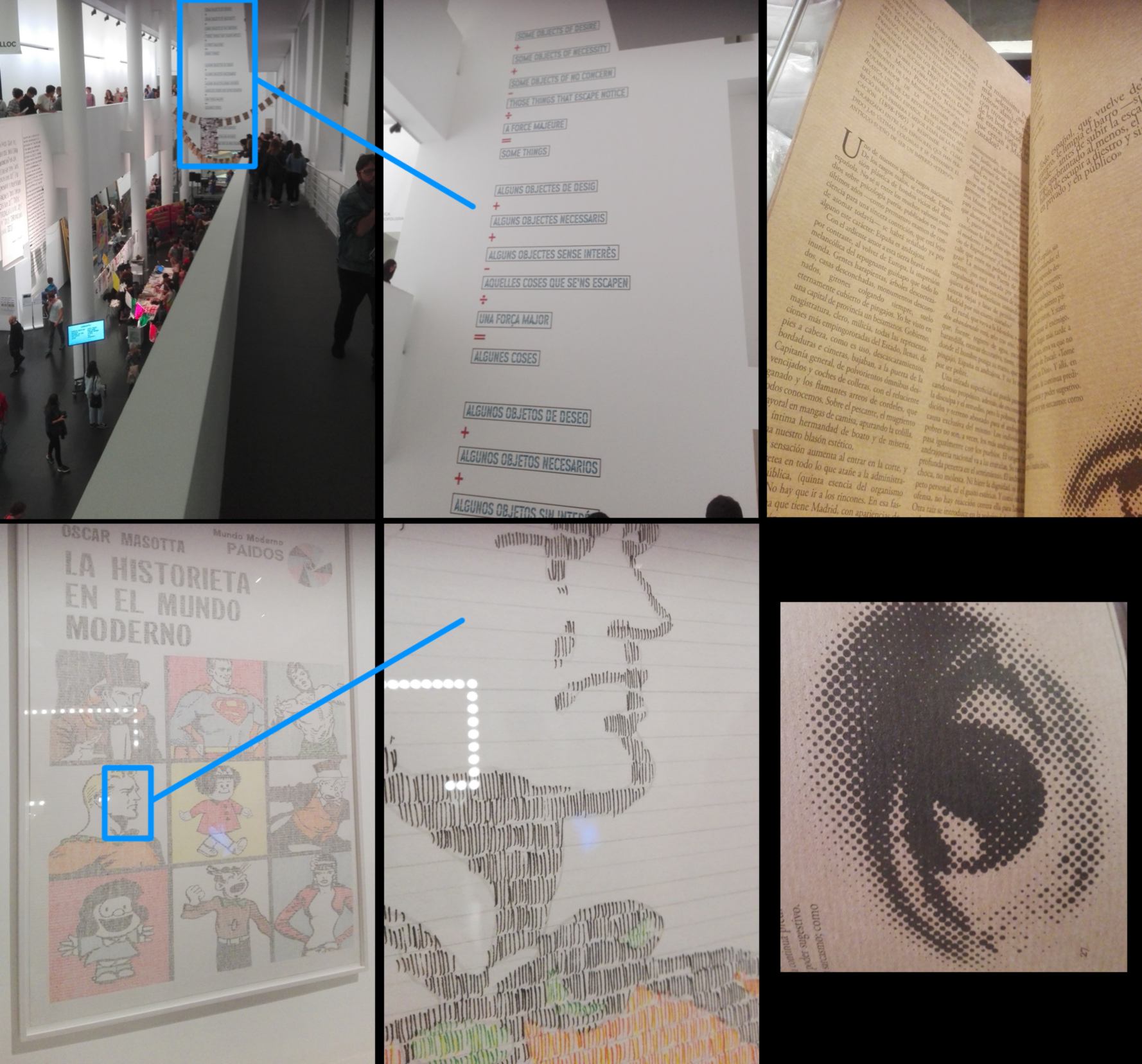
Tonight is a special evening where all museums in Barcelona are open and free, so I head to the Museum of Contemporary Art to see an ehxibition about comic books and printing. I find some design which would have greatly benefitted from the replicability and precision of a drawbot :
19.05.18 /I take a break to reflect on my work this week. I consider my design, and step back for an instant. This machine would solve an issue I have with the learning kit. I will develop on it for a sec :
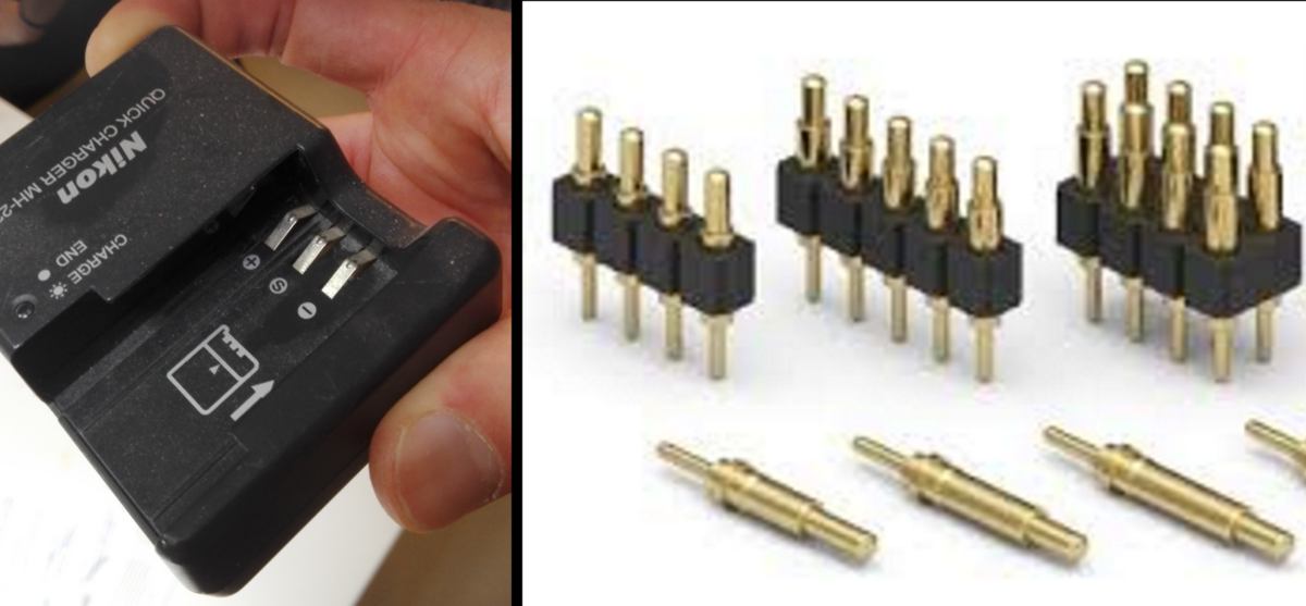
Since the learning kits are unlocked according to the level of the user, an identification system is required. Until this week, I had considered using RFID on each drawer to give or refuse access to each kit. This involved setting up an RFID reader and a processor for each learning kit as well as a locking system, all connected in a I2C network. Adding to the issue, each drawer could be put back in any available slots in the structure, so the RFID and electronics had to be located inside the drawer itself, which brought another problem to solve how to provide connexion and power to these pieces or electronics? Pogos connection? Something else?
Designing a pick-up machine with one single entry/exit point greatly simplifies the problem - the machine can classify the kit by itself, only one piece of electronics is required, no temporary connections for moving part is needed. But I doubt that my approach of adding an extra mechanism to my system of drawers will provide the most efficient solution. This doubt came to me while watching a video about a robot called Cozmo available on Amazon. This robot has been given some personality through beautifully animated motions, clearly insipred by the film Wall-E. And that reminded me of the storage system Wall-E uses in the film, similar to this one :
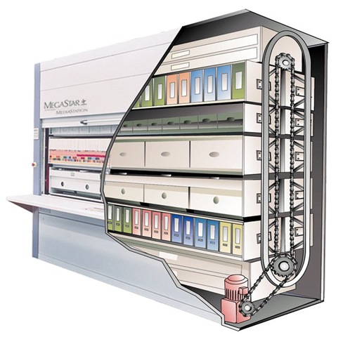
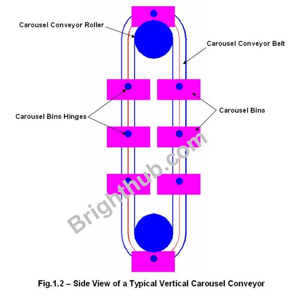
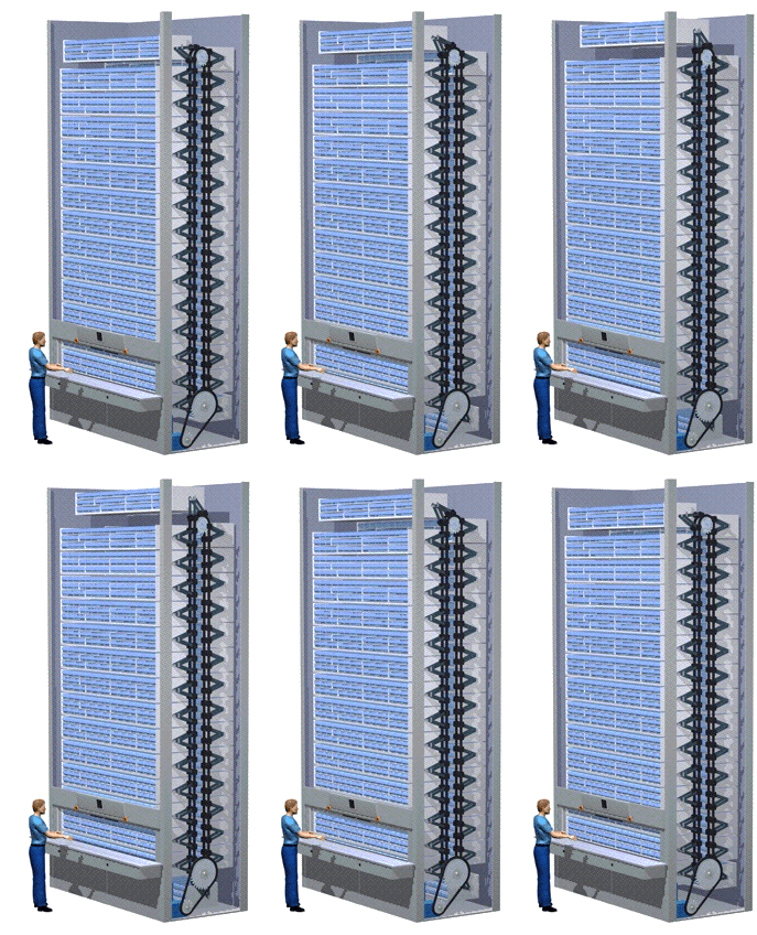
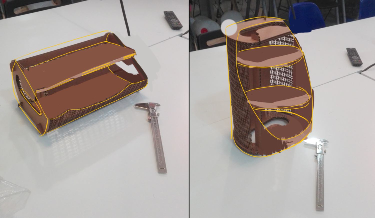
Using a single motor, this system makes better use of vertical space and provides access to several shelves. To perform the same operation, my current design would require two or three motors. I also notice that vertical carroussel are commonly used in several large-scale warehouse, which I take as a sign of reliability. I particularly like the following design, which is more straightforward :
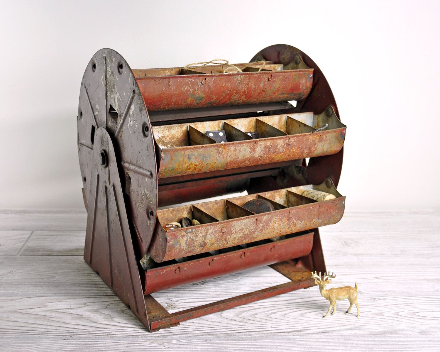
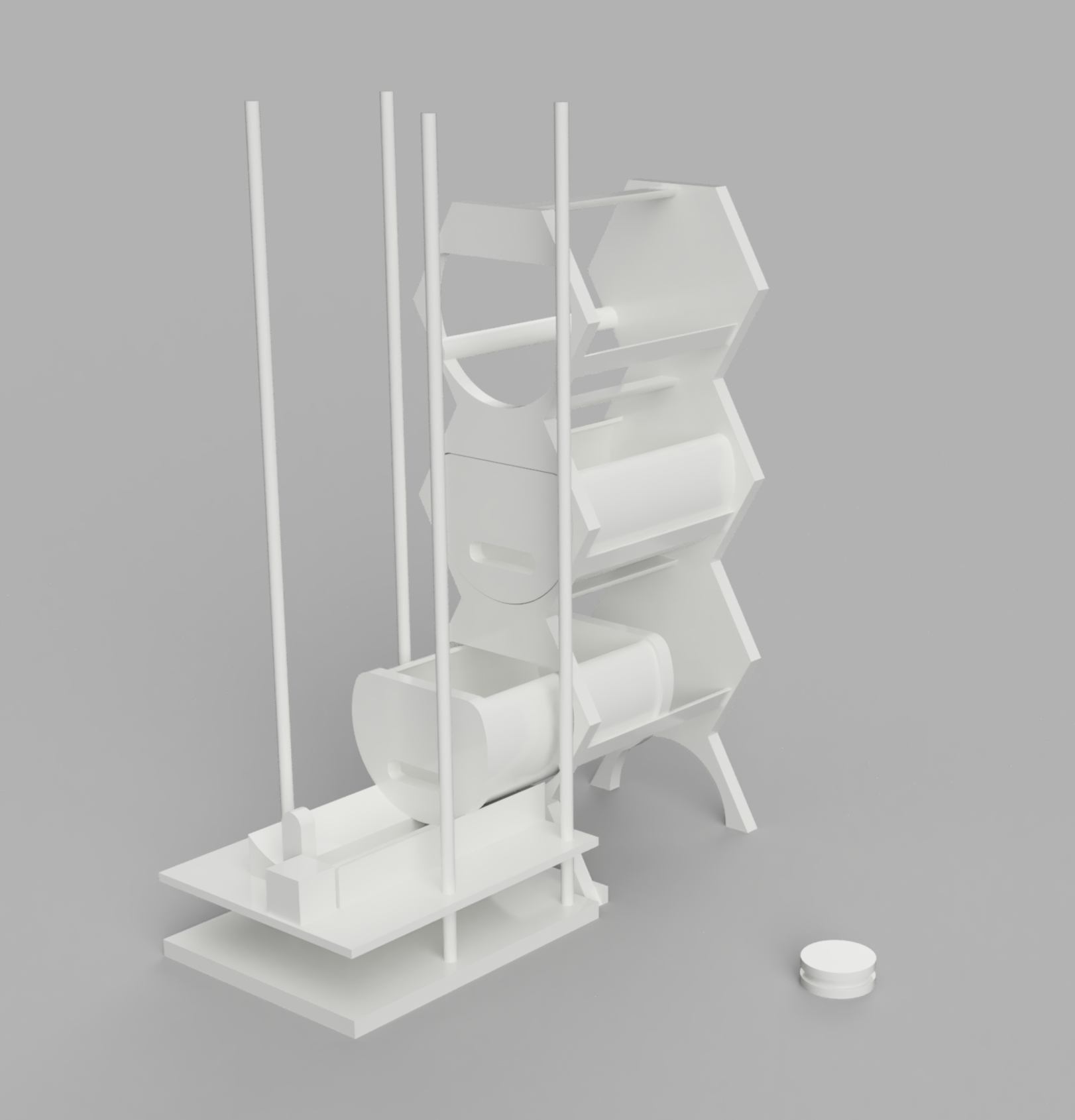
I sketch several versions, with different numbers of shelves. To make best use of the space and keeping in mind a potential vertical extension, the model with only three shelves is optimal.

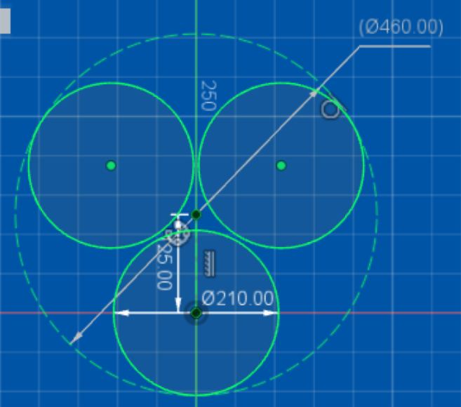
I re-design the drawer, and design the extra elements : shelves, rotating structures, stand, and connectives pins.
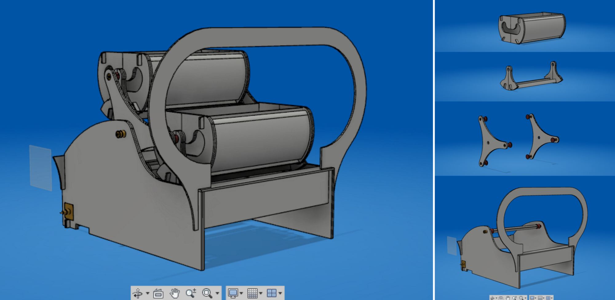
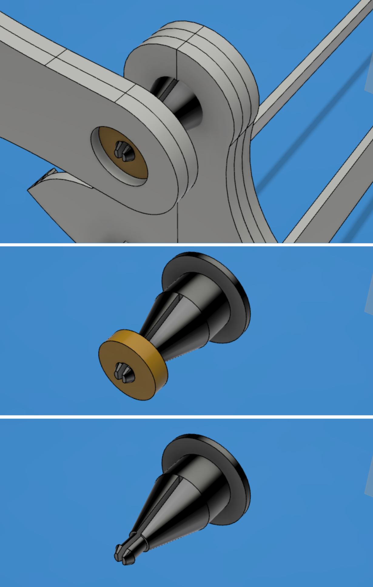
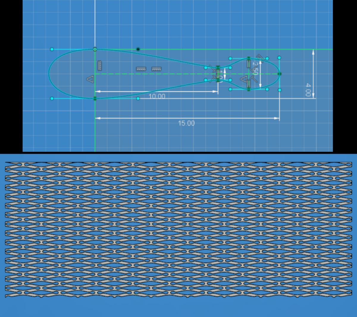
I then prepare the files for laser cutting / 3d printing. This include designing the round panel to the side of the learning kit. From the test cut I made a few months ago, I select the pattern which enables me to bend the material easily, and apply it to a rectangle the size of the panel lay out flat :
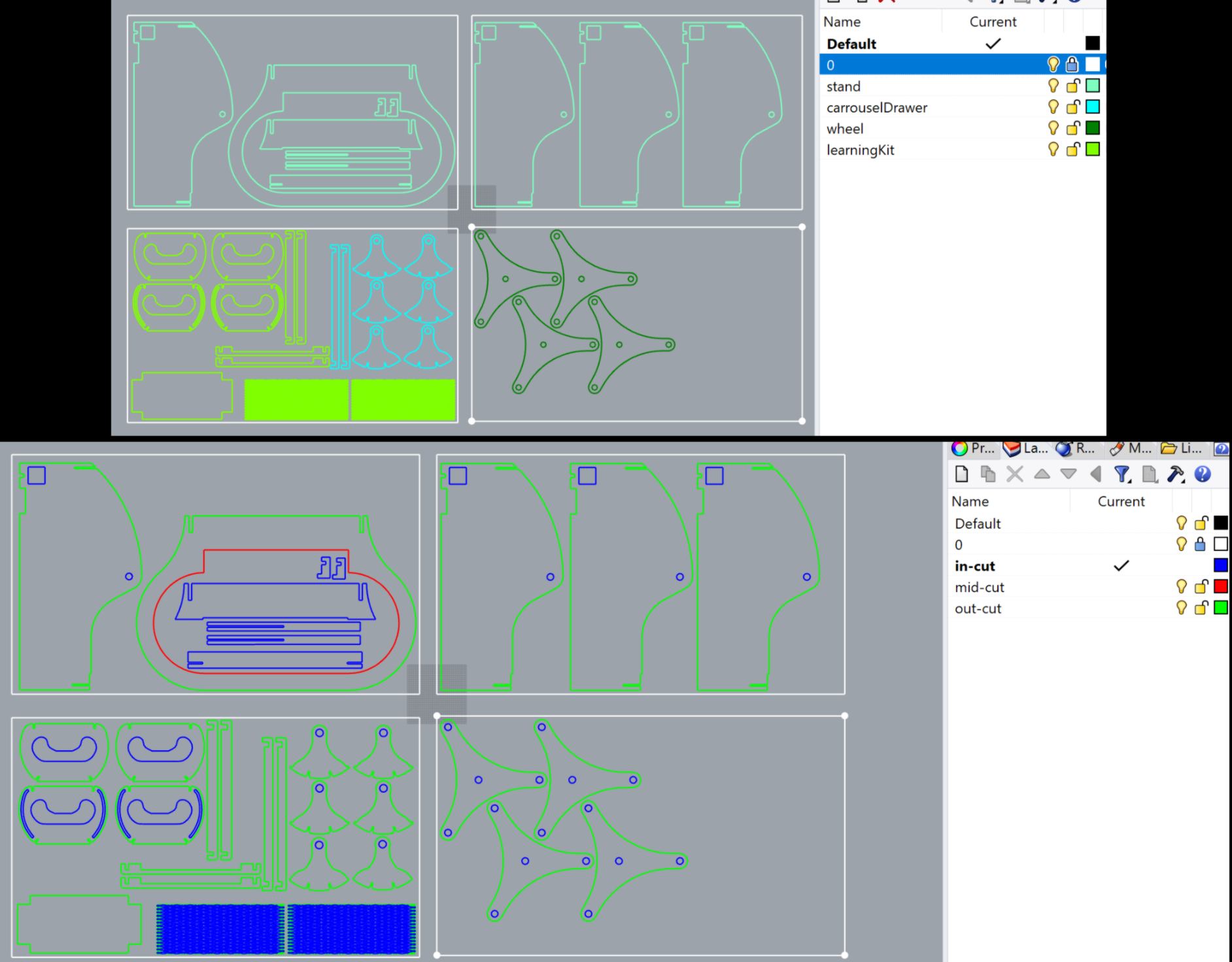
What is missing is the gears and belt system. I have exposed the moving part to the side so that I can add gears and a belt later on.
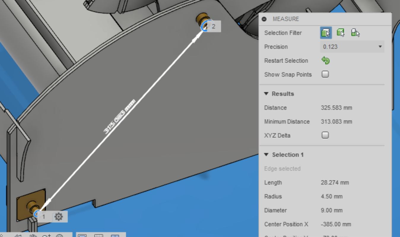
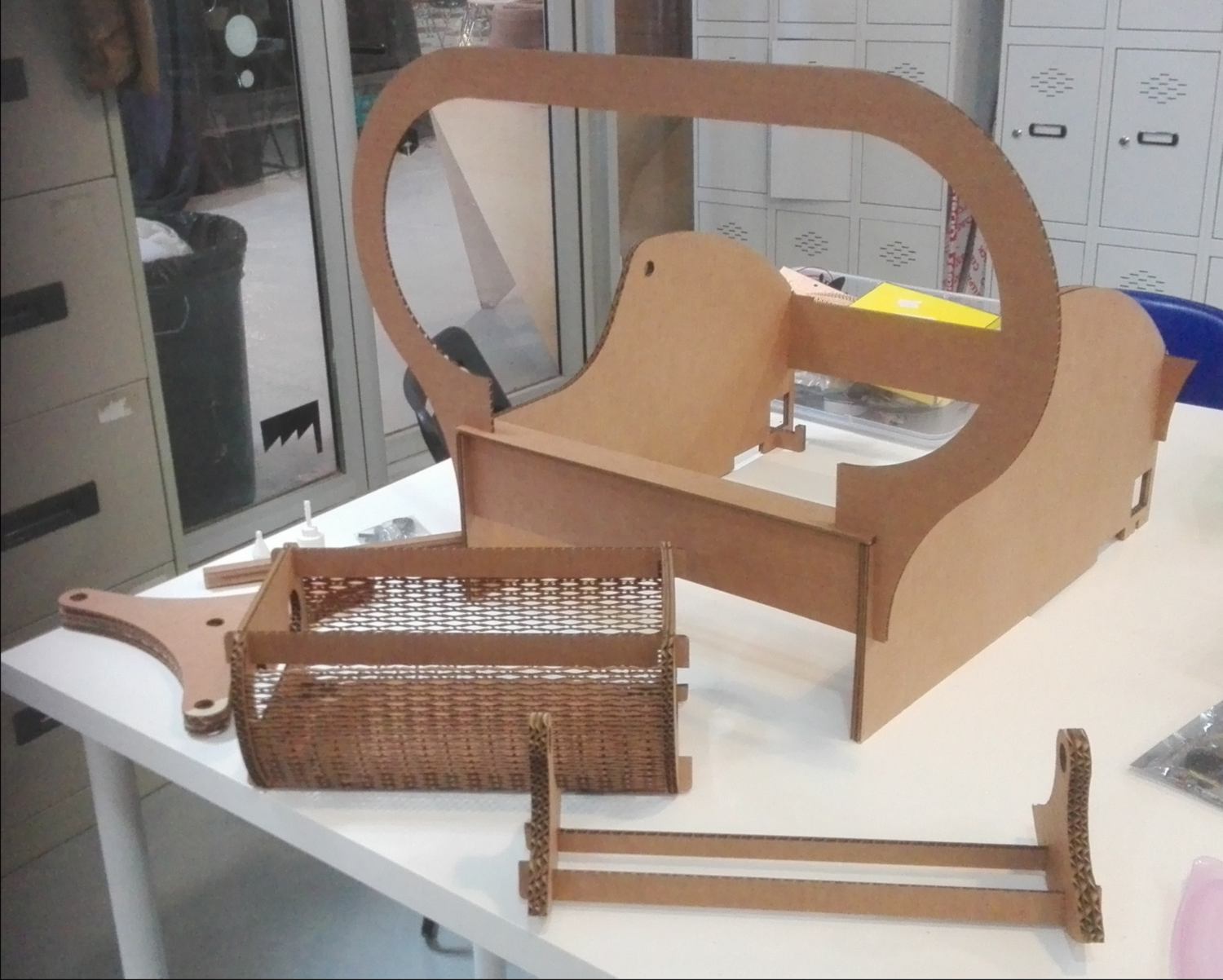
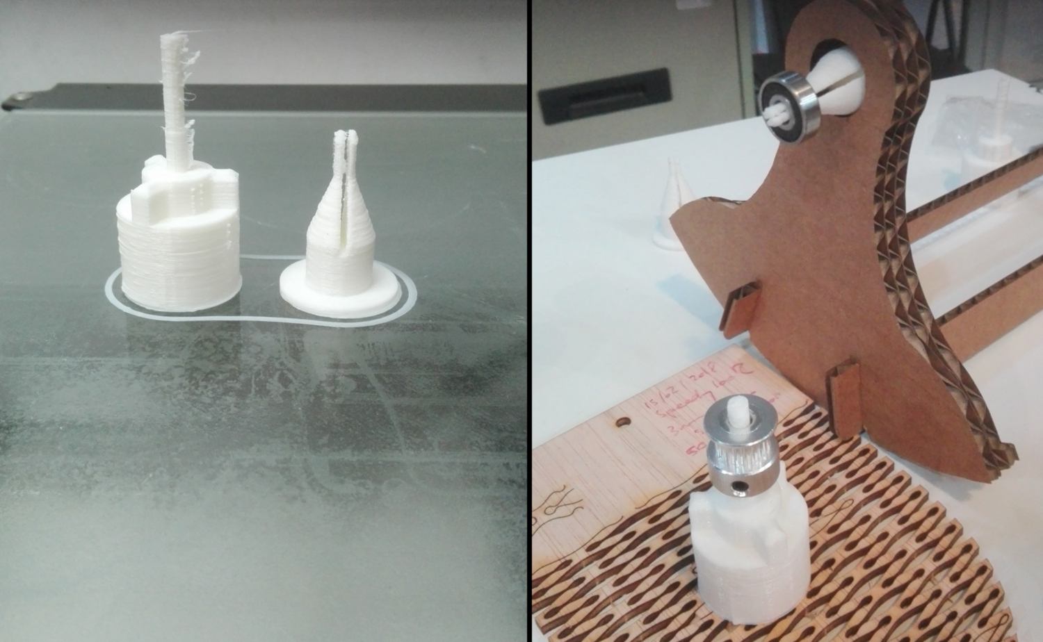
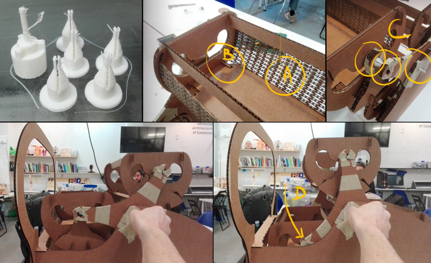
22.05.18 /I fabricate the machine using the laser cutter and the 3d printer. All cutted elements work fine. The 3d printed parts are troublesome. One is a design mistake on my behalf, which I correct (diameter issue). The other is badly printed.
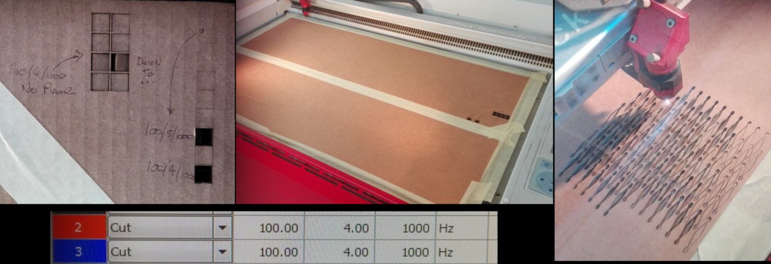
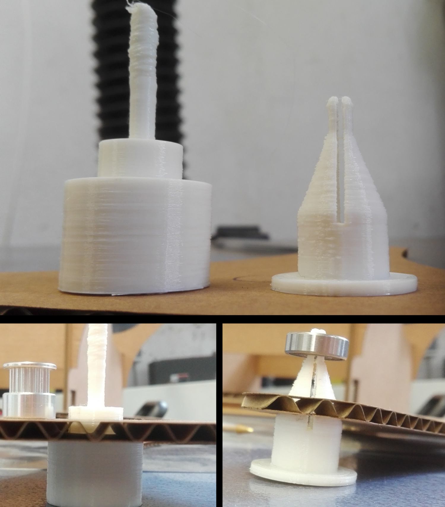
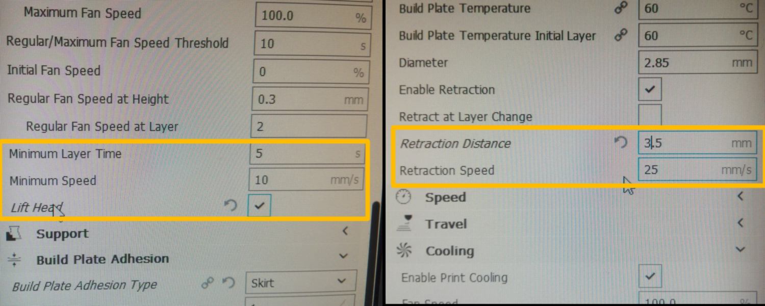
To remedy that, I modify a setting, forcing the printer to mark a few seconds pause between two layers, so that the former layer has time to dry. I also make minor changes so the wheel follows the rotation of the 3d printed shaft.
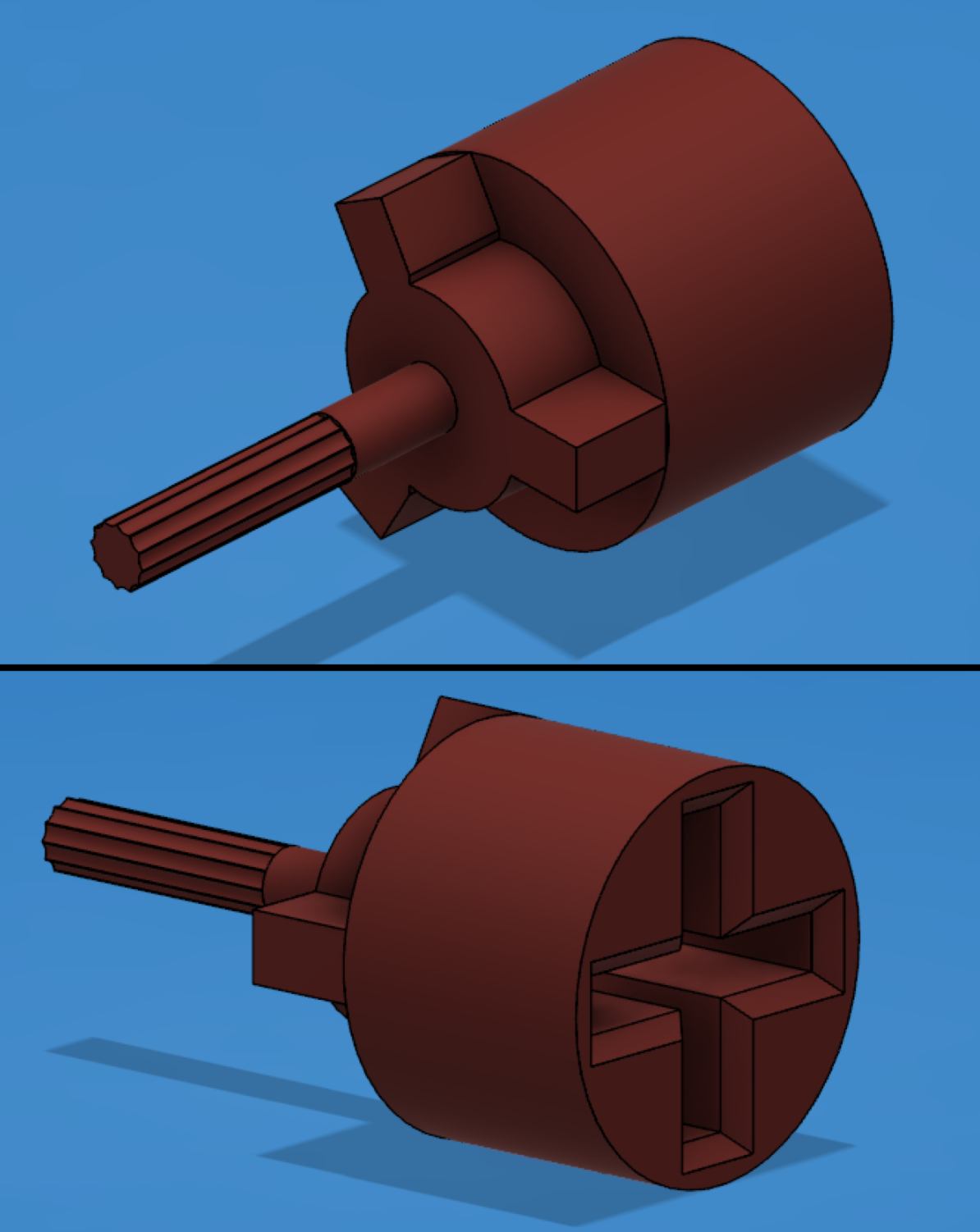
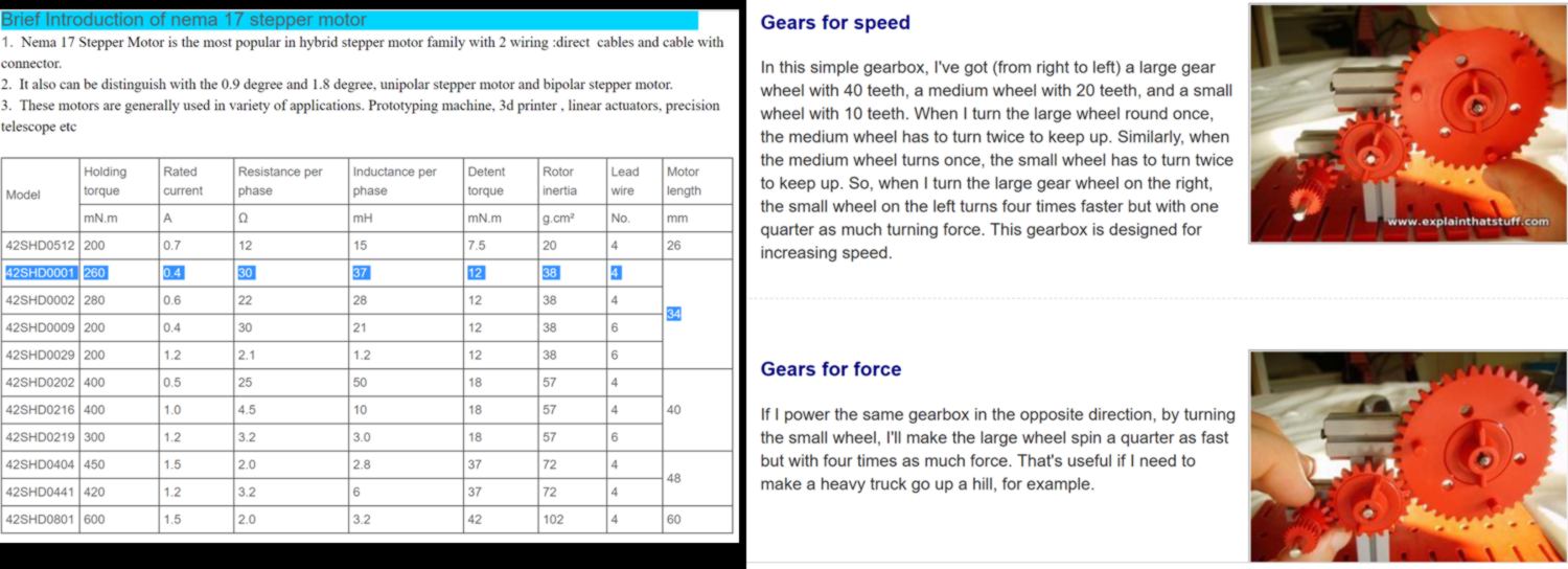
I begin to gather information about the actuation part of the design, stepper motors and gears :
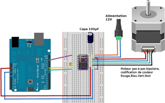
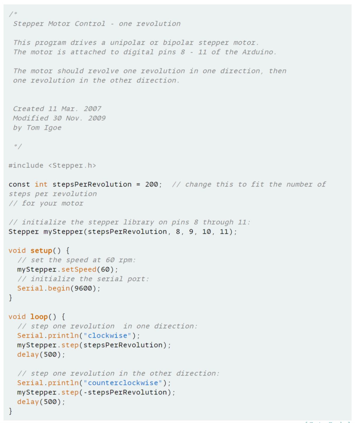
Using some documentation found on the arduino website, I set up some electronics and write some code to control my stepper motor :
23.05.18 /The 3d printed connections are ready for assembly :
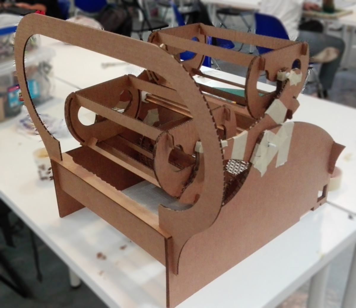
Overall the prototype is successful and functionnal. Many parts require improvements :
Back to the Iris pong : I receive the updates from other group members. So today I will wrap up the website, adding their input to the mix and writing a conclusion to the group assignment.
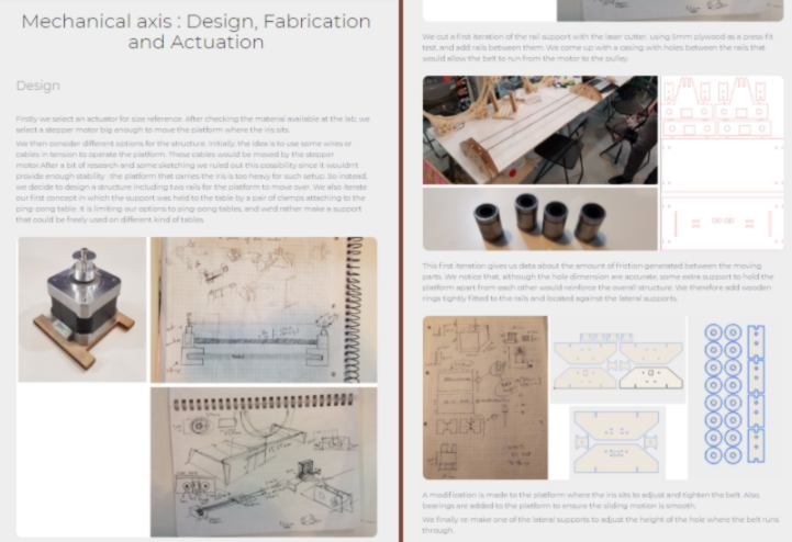
The website is available following this link .
24.05.18 / I plug the stepper motor in , connect the 12 V power supply and load the following code, initially by Tom Igoe and re-edited to fit its purpose here :
#include < Stepper.h >
const int stepsPerRevolution = 800; // change this to fit the number of steps per revolution for your motor
// initialize the stepper library on pins 8 through 9 (two pins only!):
Stepper myStepper(stepsPerRevolution, 8, 9);
void setup() {
// set the speed at 15 rpm - slow for testing purpose
myStepper.setSpeed(15);
// initialize the serial port:
Serial.begin(9600);
}
void loop() {
// step three revolutions in one direction:
Serial.println("clockwise");
myStepper.step(stepsPerRevolution*3);
delay(2000);
// step three revolutions in the other direction:
Serial.println("counterclockwise");
myStepper.step(-stepsPerRevolution*3);
delay(2000);
}
Side-note : You will see below why I have specificed three revolutions.
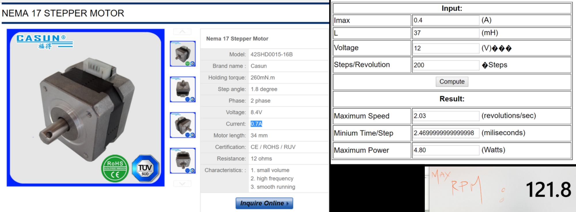
The overall amount of weight the motor will move might become important in the future, so I would rather use a gear train and let the motor spin fast to move the overall wheel slowly. I then look at its maximum velocity. To do so I use an online stepper motor calculator and a description of the stepper motor . It turns out to have a max rpm of 121.8.
I encounter an issue : the stepper motor only turns in one single direction. The issue might come from the driver, the code or the wiring. I replace the driver with another one but the issue persists. I then check the wiring and adjust it according to the datasheet of the stepper motor (the order of the wirings and pins are different and requires modification :
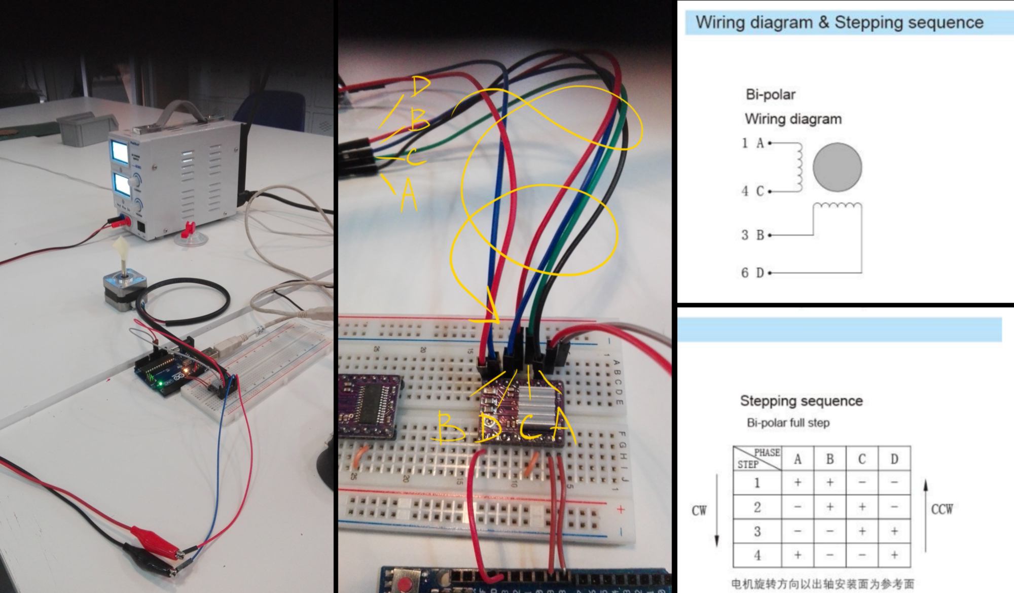
The stepper motor makes less of a ruckus, but the issue remains. I go through the code and modify the definition of the stepper function, getting rid of the two last pin defined (since I do not have them). It does the trick.
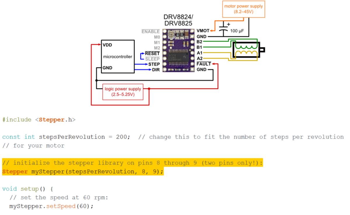
For this machine to present one kit, then another one to the user, the mechanism has to turn precisely 120 degrees. However the stepper motor turns by increment of 1.8 degrees, therefore, even using half stepping, the stepper motor cannot precisely stop at an angle of 120 degrees, and overtime it will become fully misaligned :
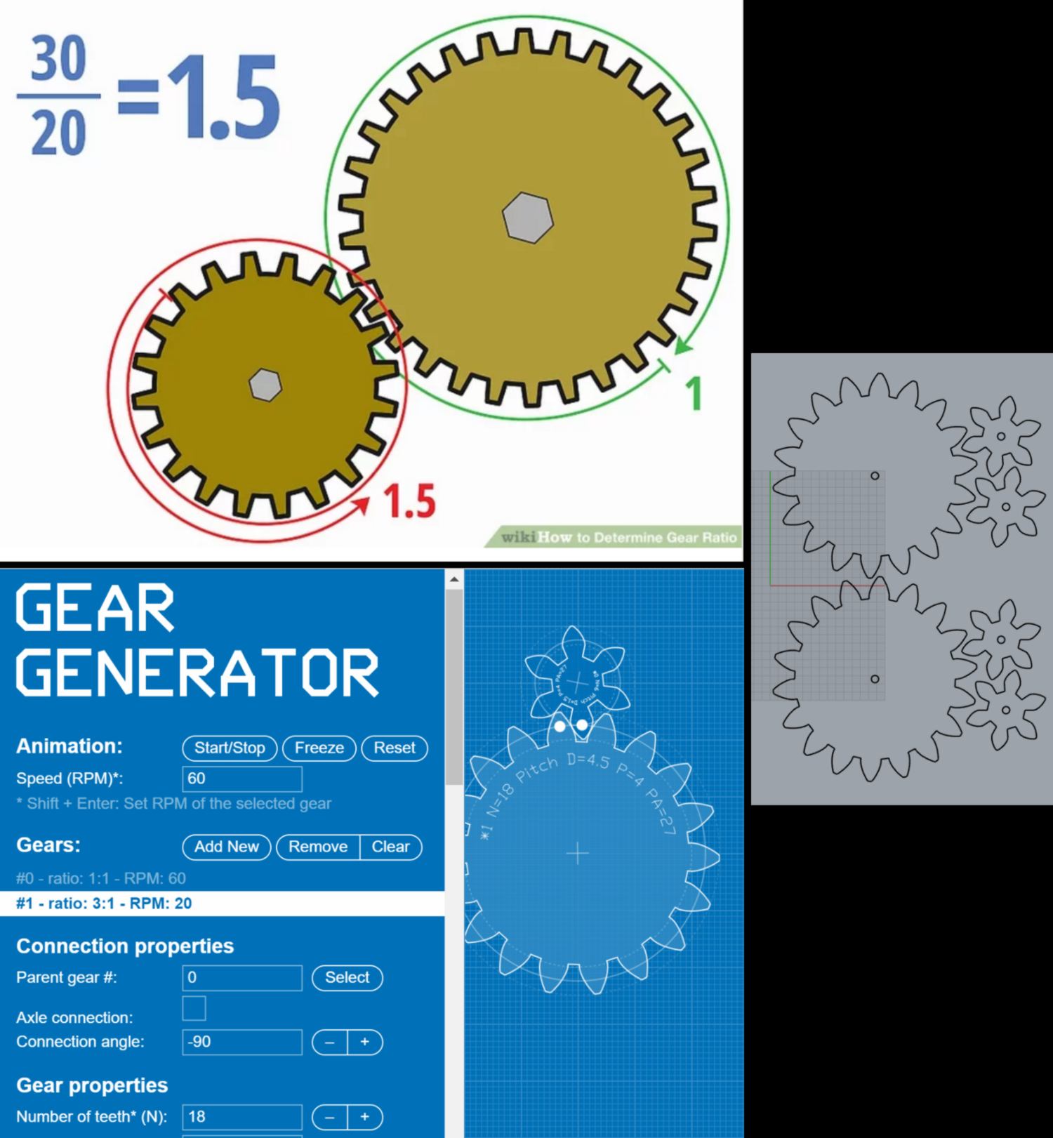
to solve that problem I look into using a gear train and calculate the accurate gear ratio. I find an online gear generator, and design a small gear with 6 teeth and a larger one with 18 teeth. When the small gear (driven by the stepper motor) will perform a complete rotation, the large gear (the mechanism) will turn by precisely 120 degrees. I go laser cut these pieces and fit them to the side of the machine. I will have to design an extra 3d printed pin to hold the gear, also fitting in a bearing lodged in the cardboard, in a very similar way as the ones previously used for the moving structure.
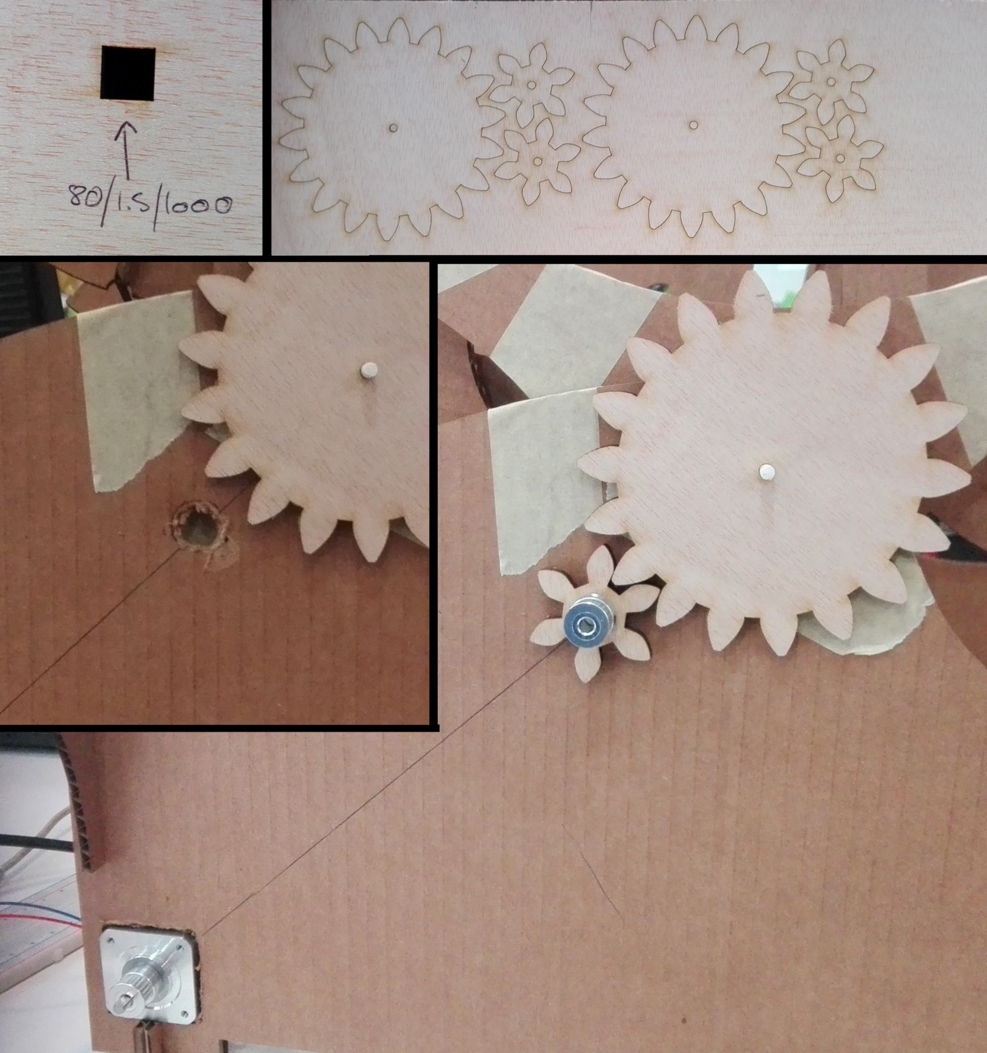
I then 3d print a belt tensionner found on thingiverse and add it to the mechanism, then launch the code. The stepper motor spins correctly, the tensioner moves from on point to another without hitting the gear, and the rest of the wheel spins slowly, performing a full rotation.
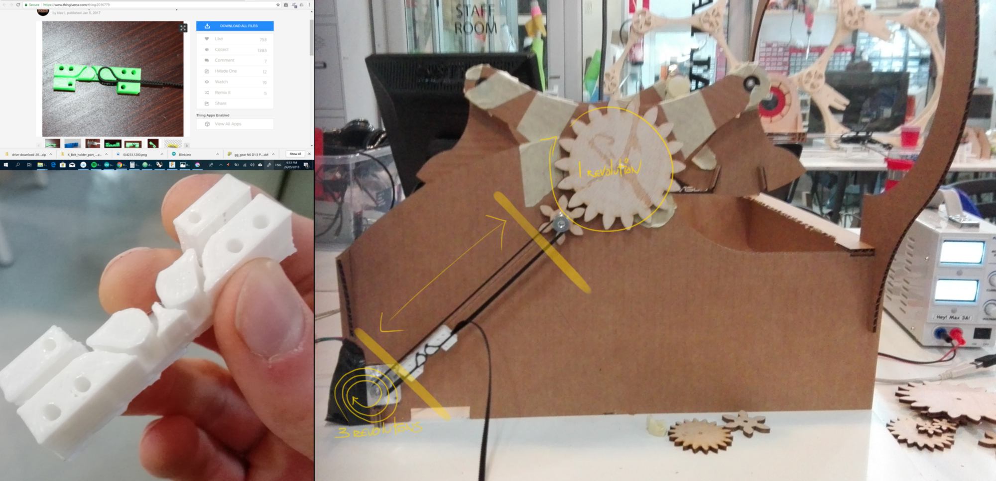
It is successful. In a future iteration I would modify a few things :
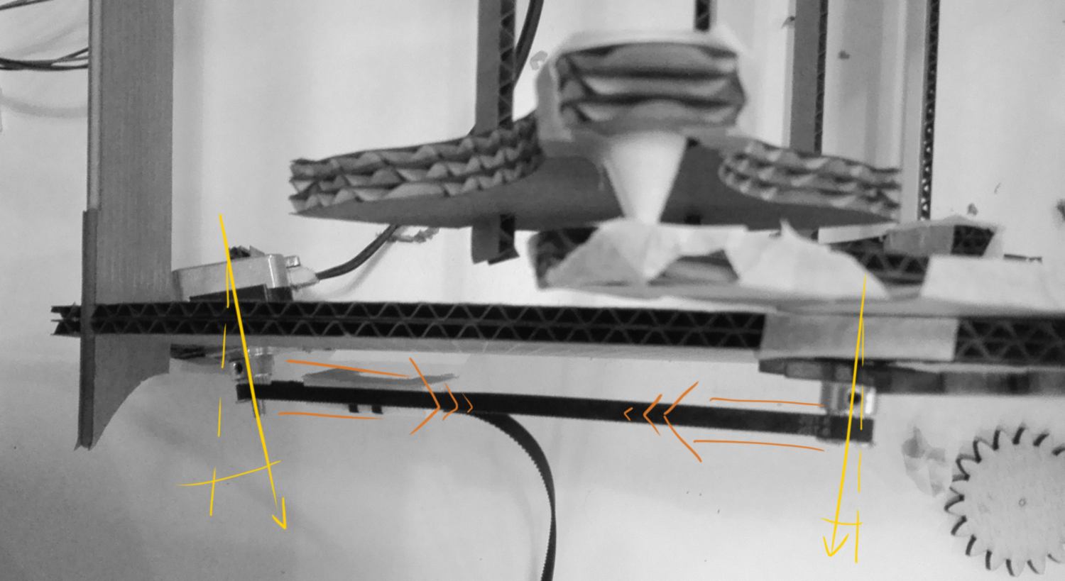
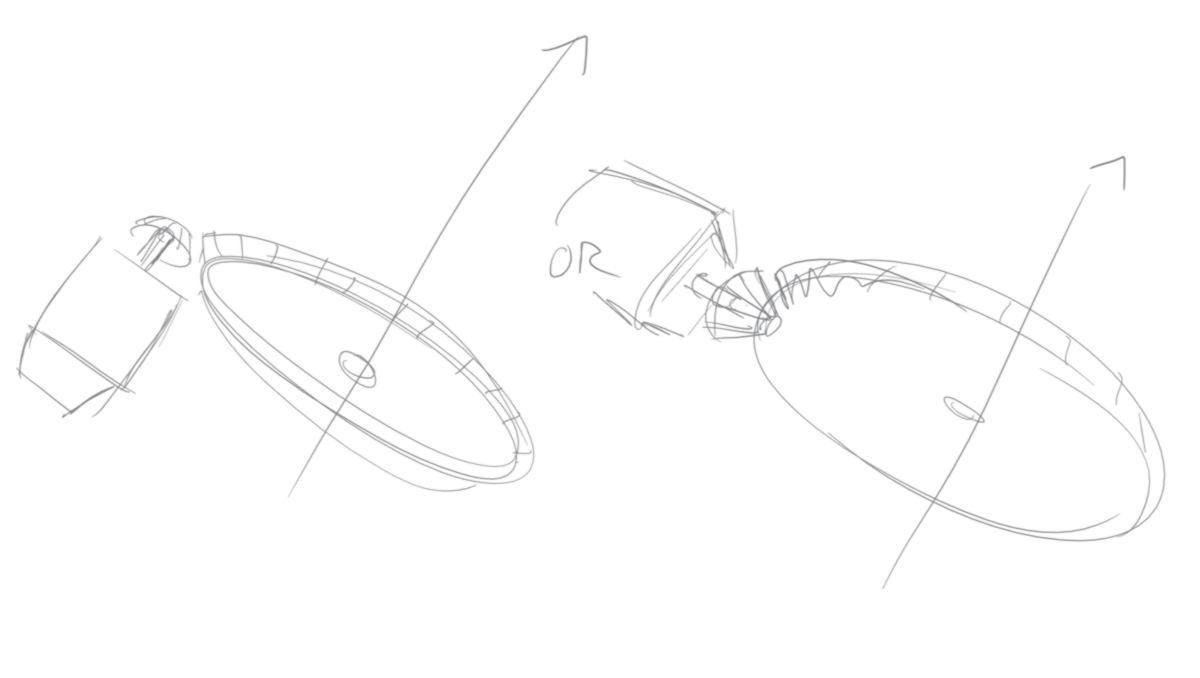
I will leave it there for now. This assignment was by far the most exciting. The technicality behind actuating correctly different moving parts is challenging and rewarding. It takes a increasing amount of precision as the size and weight of the objects become larger, Not to mention the fact that friction is an irritating reality at time.
Finally, and I wish I will have time to explore that in a near future, the inertia of a body must be taken into account to generate smooth acceleration and deceleration. I guess my former trade as an animator is still very much alive deep inside.