Milling, and Soldering
First of all i downloaded the images of the board, and i milled and then i soldered.
Download: Board

This week I made a mutitouch pad based in Matthew Keers work. The intention is make it, and then modify the processing code to change the visualitzation.

Download: Board
My first thought to have the board soldered was, and now how can I program the microchip!
The board design has no ISP connector, so I had to improvise a solution.
Noticing the scheme of attyni 44, I looked where they were the VCC, GND, RESET, MISO (pin 6), MOSI (pin 5) and pin 4. I soldered a connector for these pins. Then I plugged it into a 6-pin connector to program with FabISP.


- First of all i downloaded the Code.
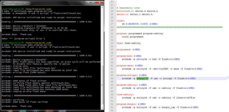
- Open the terminal go to the specific folder and do the Hex file // make -f multitouch.make

Here I had to open the file "makefile" and change the line "ATmega168" with "attiny44".
- Program the tiny 44 // make -f multitouch.make program-avrisp2
I download the Matthew Keeter's code, and i tested it.
After testing the code. The problem I had is that the device had not react very well for some pads. And there was no way of knowing which failed because the initial size of the cubes was not linked to the sensor signal.
So I decided to modify the code a bit to better visualize the intensity of which was read the sensor signal.
What I did was change the display by circles and assigned the initial radius of the circle to the initial signal of the sensors.
After all I did was to link the growth of the circles with the signal from each pad when touched with finger.
After I changed the view display. From a perspective view switched to a plan view. I think it looks a little better.
I can see and download the program code.

As you can see there are some problems with the sensors. There seems to be connected with each other and others who just do not react very well. Would have to check again the welds of the board and see what is going wrong.