|
Week10: Input devices
Another electronic week. This time lets try to see what can we do to collect data from a electronic board with an ATTiny45 chip.
Reading the Datasheet
This week we are going to work with a new ATmel microcontroller, the
ATTiny45. First of all we need to read the datasheet of the
microcontroller:
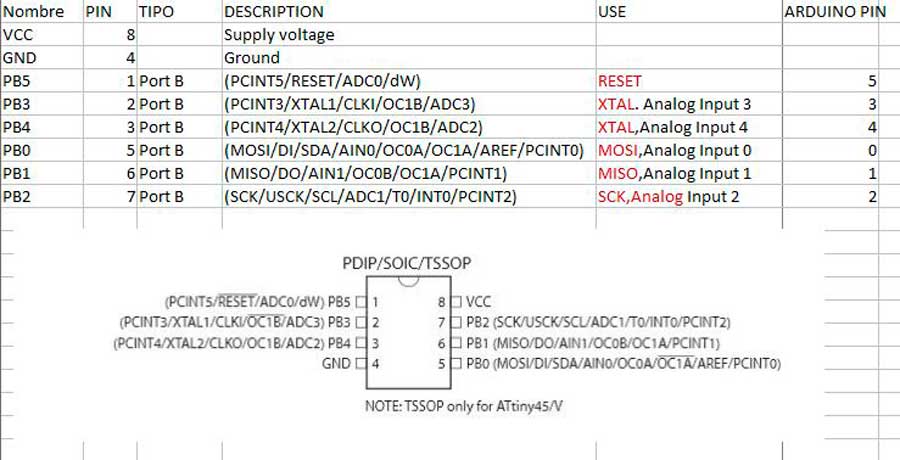
After read ir we realize that this microcontroller has only 8 pins,
where pin 8 is VCC, pin 4 is GND and the rest can be configured as
Input devices. In datasheet the pin number 1 is RESET, the number 6 is
MISO and number 5 is MOSI. The programable I/O pins are 2 and 3 pins,
named PB3 and PB4.
Here is the resume:
Building the Hello Light board
I
choose the Hello light board, where we can collect the amount of
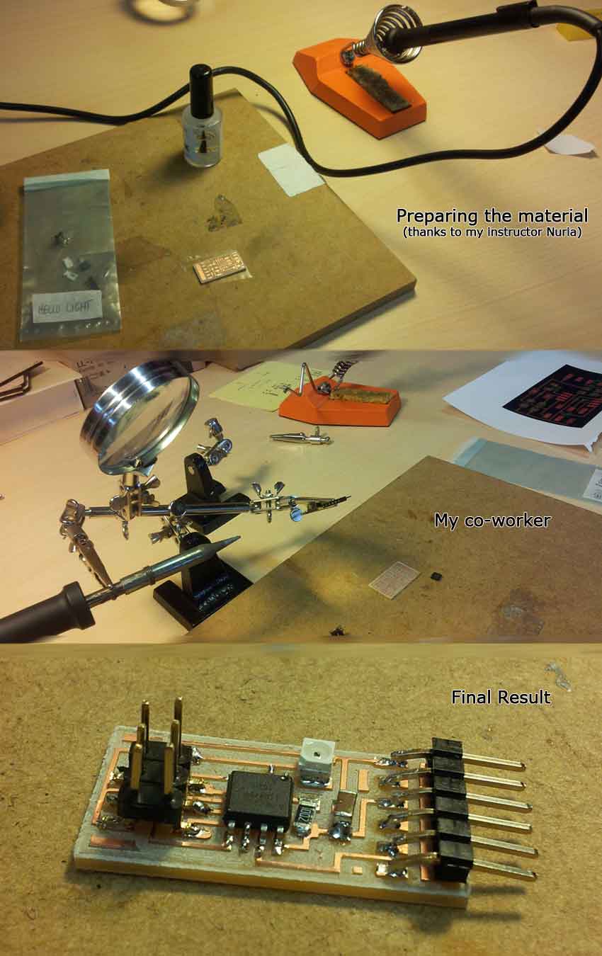
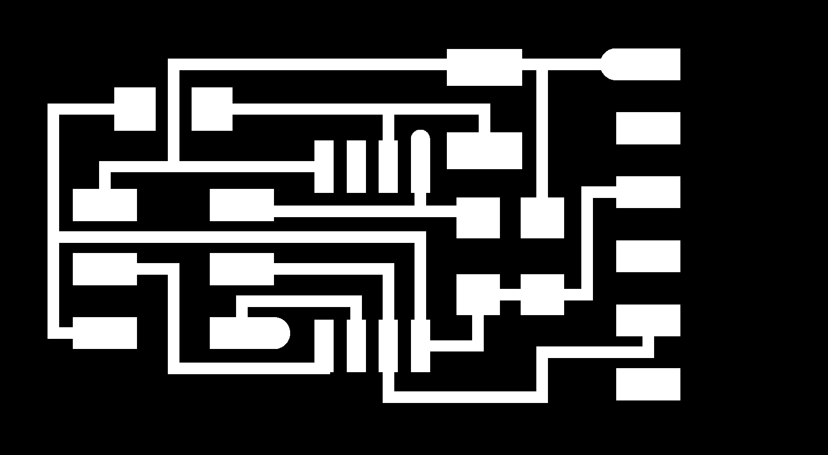
enviroment light. Now first lets build the board. First we need the
layouts of the board, interior and traces.
After this we need the Roland Modela to do the board. Put the copper board at the Modela, and open the fab modules.
Select the image (png) option, and put the Rolan Modela as output. Load
the png file and establish the parameters to cut the board.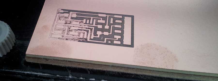
Again
we had some problems with the base of the Modela. It seems that
something curved the copper board, so i had to make a second pass
adding a 0.05mm to the 2DZ parameter. Finally tha pcb gets cut: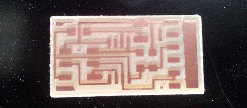
The components needed to build the Hello Light board are:
- 2 Resistences: 10k and 49.9k (named 4992)
- 1 Capacitor 1uF
- 1 ISP connector
- 1 Attiny45
- 1 FTDI connector
- 1 Phototransistor
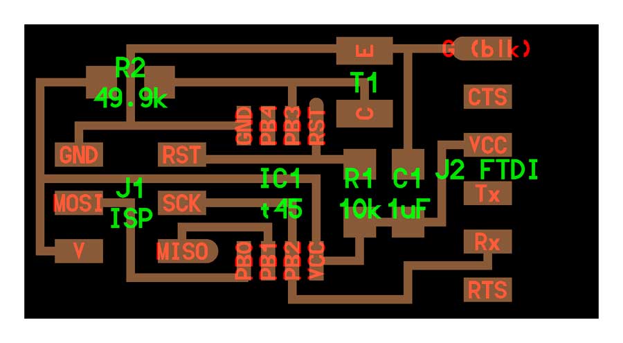
Lets solder the components in the board as the squematics shown:
And here is the final result (every day my skills in soldering are going up ^^):
Programming the board
This
boards are input boards, so we need to see what data collect the
microcontroller and see the variation. For that lets use the python
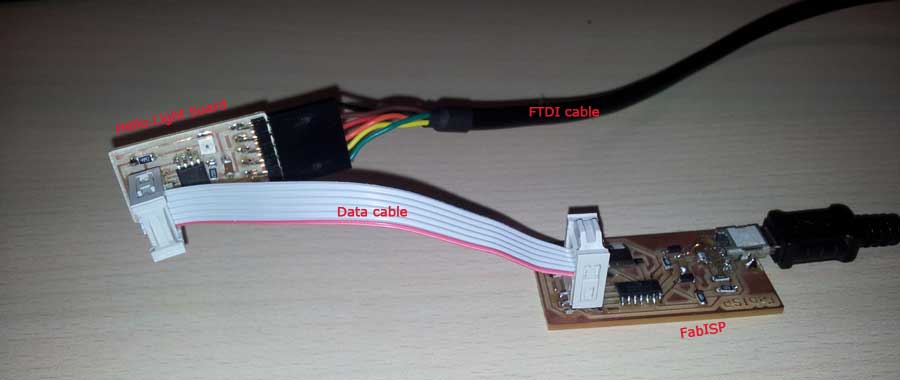
code disponible in the fab academy page.If we take a look at the PCB COMPONENTS, we can see that the phototransistor is connected to the PB3 pin.Now, lets program the pcb Hello.Light. We need a FabISP, a data cable, miniUSB cable and FTDI cable. Lets connect all:
Now we need to flash the program. Download the files needed from Fab Academy:
Once we have all files, in Ubuntu,open a terminal and go to the folder where you stored the files.Lets flash the board:sudo make -f hello.light.45.make program-usbtiny
Now we have the board flashed, lets try to see the data on the screen. For this, in Ubuntu, we need to install a library:
sudo apt-get install python-tk
Now lets open the windows to see the light variations that the phototransistor colect:python hello.light.45.py /dev/ttyUSB0
With
this command a windows must be opened in the desktop, with a valor
depending of the light received. Here are a photo with camera flash and
another without flash, where I can see the variation of the bar: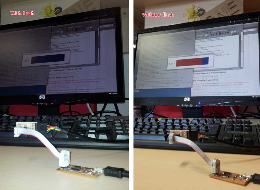 As
we could see, the phototransistor gives high valors for the dark and
low values for the light. So the phototransistor gives the amount of
dark , not the amount of light.
|