My name is Pablo Nuñez, im from Leon and a
student of the Fab
Academy 2013 here, in Fab Lab Leon.
Objective:
Try to build a R2D2 figure with a remote controller.
Accomplished:
-Main structure completed. All made in foam 3mm
thickness sliced and joined toghether. One main cilinder for the body,
a semispheric head and three legs, two of them equal.
-Scale and final measurement. I wanted a small R2D2,
finally about 30mm tall.
-Middle leg made completely in 3D Printer. This leg
doesnt have motor, so no need to introduce electronics on it.
-Integrated DC motors into the side legs. Two small DC
motors embeded in the foam.
- Programming the movements in Arduino. This program
will move the robot forward/backward/sides.
-Remote control made through an IR sensor and a remote
from an old Digital TV reciever.
-Electronic fabricated. After several efforts in some
pcb, finally a fabduino will drive the motors.
-Composites covering the main body. Finally a white
linen covering all
the body, giving the final aspect and keeping all pieces toghether.
To Do in the future:
-Add some leds and a speaker, to make R2D2 noise.
Building the main body
The first of all i want to do is
the body of an R2D2. I wanted a light material and easy to work with
it, so i decided to do in foam . To make a 30cm tall R2D2 i had a 3cm
width foam, so i must design the main body with this size.
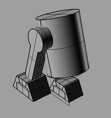
So first i design a schematic R2D2 with Rhinoceros 3D,
some cilinders and other pieces.
After this i extract the profiles of the pieces in 2D
and export it in dxf, file format needed to CNC milling in our fab lab.
After exporting, with the Aspire software, i define some depth milling
the foam, to make the foot. The foot will have the motor inside and the
wheel.
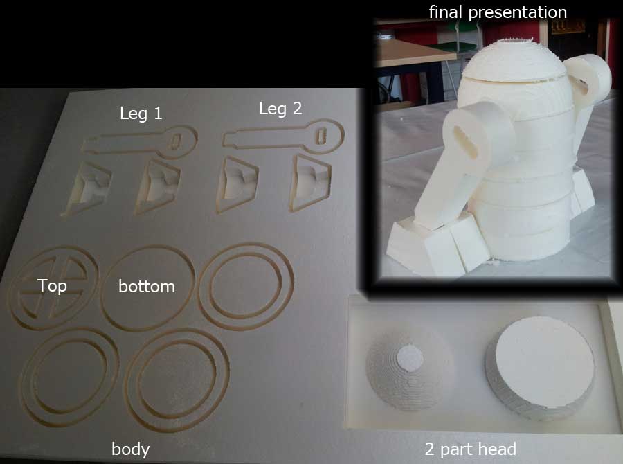
Here are the
pictures to build the parts of the R2D2:
All pieces were sliced and taking to a CNC machine, to
cut all the
traces. There was two diferent type of sns milling, a 2D milling for
the legs and body, and a 3D milling for the head. All were made with a
6mm planar drill. Thats why the head has a very bad finish,
with stepwise. So after milling i need to sand the surfaces to have a
smooth finish.
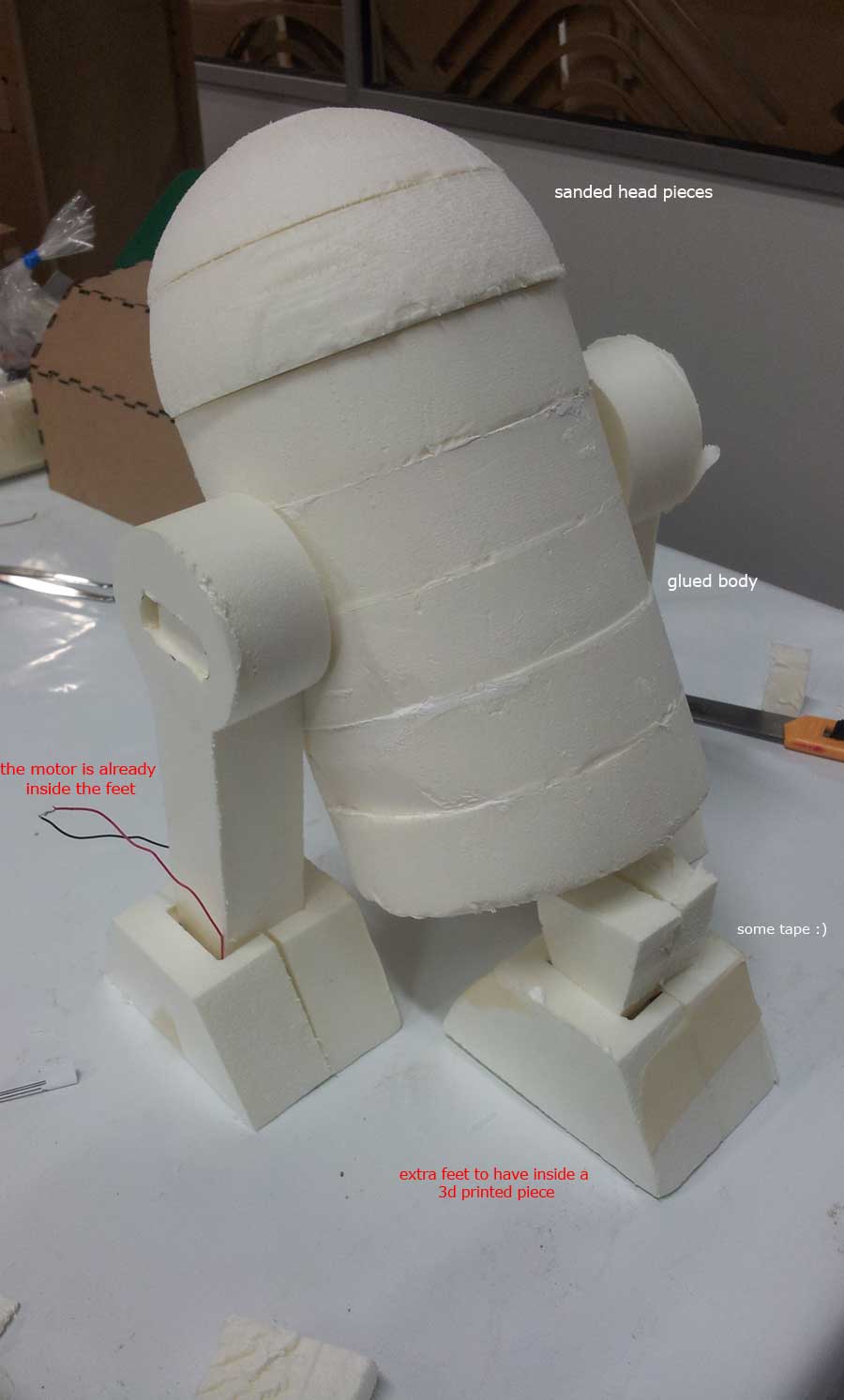
After that i use some foam glue to join the parts and
make them solid. This wont be the finish, because all the robot will be
covered with composite, but i need a clear idea of the final, to build
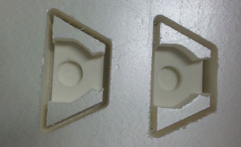
the legs and the introduce the electronics. I also mill another feet ,
because the front leg will have a 3d printed component, and i need to
adjust it to the height of the robot. So here is the final assembly:
The interior of the main body is empty, to housing the
electronic
components.
MIDDLE
LEG 3D PRINTING
The middle leg of the R2D2 wont have a motor, and i
need that this leg help robot to turn correctly. So i realize that i
need some kind of ball, to turn around and follow the robot movement.
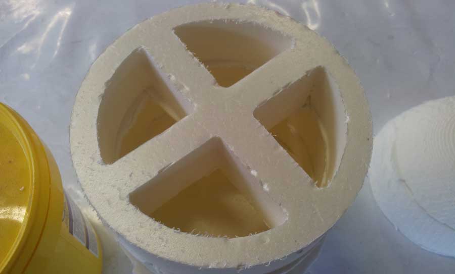
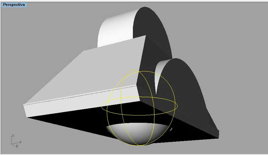
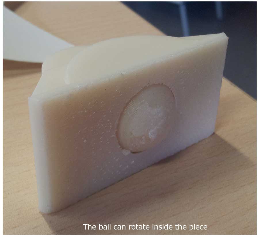
So i decide to make a 3D model that have a main structure, with a hole
inside on it, and a ball inside , a little more small than the hole. So
finally the ball will turn inside the strcture, and it wont go out,
because the hole keeps it inside.
I did this design in Rhino 3D, where you can see the structure and the
ball as mesh:
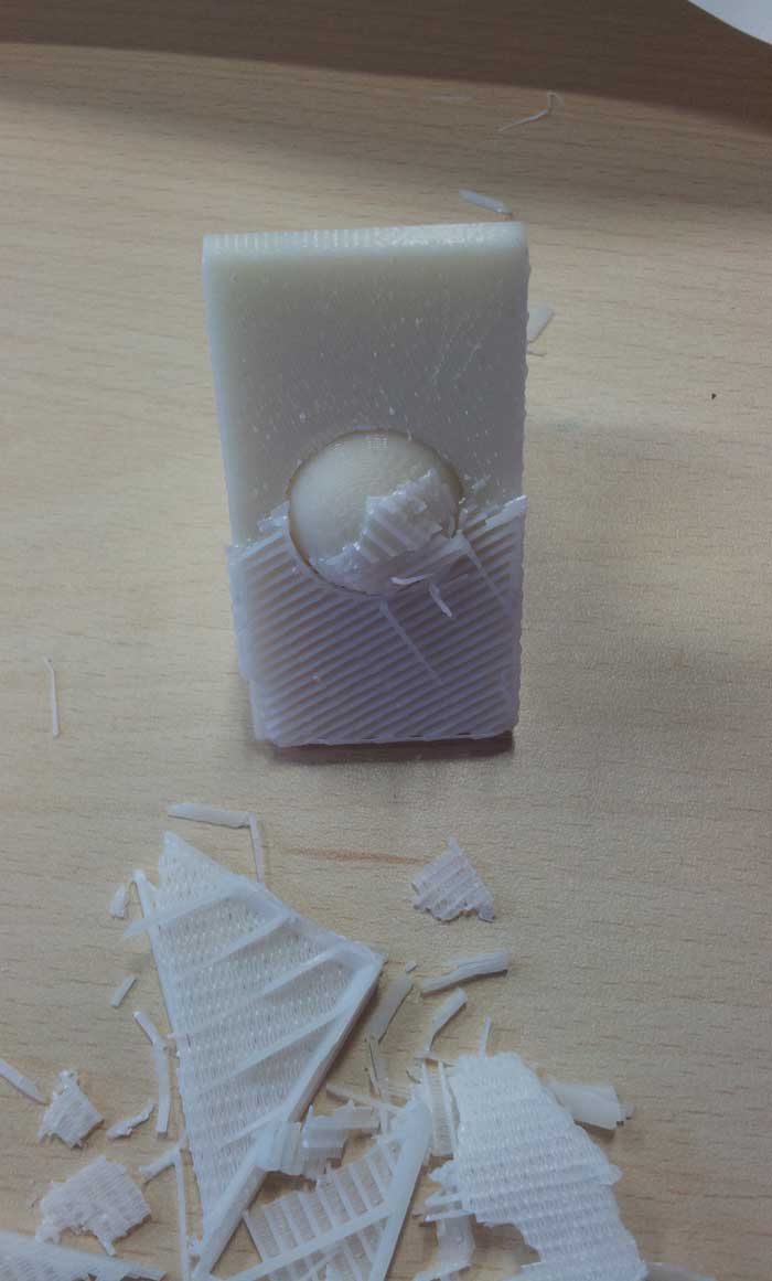
Then i print it in Fab Lab Leon, with our HP 3D
printer, that gives a smooth finish (with some support material that
needs to be removed).
Starting
with the electronics
The first thing i need was a way to control the DC
motors i had recicled from a RC toy. In the Hello boards of the Fab
Academy i had an example of a HBridge pcb to control a DC motor, so i
start at this point.
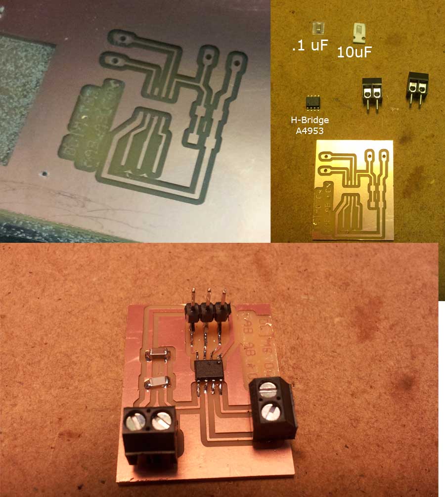
The H-Bridge A4953
used in the Hello Bridge only let me control one motor, so i
realize i must make two pcb, one for each motor. I did a first try with
a pcb that contains a A4953, a conector for a 6v battery, a connector
to attach the motor and 3 pin connector to comunicate with the fabduino
or other controler pcb:
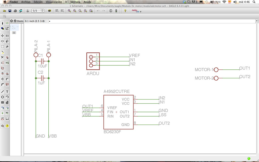
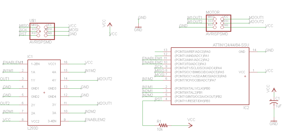
Here is the schematic:
milling the pcb and soldering components:
Finally
this design didnt worked, because has some problems of
design. Under the A4953 there is a GND pad that i dodn see, or maybe
other questions i cant even understand.
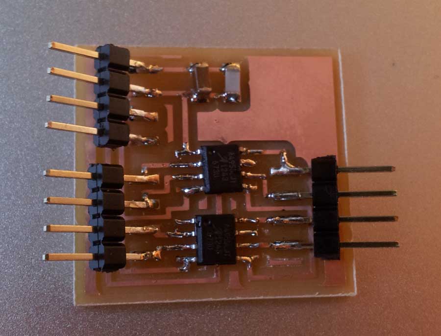
After that i make some search on the internet, and find
the proyect of Dan
Sawada in the How to make almost anything course of
the MIT. Dan make a pcb that contains two A4953 to control two
motors...exactly what i wanted! so i give a try and download
the files needed to build the board. The result was great...
but it didnt
worked at all. In the Spreadsheet of the A4953 says that
under the chip there is a Pad that must be connected to GND, and i dont
put solder under it....maybe this was a mistake. I really dont know why
this board didnt worked, later i will give it another look and find the
fail.
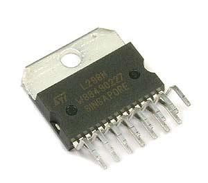
...another chip maybe the solution...
This chip only controls one motor, so thanks to may
mates in Fab Lab Leon i make another try with other chip, another
H-Bridge called L298n,
to get a total control over the both DC Motors. This time a make a try
with an Arduino breadboard before milling, to know if i can control the
motor with this chip.
Another deception,
i cant even move one motor with this chip. So i search for another
chip. Lately i realize i was working with a broken chip :S
After my instructor Nuria show me a video configuring an Arduino with
other chip, i give a try to the L293D chip. This chip can control two
Dc motors, has enable pin for each motor and, the most important thing,
I COULD PROGRAM IT! :)
Trying the chipset in arduino, i realize i can move the both motors
easily. To control the motors for this test i use an arcade stick that
i used in the arcade machine i build in Computer
controlled machine:
Now i design a pcb with Eagle that can handle two motors. For that
i decide to use a Attiny44 to control the pcb. I think this will have
enough pins to all the components.
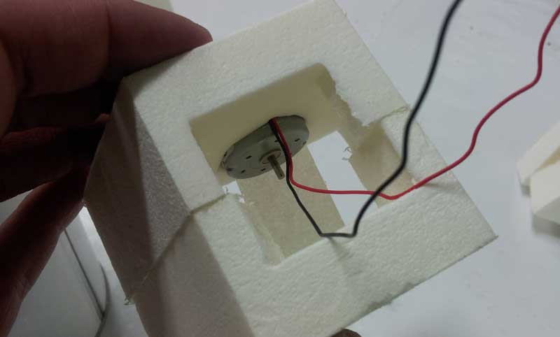
I forgot to get a place for the dc motors inside the Legs, so i repeat
the feet piece to avoid this mistake.
The DC motors in his finall house:
Controling the robot
My next step was to control with the arcade stick (as seen in the video
before) and make another module to make the control remote, by
bluetooth, wifi or whatever.
The wifi needs an Xbee module, too many expensive for a project like this, so i decide to use a bluetooth conexion between the robot and the controller. After some investigations i find the finally option.....an IR remote controlled robot!!
I found this website explaining how to use an IR reciever to control a led over the arduino
so
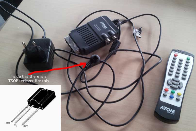
finally i decided to use a recicled Digital TV reciver, which has a
TS22x series IR reciever (dont know exacly wich one) and a remote
control, from where i can control my R2D2 remotely. The only problem is
that i must be in a 45 degrees angle from the reciever to send signal,
but it could be improved later with more Ir recievers around the robot.
With
this reciever you could use any remote to control the robot, just have
to know wich codes send and program it. The pin named OUT sends the
code recieved by the remote control.
To make the IR reciever work with arduino , download this libraries:
Now
upload the code to arduino and open the Serial Monitor (in the
Tools menu). Now if you point the remote control against the IR reciver
and press a button, you can see the code it produces. Each button has
always the same code, so you can use this code to program some action
with this button. In my case, i will use 4 buttons of the remote to
move forward/backward/left and right the robot.
With this way i have solved the
remote control of the robot, and maybe in the future i can use other
buttons from my remote to control other capacities of the robot.
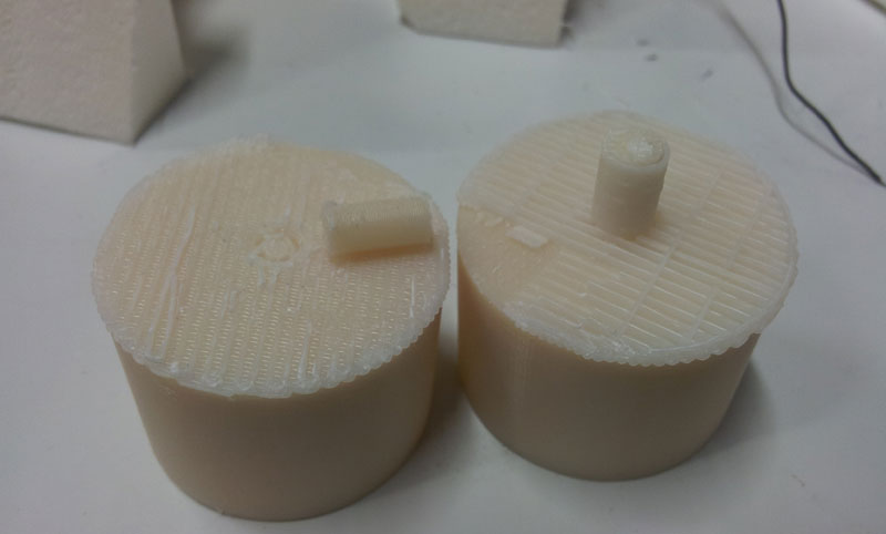
After this i try
to print in the 3d printer the wheels of the R2D2. The axis of the
motor has 2 mm width, so i had to make a ver small piece. As small than
its so easier to brake the axis that i had already did it 2 times.
The printed wheels has a very weak axis, and broked several times. Maybe is a 3D design problem, but i could fix it with acetone.