Week 4 – Embedded Programming
Fab Academy – Week 4
Date range: 11 - 17 Feb
Instructor: Neil
🧠 Learning Objectives
- Implement programming protocols.
📋 Assignments
Individual Assignment
- Browse through the datasheet for a microcontroller
- Write and test a program for an embedded system using a microcontroller to interact (with local input &/or output devices) and communicate (with remote wired or wireless connections)
Group Assignment
- Demonstrate and compare the toolchains and development workflows for available embedded architectures
- Document your work to the group work page and reflect on your individual page what you learned
🛠️ Tools & Materials
- Software (TinkerCAD circuit simulation, Gemini for coding assistance, Wokwi)
- A digital Multimeter
👥 Group Assignment
The objective of the group assignment was to understand and compare the different toolchains for different Microcontrollers. I chose the Pi Pico, and my lab partner chose the esp32-S3
RP2040 Architecture
The Raspberry Pi Pico is based on the RP2040, a dual-core 32-bit ARM Cortex-M0+ microcontroller running at up to 133 MHz. It uses a RISC architecture and includes 264 KB SRAM, external flash memory, USB support, GPIO, UART, SPI, I²C, PWM, ADC, and Programmable I/O (PIO) blocks for creating custom digital interfaces.

From studying the RP2040 architecture diagram, I learned how the different components of the microcontroller are interconnected. The diagram showed that the RP2040 uses two ARM Cortex-M0+ cores that share memory and peripherals, allowing tasks to run in parallel. I also learned that the Programmable I/O (PIO) blocks are separate from the CPU cores, enabling custom communication protocols without heavily loading the processor. The diagram helped me understand the flow of data between the processor, memory, and peripherals such as GPIO, UART, SPI, I²C, ADC, and USB, giving me a clearer picture of how software interacts with hardware in an embedded system.
What is toolchain in embedded system
An embedded system toolchain is a set of software tools; compiler, assembler, linker, and debugger, that converts source code into machine code for a specific target processor. (source)
Key Components of a toolchain
- Compiler It translates high-level programming languages, like C or C++, into assembly code or machine code specific to the target microcontroller's architecture (ARM Cortex, RISC, CISC).
- Assembler The assembler translates low-level assembly language code into machine-readable object code (binary format).
- Linker The linker combines various object files, libraries, and startup code into a single, executable binary file.
The Toolchain Workflow
The toolchain follows a sequence where the Compiler turns code to assembly, the Assembler turns assembly to object code, and the Linker turns object code into a final binary, which is then Flashed (transferred or copied) to the target embedded system.
There are two main ways the Pi Pico processes instructions:
- Interpreted: by using a language like MicroPython/CircuitPython where a "translator" lives on the chip. You send text files, and the chip reads them line-by-line.
- Compiled: by using a language like C/C++ via Arduino or Pico SDK where your computer translates the code into a binary file then send the finished "machine code" to the chip.
The IDEs (Integrated Development Environment)
For the Pi Pico, the comparison is:
- Thonny for MicroPython
- Arduino IDE for C++, later I will explain how I used this option.
- VS Code with the Pico SDK or the PlatformIO IDE extension.
The Raspberry Pi Pico Uses a 32-bit ARM Cortex architecture, I chose to go with the Arduino IDE.
🧪 Process & Workflow (Individual Assignment)
Part 1 – Reading through datasheets
Since my final project will require the use of Bluetooth communication and addressable LED strips. I will be using Xiao Esp32-S3 and WS2812/WS2813 LED strip, I might also use an OLED display.
So, I had to look into the datasheet to understand how these components can interact with each other and restrictions I might have.
The Datasheets
- Microcontroller: Seeed Studio ESP32-S3 Series Datasheet
- LED Strip: WS2812B Datasheet
- OLED Display: SSD1306 (I2C) Datasheet
What I need to focus on in the Datasheet:
The datasheets are comprised of so many pages, so I needed to understand what to look for before starting, and here’s what I found out (with some help from Gemini):
A. Power Requirements:
- Operating Voltage: The Esp32-s3 datasheet specifies a range of 3.0V to 3.6V. I must ensure my power regulator provides a stable 3.3V.
- Current Consumption: During RF (Bluetooth) transmission, the chip can spike up to 355mA. My power supply must be rated for at least 500mA to account for these peaks.
-
A single WS2812B pixel contains three tiny LEDs: Red, Green, and Blue. According to the datasheet, each color channel draws approximately 20mA (60mA for three LEDs) at maximum brightness.
To find the total maximum current for a 10 LEDs:
10×60mA=600mA (or 0.6A)
B. Pinout & multiplexing
Pinout defines the physical location and fixed purpose of each leg on the chip, while multiplexing (via the GPIO Matrix) allows to internally reroute almost any hardware function to almost any digital pin.
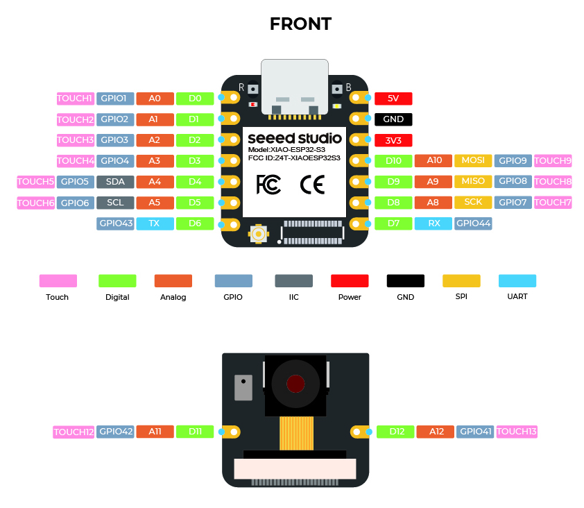
- Strapping Pins: I identified pins GPIO 0, 3, 45, and 46 as strapping pins. I will avoid using these for the OLED or LED data to ensure the chip boots correctly, these pins are reserved for some initial configuration upon startup.

C. Communication Protocols
| Peripheral | Protocol | Pin Requirement | Datasheet Note |
|---|---|---|---|
| OLED Display | I2C (IIC) | SDA/SCL | Supports up to 400 Kbit/s (Fast Mode). |
| LED Strip | Single-Wire | Data In (DI) | Requires 5V logic level; ESP32-S3 is 3.3V. |
| Bluetooth | 2.4GHz | Internal | Uses shared SRAM; memory management is key. |
D. What I Learned from Reading the Datasheets
Power Budgeting is Critical
Before reading the datasheets, I assumed that powering 10 LEDs would not significantly affect the circuit. By calculating the maximum current consumption of the WS2812B LEDs (600 mA for 10 LEDs at full brightness) and comparing it to the ESP32-S3 power requirements, I learned that power budgeting must be considered early in the design process. This helped me understand why many LED projects require a dedicated power supply rather than relying only on USB power.
Not All GPIO Pins Are Equal
I learned that although the ESP32-S3 offers many GPIO pins, some pins have special functions such as strapping pins used during boot. This taught me that selecting pins is not only about availability but also about understanding hardware constraints that can affect system startup and reliability.
Multiplexing Makes Hardware More Flexible
The GPIO Matrix architecture of the ESP32-S3 showed me that communication peripherals such as I²C, SPI, and UART are not fixed to specific pins. I learned that many functions can be reassigned through software, giving more flexibility when designing custom PCBs.
Voltage Compatibility Matters
While reviewing the WS2812B datasheet, I learned that communication between devices is not only about using the correct protocol but also ensuring compatible voltage levels. Since the ESP32-S3 operates at 3.3 V and the LED strip is designed for 5 V operation, I became aware of potential signal integrity issues and the possible need for a level shifter.
Datasheets Help Prevent Design Mistakes
One of the biggest lessons I learned is that datasheets are not only reference documents but also design tools. By checking electrical characteristics, pin functions, and communication requirements before building the circuit, I can identify potential problems early and avoid redesigning the hardware later.
Part 2 – Simulating a grid of 6x6 NeoPixel
In this trial, I explored simulating a 6×6 NeoPixel grid using Tinkercad to test LED animation logic as I plan to do this for my final project. I used Arduino before but never with an LED strip, so I wanted to get more familiar on how do that and create an animated light display.
Gemini Prompt:
I want to make a 6x6 NeoPixel grid in Tinkercad and simulate waves on it. Can you create a flowing rainbow wave animation for it, assuming the strip is wired straight left-to-right row by row?
There were two key functions I found interesting, and had to explore more:
-
setPixelColor(index, r, g, b)Which sets the LED color in buffer memory only
-
strip.show()Which sends the updated color data to the LED strip and actually show it
The 6×6 grid was wired left-to-right, row by row, as shown below:
Row0:0 1 2 3 4 5
Row1:6 7 8 9 10 11
Row2:12 13 14 15 16 17
Row3:18 19 20 21 22 23
Row4:24 25 26 27 28 29
Row5:30 31 32 33 34 35
To convert 2D coordinates into the correct LED index, this function was generated, it takes the needed row and column numbers and returns the led’s number on the strip:
intgetLEDIndex(int row,int col) {return row *6 + col;}
Full Code to Make a flowing rainbow wave on 6x6 led grid
#include<Adafruit_NeoPixel.h>
#define LED_PIN 6
#define NUM_LEDS 36
#define ROWS 6
#define COLS 6

Adafruit_NeoPixel strip(NUM_LEDS, LED_PIN, NEO_GRB + NEO_KHZ800);

void setup() {
  strip.begin();
  strip.show(); // Initialize all LEDs off
}
// Function to map row and column to LED index
int getLEDIndex(int row,int col) {
return row * COLS + col;
}
// Simple color wheel function: 0-255 → rainbow
uint32_t Wheel(byte WheelPos) {
  WheelPos =255 - WheelPos;
  if (WheelPos <85) {
  return strip.Color(255 - WheelPos *3,0, WheelPos *3);
  }elseif (WheelPos <170) {
    WheelPos -=85;
    return strip.Color(0, WheelPos *3,255 - WheelPos *3);
  }else {
    WheelPos -=170;
    return strip.Color(WheelPos *3,255 - WheelPos *3,0);
  }
}
void loop() {
static int offset =0; // controls wave movement
for (int row =0; row < ROWS; row++) {
    for (int col =0; col < COLS; col++) {
      // Create wave effect by combining row, col, and offset
        int colorIndex = (row *16 + col *16 + offset) %256;
        int ledIndex =getLEDIndex(row, col);
        strip.setPixelColor(ledIndex,Wheel(colorIndex));
    }
  }

  strip.show();
  delay(100); // speed of the wave
  offset += 8; // move the wave forward
}
The code successfully produced a smooth diagonal rainbow wave flowing across the 6×6 grid as in the video:
Part 3 – Programming an actual board
After getting warmed up, it was time to test an actual board, I wanted to test something different than what I’ll be using in the final project, so I chose a RaspberryPi Pico, with an RGB Led and made it change it’s color gradually.
1. Building the circuit
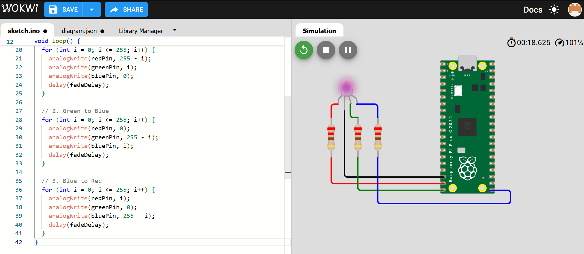
I built the circuit on a simulation tool Wokwi to test the code and the connections before the actual implementation.
I got some help from Gemini:
I will use a RaspberryPi Pico board to make an RGB led change color gradually over a 10 seconds, show me how to connect the circuit and generate the code.
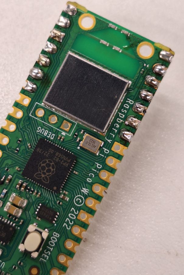
I needed to study the pinout on the RP Pico so I can make the correct wiring.
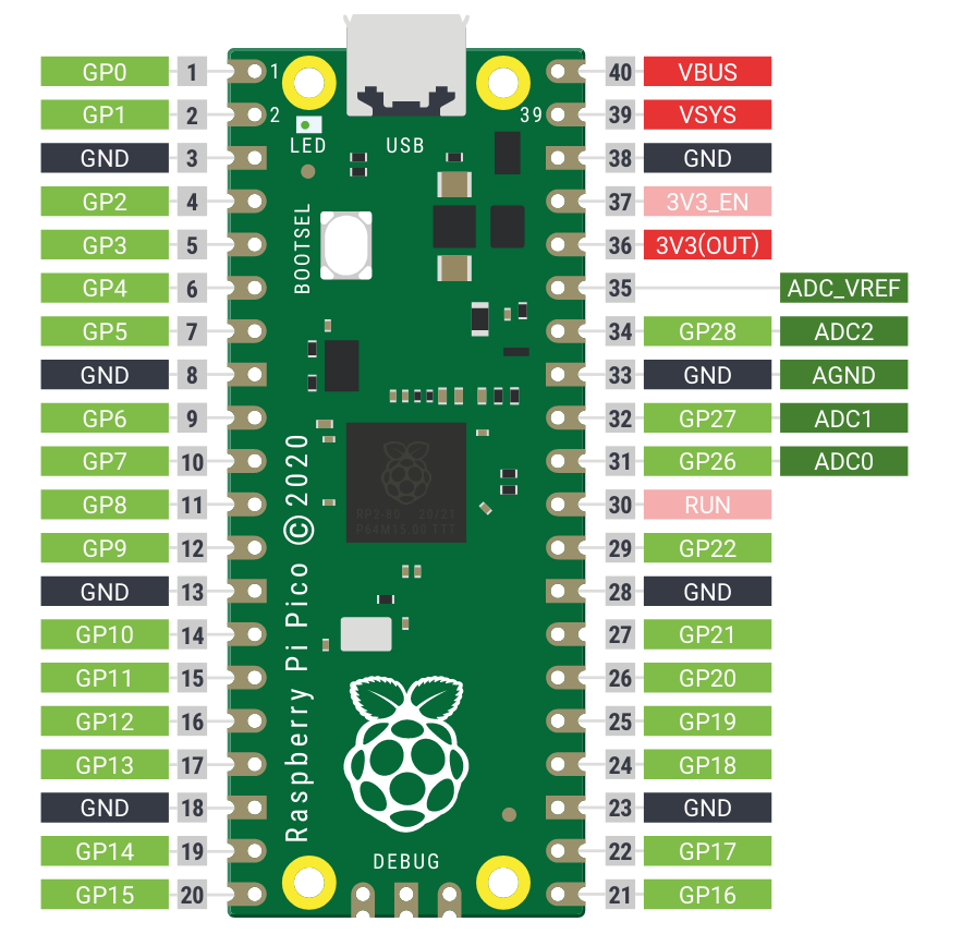
Pi Pico Pinout
This is how it looked on Wokwi simulator:
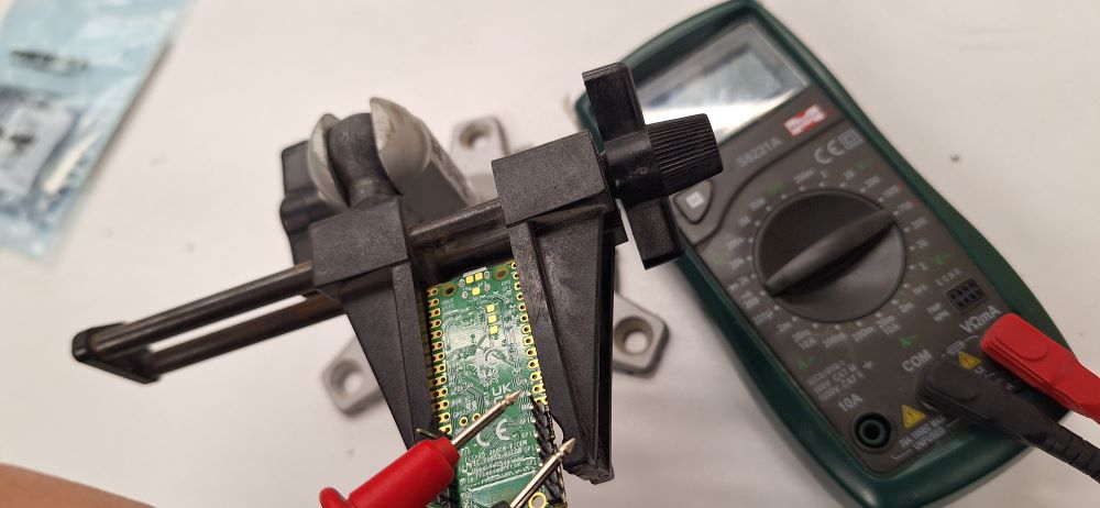
Now it’s time for the real wiring, I decided to use jumper wires and a breadboard. First, I soldered the pins.
Soldering closeup
Then I used a multimeter to check that pins didn’t get connected with the solder.
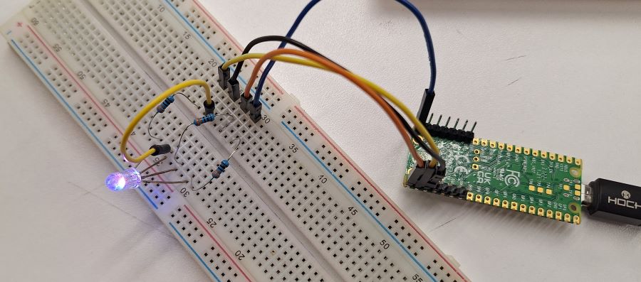
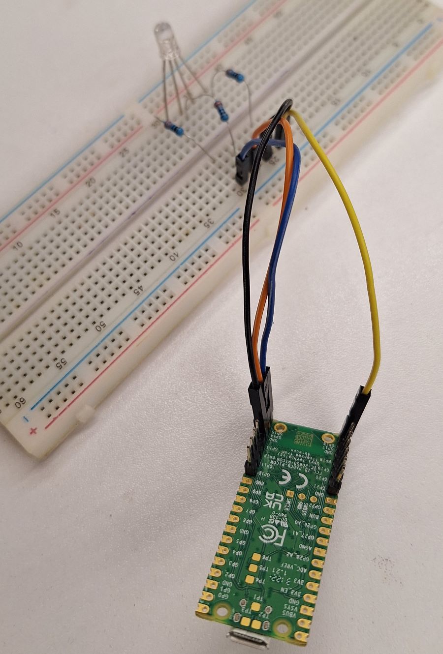
Finally the full circuit.
2. Set up the Arduino IDE for Pico
Here are the steps I followed:
- In Arduino IDE go to File > Preferences.
- In the Additional Boards Manager URLs field, paste this link:
https://github.com/earlephilhower/arduino-pico/releases/download/global/package_rp2040_index.json(If you already have a link there, just add a comma and then paste this one.) - Go to Tools > Board > Boards Manager.
- Search for "Pico" and install the one titled "Raspberry Pi Pico/RP2040" by Earle Philhower.
3. Upload the code and run
Linked using a micro USB cable the Gemini-generated code was compiled then uploaded to the Pi Pico board.
// Define GPIO pins for the Pico
const int redPin = 14;
const int greenPin = 15;
const int bluePin = 16;

void setup() {
  pinMode(redPin, OUTPUT);
  pinMode(greenPin, OUTPUT);
  pinMode(bluePin, OUTPUT);
}

void loop() {
  // We have 3 transitions (R->G, G->B, B->R).
  // 10,000ms total / 3 transitions = 3,333ms per transition.
  // 3,333ms / 255 steps = ~13ms delay.

  int fadeDelay = 13;

  // 1. Red to Green
  for (int i = 0; i <= 255; i++) {
    analogWrite(redPin, 255 - i);
    analogWrite(greenPin, i);
    analogWrite(bluePin, 0);
    delay(fadeDelay);
  }

  // 2. Green to Blue
  for (int i = 0; i <= 255; i++) {
    analogWrite(redPin, 0);
    analogWrite(greenPin, 255 - i);
    analogWrite(bluePin, i);
    delay(fadeDelay);
  }

  // 3. Blue to Red
  for (int i = 0; i <= 255; i++) {
    analogWrite(redPin, i);
    analogWrite(greenPin, 0);
    analogWrite(bluePin, 255 - i);
    delay(fadeDelay);
  }
}
The final result
I couldn’t find a 220ohm, so I used 330ohm which made the light a bit dim.
⚠️ Problems & Solutions
- On Wokwi, when I tested the board nothing happened, then I realised I had to change the long pin on the RGB LED from Anode to Cathode.
📊 Results
- No measurements this week
🧩 Files
📝 Reflection
- Simulating the board is always a good idea, and it saves time on debugging.
- I need to work more on my soldering skills.