Week 15 – Interface and Application Programming
Fab Academy – Week 15
Date range: 29 Apr - 5 May
Instructor: Neil
🧠 Learning Objectives
- Implement a User Interface (UI) using programming and explore protocols to communicate with a microcontroller board that you designed and made.
📋 Assignments
Individual Assignment
Write an application for the embedded board that you made. that interfaces a user with an input and/or output device(s)
Group Assignment
- Compare as many tool options as possible.
- Document your work on the group work page and reflect on your individual page what you learned.
🛠️ Tools & Materials
- Software (Fusion 360 (Animation Workspace), FFmpeg, ImageMagick, and Inkscape.)
- Hardware (Xiao ESP32-C3 Microcontroller, Potentiometer)
- Materials
👥 Group Assignment
The objective of the group assignment was to understand and compare different interface and application programming languages. Link to the group page.
🧪 Individual Assignment
For this week's assignment, I built a web-based Human-Machine Interface (HMI) that allows users to interactively inspect a 3D teardown of my final project using a physical control dial.
Turning a physical potentiometer attached to my custom ESP32-C3 board acts as a manual scrub bar, triggering a smooth, real-time 22-frame "exploding view" animation of my device on screen.
System Architecture & Data Path
The communication pipelining operates via five specific layers:
1. Input Layer: A physical potentiometer outputs an analog voltage drop to GPIO 3.
2. Firmware Layer: The ESP32-C3 converts this analog signal into a stable 12-bit digital range (0–4095).
3. Transmission Layer: The digital string is pumped out via a USB Serial bus at 115,200 baud.
4. Bridge Layer: A native p5.serialcontrol WebSocket server captures the local serial port data stream and broadcasts it locally via WebSockets on port 8081.
5. Application Layer: A p5.js app running inside the browser receives the socket packets, maps the value to an array index, and renders the corresponding slice of a high-resolution sprite sheet.
A physical knob controls a web-based “exploded visualization” of my final project, showing labels at certain positions to explain what the product looks like from outside and inside.
To achieve this I’m making what it’s called scroll scrubbing, the best and most straightforward way to implement this is by using an image sequence or sprite sheet, which will be controlled by potentiometer through a WebSerial API using the USB connection with ESP32-C3
WebSerial + p5.js + image-sequence scrubbed by potentiometer on a PCB with a ESP32-C3
Process & Workflow
Step 1 – Preparing the Sprite Sheet
I used Fusion 360’s Animation workspace to make a video of imploding parts of my device as a storyboard. Then exported the animation as a video, sliced it into multiple images using ffmpeg then created the sprite sheet using Inkscape.
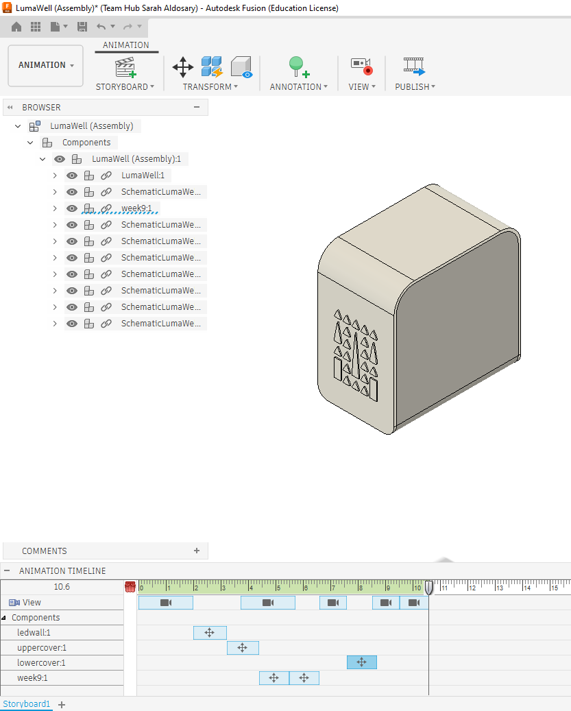
When I was satisfied with the transition, I published the video as an AVI of 16:9 resolution.
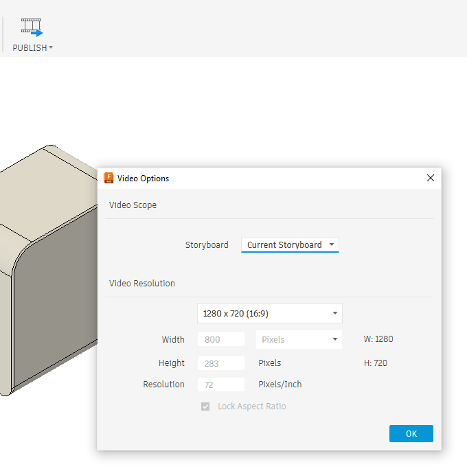
Then I used ffmpeg to slice the video to images using the following command, fps=2 means two images per second:
ffmpeg -i LumaWell.avi -vf fps=2 out%d.png
My video was 11seconds, so I ended up with 22 png files.
Sprite Sheets
Sprite sheet is a cleaver way to combine multiple images into one so the page can load once, instead of loading each image as it’s needed. This is convenient for my case as I wanted to move through these images seamlessly.
There are many ways you can make the sprite sheet, there are tools online and you can also use ImageMagick. For me Inkscape was the most straightforward, I calculated the document size in inkscape based on the size of the png’s (22x1280=28160px as width, 720px as height) then stacked the images next to each other:
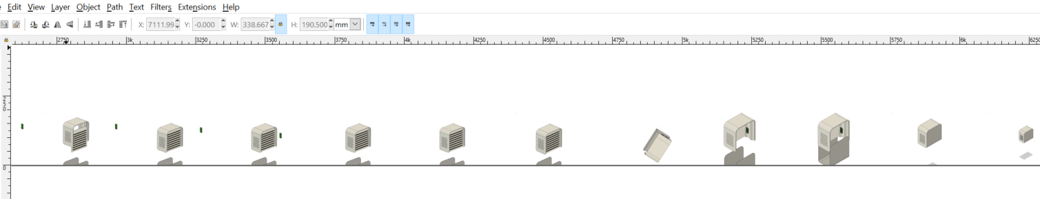
Finally, export the Inkscape page as png.
Step 2 – The Hardware
I am using an ESP32-C3 here, and inorder
Here is the code to read the values, but before uploading ensure Tools > USB CDC On Boot is Enabled (this is vital for the C3 to talk to the computer).
/*
  Fab Academy Week 15: Potentiometer to p5.js
  Board: ESP32-C3
  Pin: GPIO 3 (ADC1_CH3)
*/

const int potPin = 3;

void setup() {
  // Higher baud rate for smoother animation frame rates
  Serial.begin(115200);

  // The C3 sometimes needs a second to initialize USB Serial
  while (!Serial);

  pinMode(potPin, INPUT);
}

void loop() {
  // Read the potentiometer (Value will be 0 - 4095)
  int val = analogRead(potPin);

  // Send the value followed by a newline for the Serial Bridge
  Serial.println(val);

  // Small delay (approx 30-60 fps) to prevent flooding the serial buffer
  delay(20);
}
Verification:
- Open the Serial Monitor in Arduino IDE.
- Set the baud rate to 115200.
- Turn your potentiometer. You should see a column of numbers scrolling down.
- Close the Serial Monitor. (If you don't close it, the p5.serialcontrol app won't be able to connect to the port).
Step 3 – The software
p5.js sketch:
let serial;
let potValue = 0;
let spriteSheet;
let totalFrames = 22;
let frameWidth, frameHeight; // Original dimensions
let displayWidth, displayHeight; // Scaled dimensions
let imgLoaded = false;
function preload() {
// Use the direct URL to my FabCloud image
spriteSheet = loadImage('https://fabacademy.org/2026/labs/vujade/students/sarah-aldosary/images/assembly_sprites.png',
() => { imgLoaded = true; },
() => { console.log("Failed to load image"); }
);
}
function setup() {
// 1. Create a canvas that fills the whole browser window
createCanvas(windowWidth, windowHeight);
serial = new p5.SerialPort();
serial.open("COM11");
serial.on('data', serialEvent);
imageMode(CENTER);
rectMode(CENTER); // We need this for the frame
}
// 2. This handles window resizing smoothly
function windowResized() {
resizeCanvas(windowWidth, windowHeight);
}
function draw() {
// Background color - a clean light gray
background(240);
if (imgLoaded) {
// Original Frame Size (Width / 22)
frameWidth = spriteSheet.width / totalFrames;
frameHeight = spriteSheet.height;
// 3. Dynamic Scaling (Keep in the center)
// We want the image to fill 80% of the screen height, maintaining aspect ratio
displayHeight = height * 0.8;
displayWidth = displayHeight * (frameWidth / frameHeight); // Maintain 16:9 ratio
let frameIndex = floor(map(potValue, 0, 4095, 0, totalFrames - 1));
frameIndex = constrain(frameIndex, 0, totalFrames - 1);
// Draw the image scaled to our calculated display size
image(spriteSheet, width/2, height/2, displayWidth, displayHeight,
frameIndex * frameWidth, 0, frameWidth, frameHeight);
// 4. Draw a nice Frame
noFill();
stroke(50); // Dark gray border
strokeWeight(10); // Nice thick border
rect(width/2, height/2, displayWidth, displayHeight, 5); // Added slight corner radius (5)
// Optional: Label
noStroke();
fill(50);
textAlign(CENTER);
textSize(16);
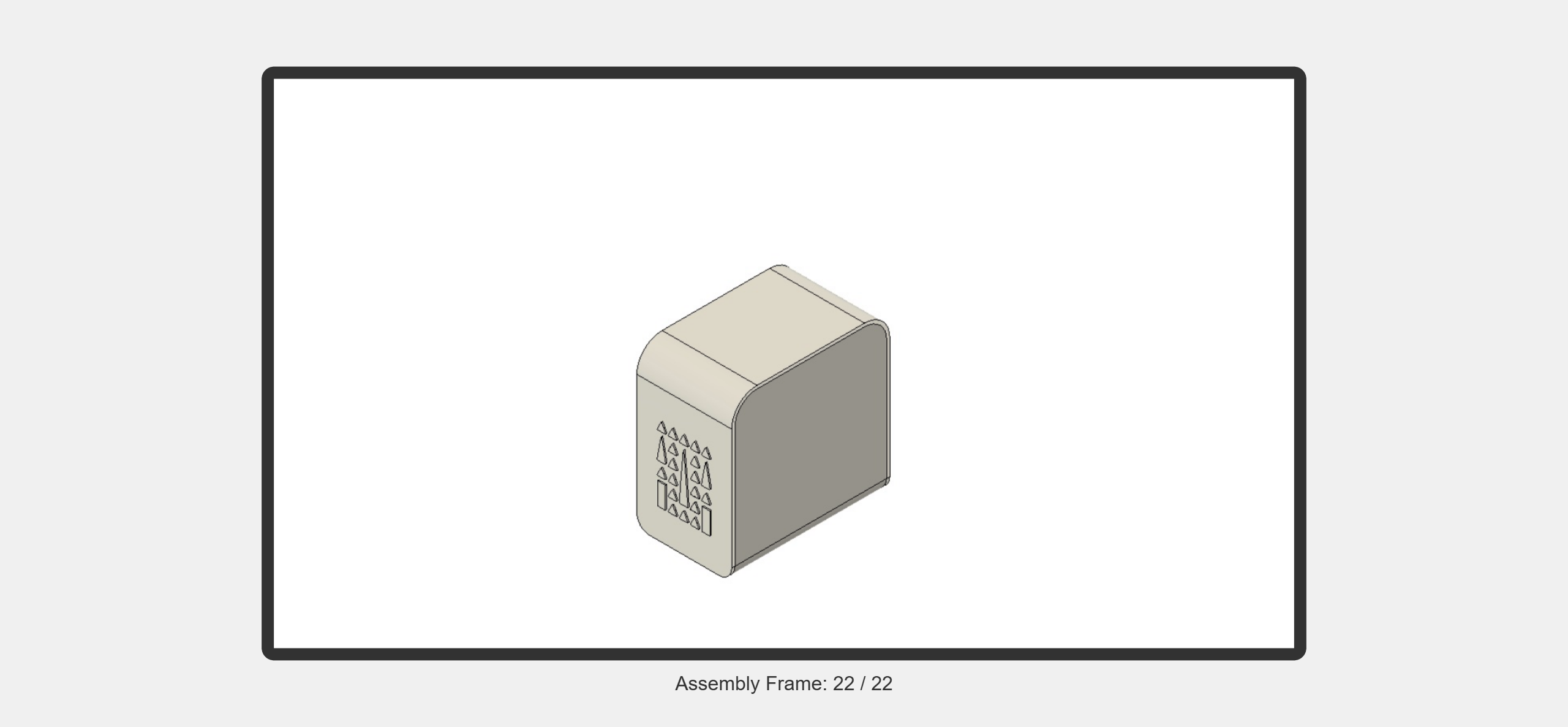
text("Assembly Frame: " + (frameIndex + 1) + " / 22", width/2, height - 30);
} else {
// Loading indicator
noStroke();
fill(0);
textAlign(CENTER);
textSize(24);
text("Downloading Assembly Sprites...", width/2, height/2);
}
}
function serialEvent() {
let data = serial.readLine();
if (data.length > 0) {
potValue = Number(trim(data));
}
}
The html file:
<!DOCTYPE html>
<html lang="en">
  <head>
    <meta charset="utf-8" />
    <meta name="viewport" content="width=device-width, initial-scale=1.0">

    <title>Fab Academy Week 15: Sprite Animation</title>

    <!-- p5.js Core Library -->
    <script src="https://cdnjs.cloudflare.com/ajax/libs/p5.js/1.9.0/p5.js"></script>

    <!-- p5.serialport Library - Required for communicating with the bridge app -->
    <script src="https://cdn.jsdelivr.net/npm/p5.serialserver@0.0.28/lib/p5.serialport.js"></script>

    <style>
      body {
        padding: 0;
        margin: 0;
        background-color: #f0f0f0;
        overflow: hidden; /* Prevents scrollbars */
      }
      canvas {
        display: block;
      }
    </style>
  </head>

  <body>
    <!-- Your p5.js logic -->
    <script src="sketch.js"></script>
  </body>
</html>
Project Overview
For this week, I developed a web-based Human-Machine Interface (HMI) using p5.js to interact with my Final Project’s physical hardware. The goal was to create a "Scrubbable Assembly View": turning a potentiometer on my ESP32-C3 board would trigger a 22-frame "exploding" animation of my project assembly on my laptop screen.
The Workflow
The data travels through the following path:
- Input: Potentiometer (Analog Signal) on GPIO 3.
- Processing: ESP32-C3 converts the signal to a 12-bit digital value (0-4095).
- Transmission: Data is sent via Serial (USB-C) to the computer.
- Bridge: p5.serialcontrol app listens to the serial port and relays data to the browser via Websockets.
- Output: p5.js maps the values to a specific frame of a sprite sheet.
Step 1: Hardware & Embedded Code
I used my custom ESP32-C3 board. I connected a potentiometer to GPIO 3.
The Code:
I set the baud rate to 115200 to ensure smooth communication and used Serial.println() so each value appears on a new line, which is required for the p5.js serial library to read strings properly.
const int potPin = 3;

void setup() {
  Serial.begin(115200);
  while (!Serial);
  pinMode(potPin, INPUT);
}

void loop() {
  int val = analogRead(potPin);
  Serial.println(val);
  delay(20); // Maintain ~50fps
}
Step 2: Preparing the Sprite Sheet
I had a 16:9 video of my final project assembly. I needed to convert this into a single "Sprite Sheet" image.
- Slicing: I used FFmpeg to extract a frame every 0.5 seconds:
ffmpeg -i "LumaWell.avi" -vf "fps=2" frame_%04d.png - Stitching: I used ImageMagick to combine 22 frames into one horizontal strip:
magick montage -mode concatenate -tile 22x1 frame_*.png assembly_spritesheet.png - Optimization: Since the resulting image was massive (over 40,000 pixels wide), I scaled the frames down to a 640px width to prevent the browser from crashing.
Step 3: Building the Interface (p5.js)
The p5.js sketch calculates which "slice" of the sprite sheet to show based on the potentiometer value.
Final Interface Code
The final version includes dynamic scaling to ensure the assembly animation fits the screen perfectly with a clean 10px frame.
JavaScript
function draw() {
  background(240);
  if (imgLoaded) {
    let frameWidth = spriteSheet.width / 22;
    let displayHeight = height * 0.8;
    let displayWidth = displayHeight * (frameWidth / spriteSheet.height);

    let frameIndex = floor(map(potValue, 0, 4095, 0, 21));
    frameIndex = constrain(frameIndex, 0, 21);

    // Display the specific frame from the sheet
    image(spriteSheet, width/2, height/2, displayWidth, displayHeight,
          frameIndex * frameWidth, 0, frameWidth, spriteSheet.height);

    // UI Frame
    noFill();
    stroke(50);
    strokeWeight(10);
    rect(width/2, height/2, displayWidth, displayHeight, 5);
  }
}
🔍 Testing, Debugging, and Proof of Functionality
1. Isolated Hardware Layer Testing
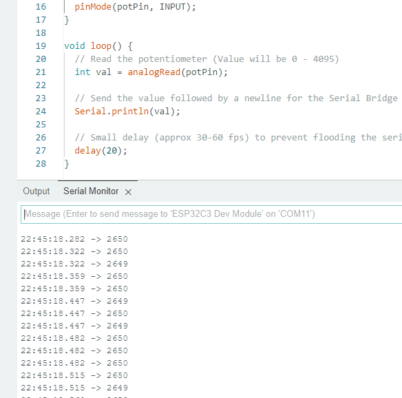
Before connecting my microcontroller to the browser environment, I verified that the physical data path was functioning correctly. I flashed my firmware to the ESP32-C3, opened the Arduino IDE Serial Monitor at 115200 baud, and manually rotated the potentiometer.
The image shows successful hardware testing logging frame. The Serial Monitor records a clean, scrolling column of telemetry values scaling linearly between 0 and 4095 as the dial turns, verifying functional hardware ADC conversion and serial CDC bus configurations.
Important Port Release Rule Identified During Testing: The host computer's operating system locks the serial device port exclusively. I verified that you must actively close out the Arduino Serial Monitor window before launching the web server app; otherwise, the p5.serialcontrol socket application will be thrown a port busy error and block access.
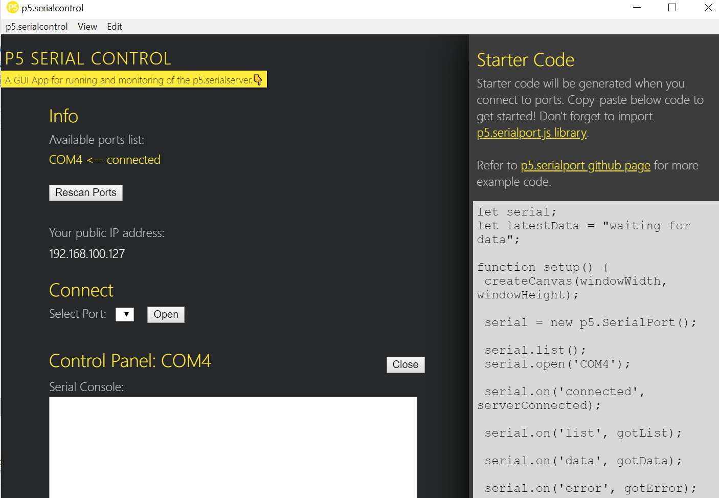
The image shows the p5.serialcontrol opening the port succssfully.
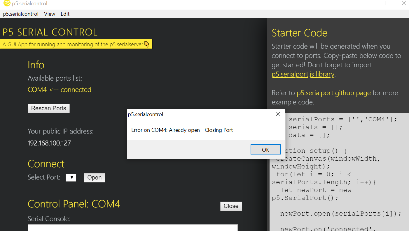
The image shows the p5.serialcontrol failing to open the port becuase it's being used by Ardunio IDE.
2. Runtime Troubleshooting & Engineering Triage
During integration, three distinct software and architectural errors were isolated and successfully resolved:
- Error 1:
Uncaught TypeError: p5.SerialPort is not a constructor- Root Cause Analysis: Inspecting the runtime browser console error messages revealed that the legacy, unmaintained CDN paths were serving broken or uninstantiated library definitions.
- Resolution Action: I updated the script parameters in
index.htmlto target the verified stable production build of thep5.serialserver@0.0.28package.
- Error 2: Cross-Origin Resource Sharing (CORS) Local Asset Blocks
- Root Cause Analysis: When launching
index.htmllocally using standard file scheme flags (file:///), Chrome's native security sandboxing policies strictly block the execution code from fetching local disk assets like my sprite sheet image. - Resolution Action: I bypassed local security sandboxing by pushing the asset file directly to the remote FabCloud production server repository and passed the absolute URL string into the application’s
loadImage()block.
- Root Cause Analysis: When launching
- Error 3: Local Port Sandbox Constraints
- Root Cause Analysis: Modern browsers prevent web scripts from communicating directly with raw computer serial ports without explicit authorization bridges.
- Resolution Action: I deployed the desktop Node-based utility bridge app
p5.serialcontrol. This application acts as a secure local middleman, opening a web-socket server at port 8081 to fetch and packetize incoming serial lines directly into browser memory.
3. Integrated System Proof of Functionality
The end-to-end data pathway is fully functional. The physical manipulation of the potentiometer alters the analog state, transmits numerical data over serial, routes through the websocket server, and enables the user to smoothly control the 3D exploding animation view frame-by-frame on screen.
Figure 2: Final integrated system functionality proof. The video captures my hand turning the physical potentiometer dial on my custom milled PCB development board while the p5.js canvas environment simultaneously decodes the incoming packets to scrub the 3D enclosure explosion animation in real-time.
⚠️ Problems & Solutions
- The Bridge Requirement: I initially tried to connect directly from Chrome, but learned that browsers block direct serial access for security. I had to download and run the p5.serialcontrol app to act as a middleman.
- CORS Error: Chrome blocked my local sprite sheet image when opening the
index.htmlfile directly. I solved this by uploading the image to my FabCloud repository and calling it via an absolute URL. - Library Conflict: I encountered the error
Uncaught TypeError: p5.SerialPort is not a constructor. This was fixed by switching to a more reliable CDN for the library:<script src="[https://cdn.jsdelivr.net/npm/p5.serialserver@0.0.28/lib/p5.serialport.js](https://cdn.jsdelivr.net/npm/p5.serialserver@0.0.28/lib/p5.serialport.js)"></script>
🧩 Files
📝 Reflection
This assignment bridged the gap between my physical electronics and my documentation. By using a potentiometer as a "scrub bar," I created a way for users to interact with my 3D design process rather than just looking at a static image.