Week 17 – Wildcard Week
Fab Academy – Week 17
Date range: 13 May - 19 May
Instructor: Neil Greshenfeld
🧠 Learning Objectives
- Demonstrate workflows used in the chosen process
- Select and apply suitable processes (and materials) to do your assignment.
📋 Assignments
Individual Assignment
- Document the workflow(s) and process(es) you used
- Explain how your process is not covered in other assignments
- Describe problems encountered (if any) and how you fixed them
- Include original design files and source code
- Include ‘hero shot’ of the result
🛠️ Tools & Materials
- Inkscape, OnShape
- Laser cutter, 3D printing
- Acrylic sheet and PLA
🧭 Introduction
This week we are asked to create our own assignment. I can admit that for my final project I tried to play it real safe, and work in spirals that I can handle given my work and busy life. But when this week came I started thinking of ways I can improve my final project and add some kind of complexity. Since my final project is all about calm and wellbeing, and since there’s a feature of guided breathing with lights, I wanted to make it look more alive when guiding me in a breathing session. So the challenge was how do I make my device breathe.
I started exploring and researching mechanical movements that look smooth and can resemble breathing.
I started looking into Iris mechanism (or Iris Diaphragm) and how it can be implemented, it’s the mechanism that opens and shut the camera lens.
https://upload.wikimedia.org/wikipedia/commons/4/48/Iris_Diaphragm.gif?_=20151027125422
I also, thought about making cubes that move in and out following the same mechanism here, but this would require many servos, and they are not quite.
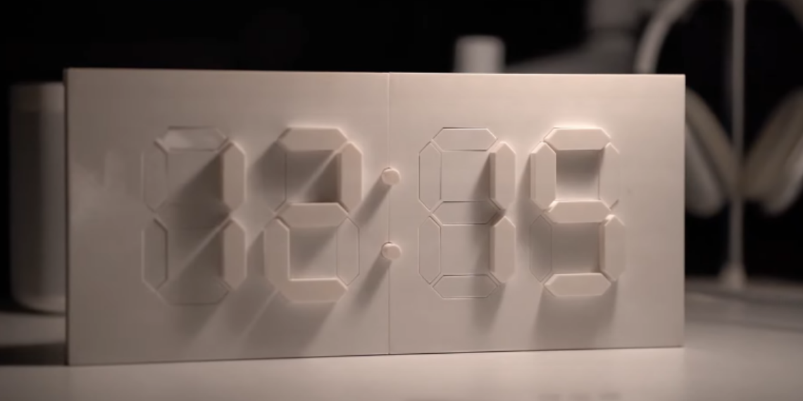
Then I came across this clock, which was mesmerizing, it opens up and closes as time move, it was so smooth and natural that it almost felt alive:
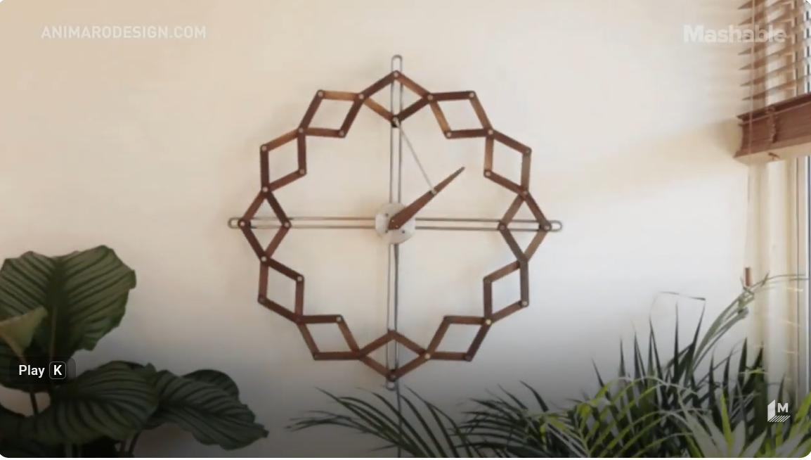
So I decided to give it a try. I found this tutorial on Grasshopper: https://www.youtube.com/watch?v=kdzE6yxsb44
🧪 Process & Workflow
- Process Chosen: Digital Fabrication of a Mechanical Iris / Kinetic Solstice Mechanism.
- The Goal: To scale up the LumaWell final project by adding smooth, mechanical movement to simulate a physical breathing cycle during guided wellness sessions.
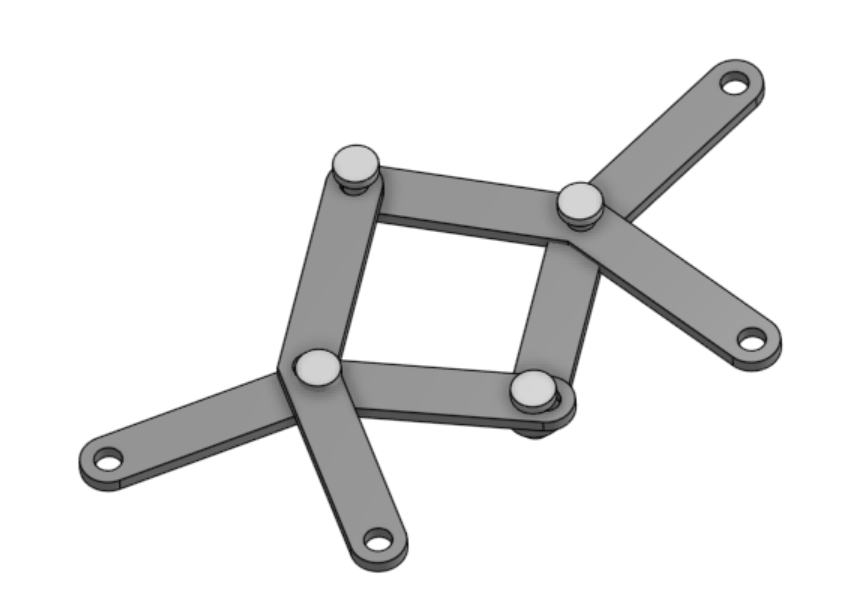
Step 1 – Design (OnShape & Inkscape)
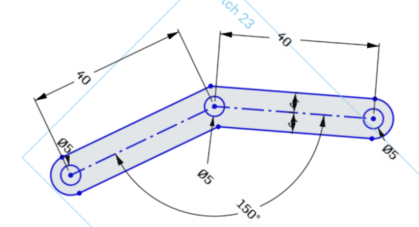
When I started designing the arms, I wasn’t sure what size to use. I looked at the ones on YouTube, took a screenshot, and roughly measured the angle.
I designed it with an angle of 150 degrees
I then designed the joints in two parts. I made 4 of them longer than the others because they are the ones responsible for anchoring the primary arms to the static acrylic back panel.
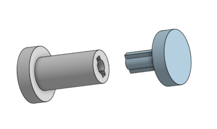
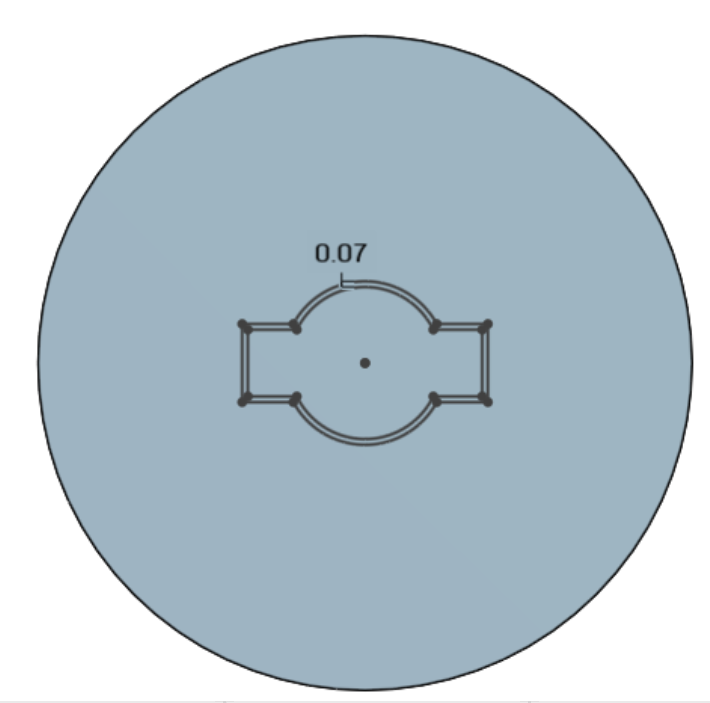
The two halves of each joint are designed to hold together via a very tight mechanical press fit.
Attempting to model the full concentric motion and assembly paths directly in OnShape proved harder and more constrained than expected, so I moved quickly to physical prototyping.
Step 2 – Fabrication (Laser Cutting and 3D Printing)
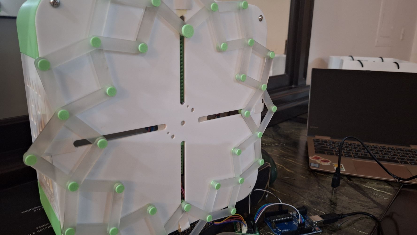
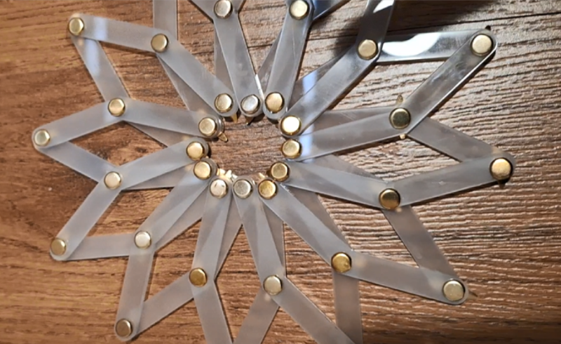
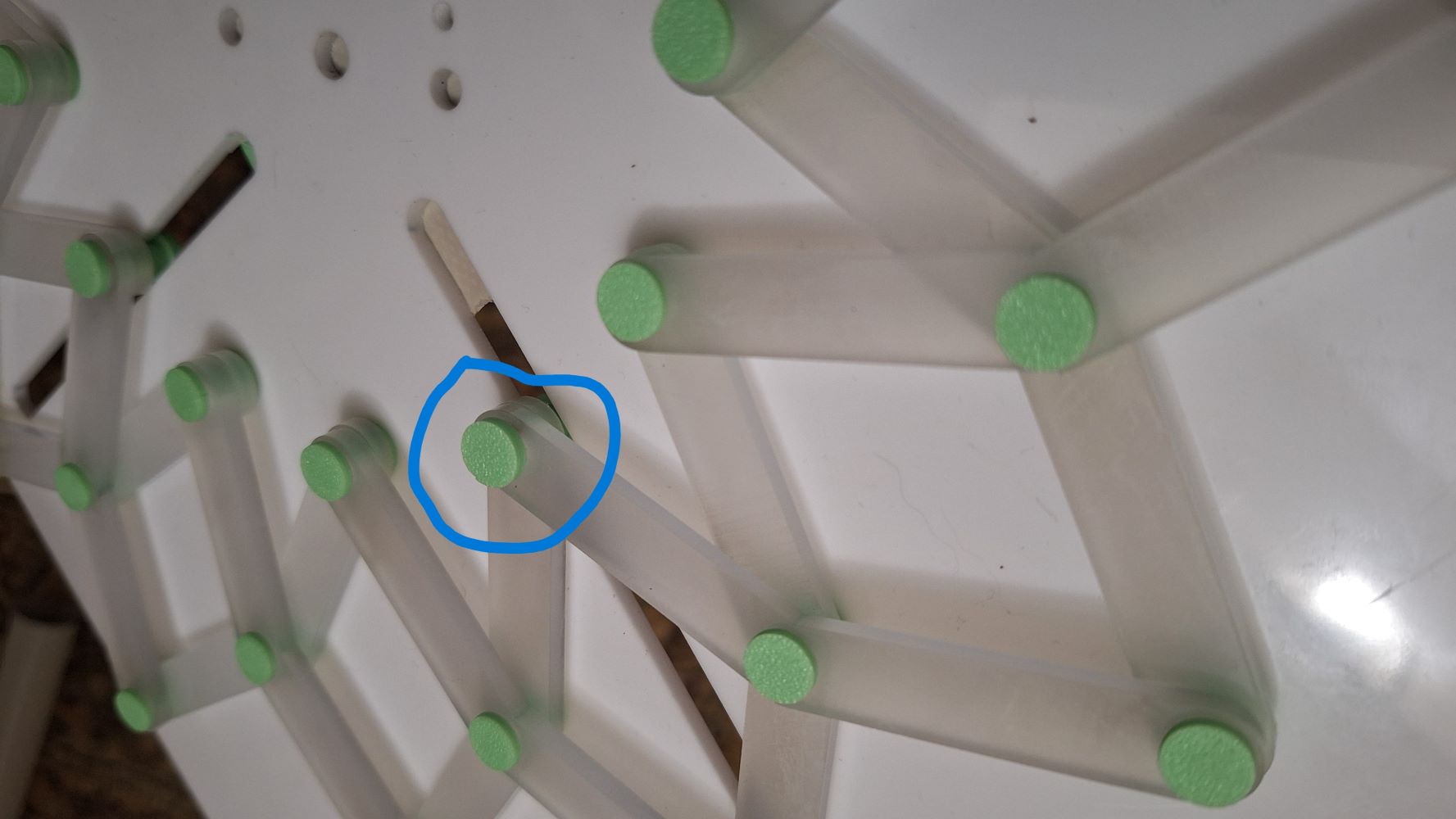
I first cut the arms with the laser cutter and used a metal pins to hold the parts together to see if it’s actually going to work, and did, it was wobbly a bit but the mechanism was successful.
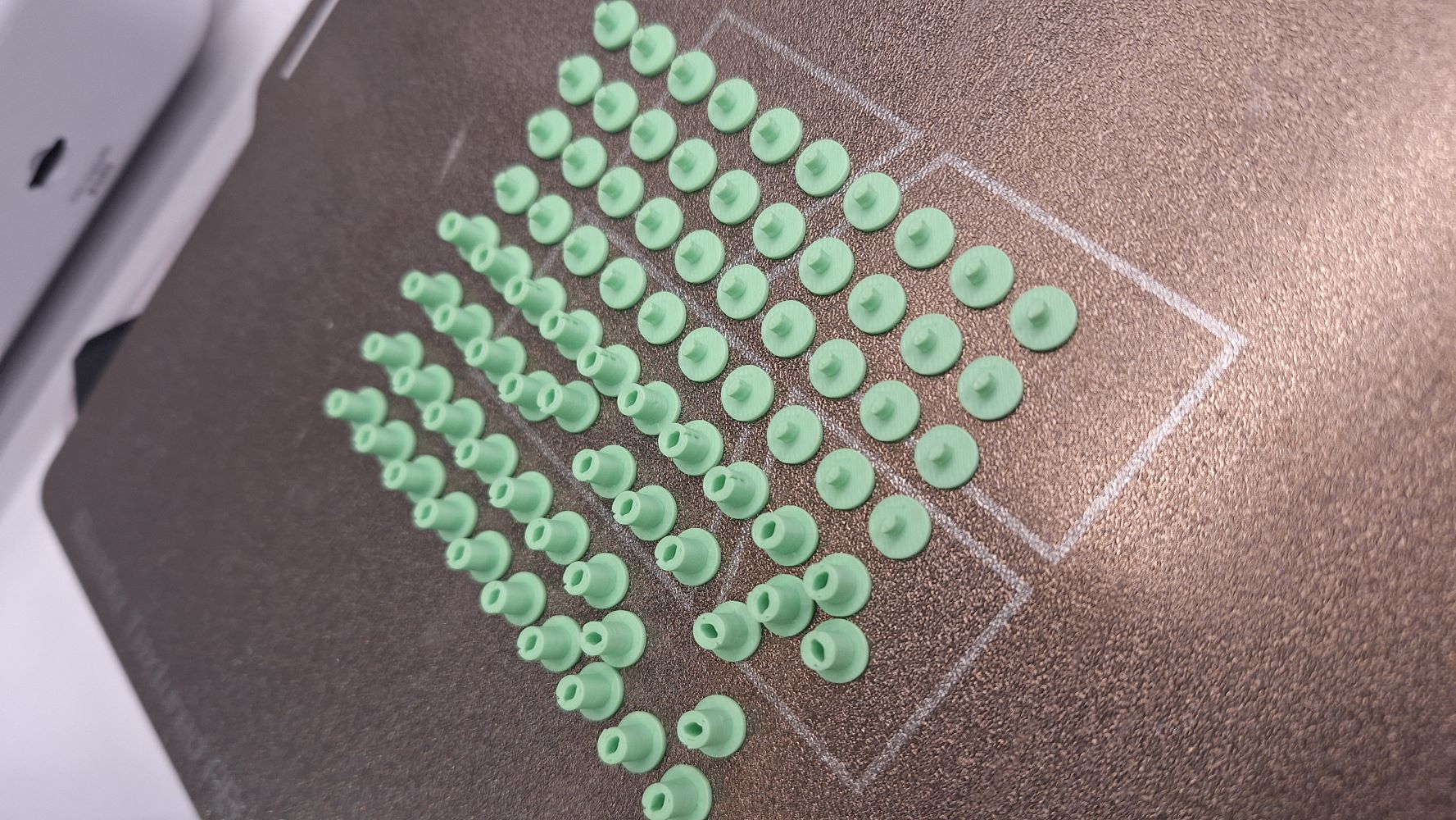
Then I 3D printed the joints with 3D printer.
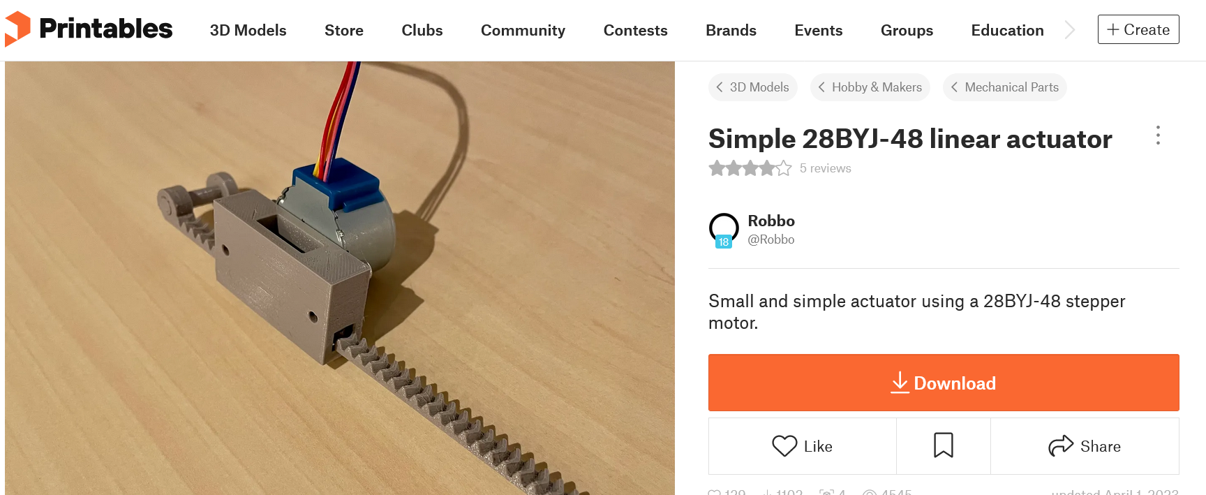
As for the mechanical drive movement, I found an open-source linear gear actuator designed for the 28BYJ-48 stepper motor on printables.com, I printed it expecting to modify it, but surprisingly it worked perfectly out of the box, it even featured an end-pin that mapped directly to my mechanism's driver slot.
Step 3 – Assembly
I started assembling the parts with the 3D printed jionts, then fixed them on the panel with the longer one.
Next, I aligned and assembled the linear actuator mechanism.
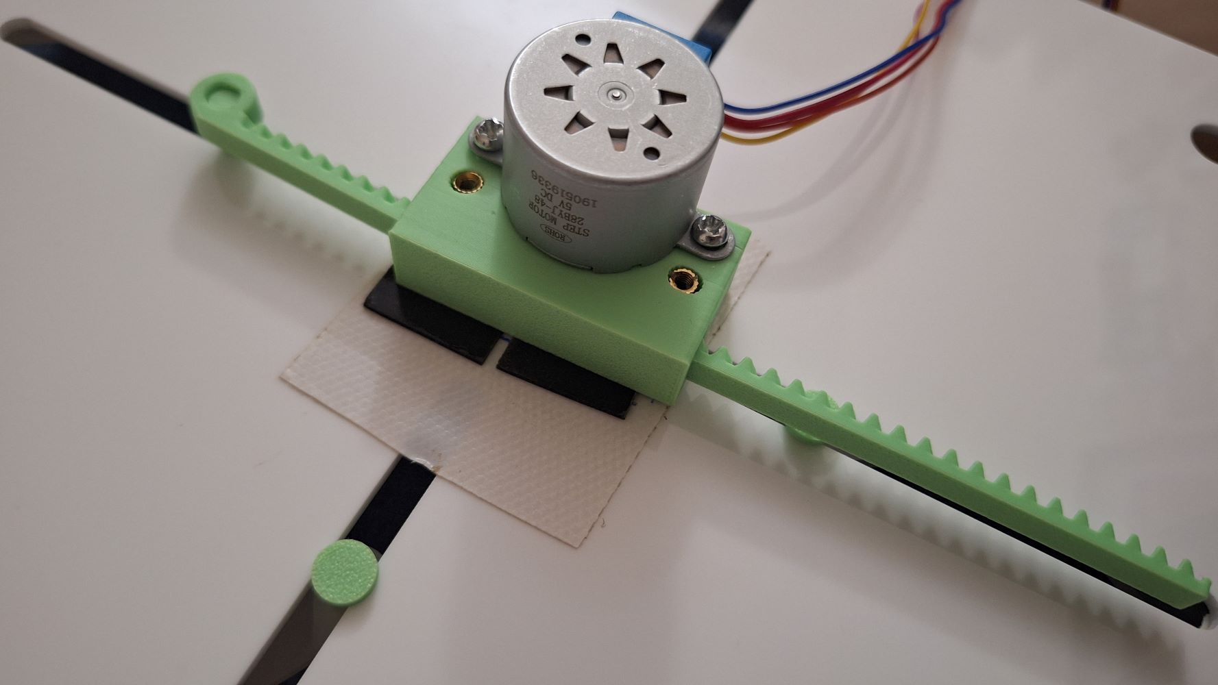
For this rapid prototype iteration, the motor housing is fixed to the back panel using a strong adhesive. For the next design spiral, I will modify the CAD to integrate a modular motor bracket that screws directly into the main panel.
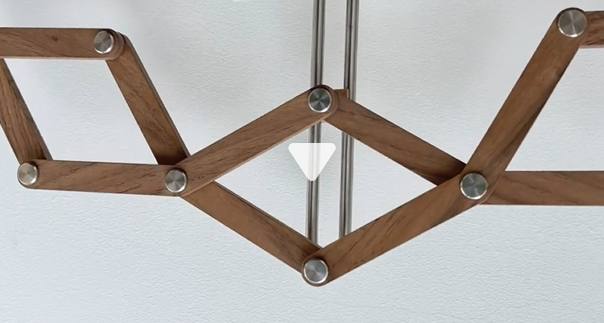
Here's the final result in motion:
The code for actuation:
#include <Stepper.h>

// Number of steps per internal motor revolution
const int stepsPerRevolution = 2048;

// Change this number to adjust your exact physical distance:
// Based on a T8 leadscrew: 5120 steps = 2.5 turns = 2 cm of travel
const int stepsToMove = 5120;

// Initialize the stepper library on pins 8, 9, 10, 11
// Note the pin order change (8, 10, 9, 11) required for the ULN2003 driver
Stepper myStepper(stepsPerRevolution, 8, 10, 9, 11);

void setup() {
  // Set the speed of the motor in RPM (Revolutions Per Minute)
  // The 28BYJ-48 safely runs best between 10 and 15 RPM
  myStepper.setSpeed(12);
}

void loop() {
  // Move 2 cm "Up" (clockwise)
  myStepper.step(stepsToMove);
  delay(1000); // Pause for 1 second

  // Move 2 cm "Down" (counter-clockwise)
  myStepper.step(-stepsToMove);
  delay(1000); // Pause for 1 second before repeating
}
📝 Why This is a "Wildcard" (Not Covered Elsewhere)
- This assignment explores Kinetic Linkage Assemblies and Mechanical Metamaterials (Iris/Solstice structures).
- While previous weeks covered separate production methods (just 3D printing or just laser cutting), this week focuses entirely on the intersection of multi-material mechanical tolerances, overlapping moving joints, and dynamic physical movement to create an expressive interface.
⚠️ Problems & Solutions
- Problem: The 3D printed joint pins ended up slightly smaller than the holes in the laser-cut acrylic arms. This introduced mechanical backlash, making the expansion movement a little bit out of sync (some segments lagged behind before the rest followed).
- Fix: For the next iteration, I will increase the pin diameter by 0.15mm in OnShape to turn it into a true friction-fit, eliminating the slop between the links.