Week 7 - Computer Controlled Machining
Fab Academy – Week 7
Date range: 4-10 Mar
Instructors:
Tony Schmitz,Tom Bodett
🧠 Learning Objectives
- Demonstrate 2D design development for CNC milling production
- Describe workflows and operation for large format CNC machining
📋 Assignments
Individual Assignment
- Make (design+mill+assemble) something big
Group Assignment
- Complete your lab's safety training
- Test runout, alignment, fixturing, speeds, feeds, materials and toolpaths for your machine
- Document your work to the group work page and reflect on your individual page what you learned
🛠️ Tools & Materials
- Software (VCarve, OnShape)
- Machines (X-Carve, Dewalt spindle)
- Materials (plywood 11mm)
👥 Group Assignment
The objective of the group assignment was to understand the operation and limitations of the CNC router in our lab. We performed safety training and tested different machining parameters including runout, alignment, fixturing methods, feeds and speeds, materials, and toolpaths to determine optimal settings for our machine. Personal Protective Equipment (PPE)
- Safety glasses
- Hearing protection
- Closed-toe shoes
- Dust mask when cutting wood
Safety Rules
- Never leave the CNC machine unattended while running.
- Keep hands away from the spindle and cutting area.
- Avoid loose clothing, jewelry, or long hair near moving parts.
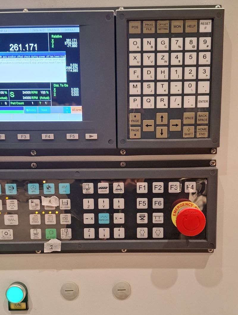
- Ensure the emergency stop button is accessible.
- Secure the workpiece properly before starting the job.
- Turn on the dust collection system before cutting.
- Don’t operate the machine unaccompanied.

Knowing where the emergency stops are before starting any job.
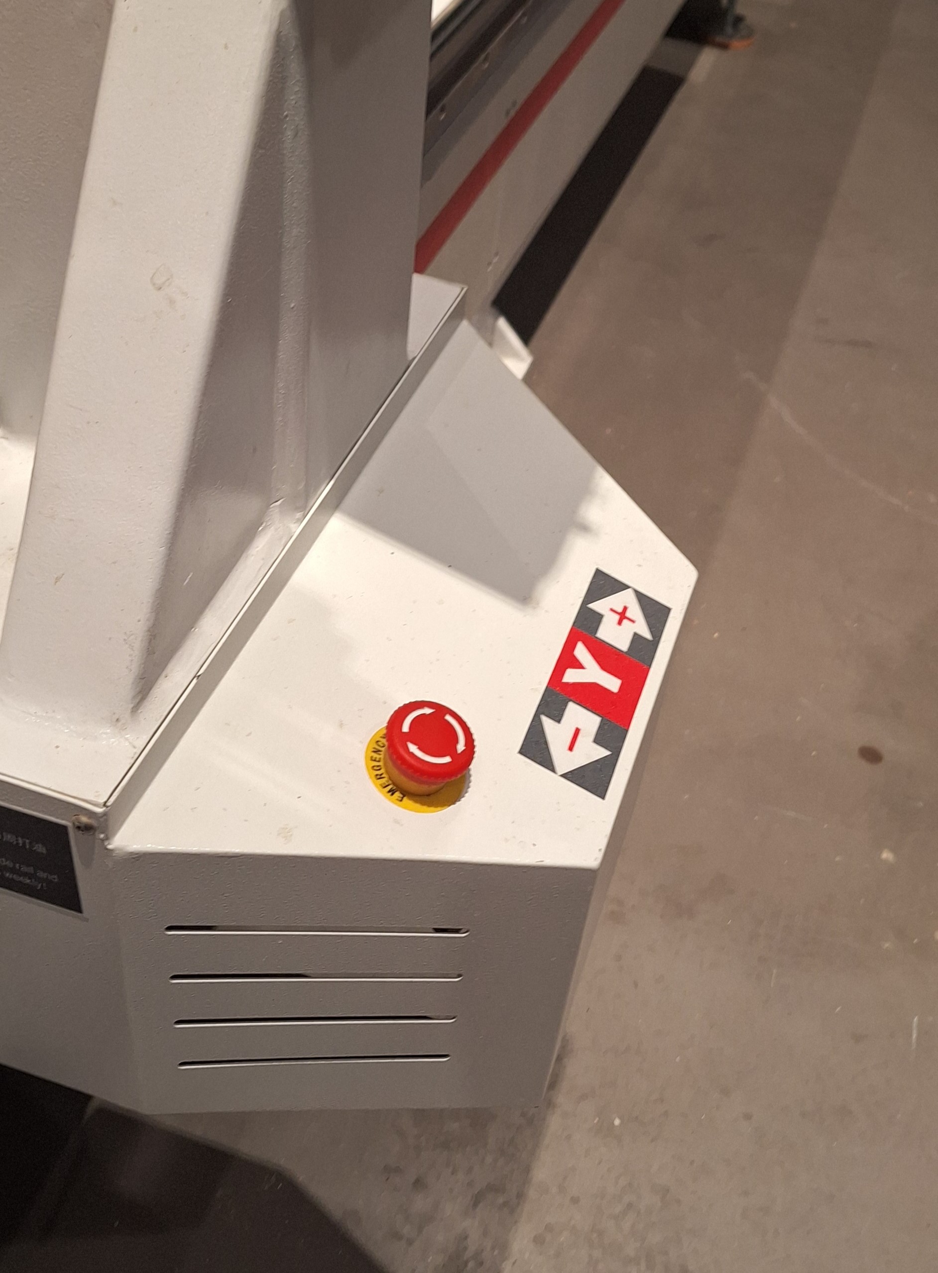
Another one, on the side of the machine:
Machine Setup
1. Tool Installation
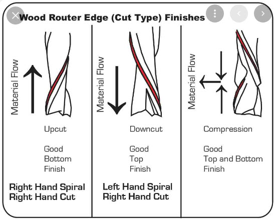
We installed an end mill suitable for cutting plywood. X-Carve sell end mills color coded to make it easier to determine the needed end mill for each project.
Here’s a diagram of an end mill:
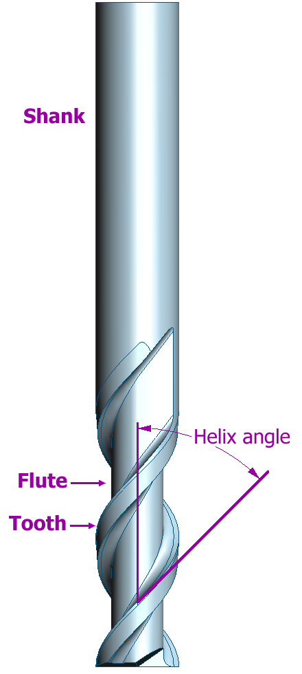
Some of the available end mills:
[placeholder, end mills]
Below is a table of some of the end mills available:
| Ring Color | Type | Cutting Diameter | Cutting Length | Overall Length | Usage |
|---|---|---|---|---|---|
| Purple | 3F Spiral Upcut | 1/8" | 0.30" | 1.57" | Cutting: Plastics, woods, aluminum, soft metals |
| Black | 2F Straight | 1/8" | 0.87" | 1.77" | Cutting: Plastics, woods |
| Gray | 1F Spiral Upcut | 1/8" | 0.87" | 1.77" | Cutting: Plastics, woods, aluminum, soft metals |
| Blue | 2F Fish Tail Upcut | 1/16" | 0.31" | 1.5" | Cutting: Plastics, woods, soft metals, soft materials like linoleum |
| Neon Yellow | 2F Fish Tail Downcut | 1/8" | 0.30" | 1.5" | Cutting: Solid wood and plywood |
Depending on the material you’re cutting you can choose the appropriate cut type:
Steps to load the end mill:
- Loosen the collet with the spindle wrench.
- Insert the end mill.
- Tighten the collet securely.
- Ensure the tool is properly centered to avoid runout.
2. Workpiece Fixturing
The material must be fixed securely to prevent it from movement during cutting.
We used screws into the waste board with some 3D printed jigs to hold the workpiece.
Important considerations to prevent vibration, poor cuts, and tool breakage.:
- Screws must be placed outside the toolpath area.
- The board must be completely flat against the spoilboard.
Testing the Machine
To understand the behavior of our CNC machine, we performed several tests.
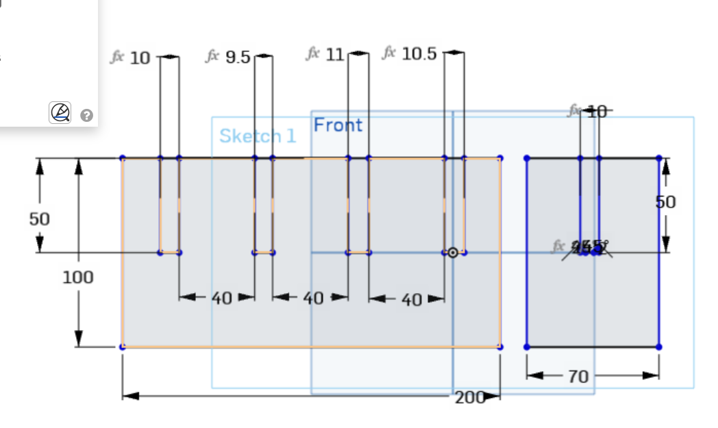
We designed a simple jig test on OnShape
And made a few parameters to test different sizes.

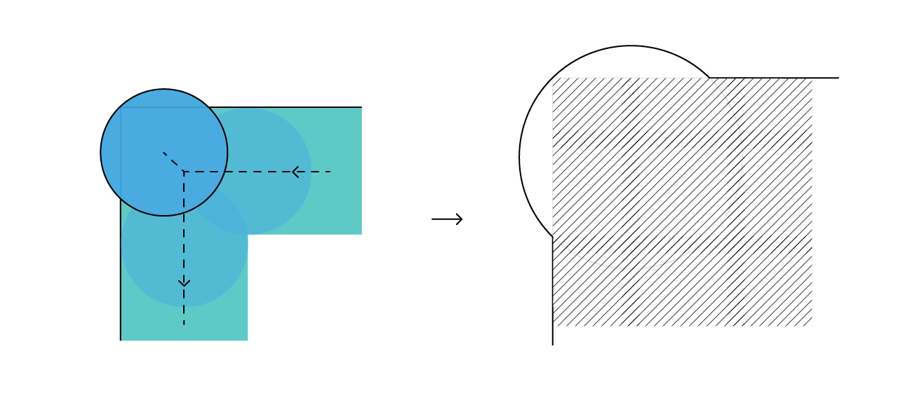
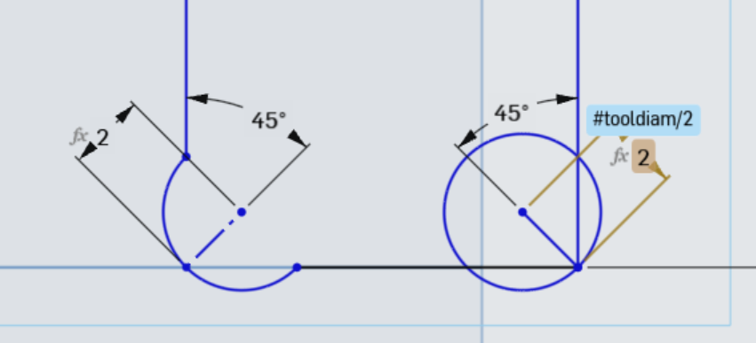
We also added a dogbone fillet to the inside corners of the jig’s slots. This is to compensate for the rounded shape of the end mill which has a 6 mm diameter, so sharp internal corners are impossible which would make fitting slots wrong.
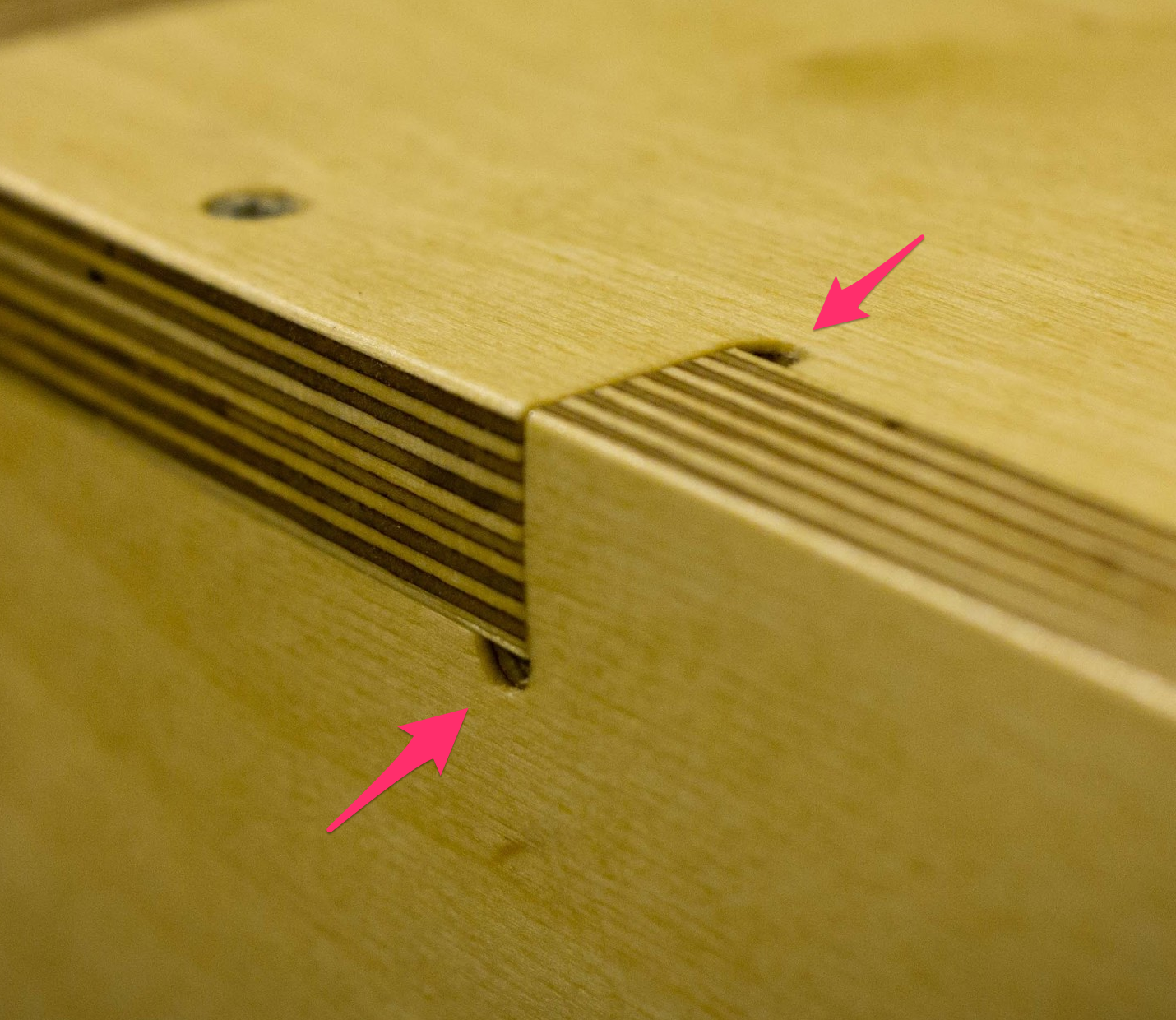
Here you can see why a dog bone is needed, to compensate for the rounded endmill
Test parameters:
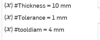
Drawing the dogbone size based on tool diameter
The test jig:
A video explaining them in detail.
https://www.youtube.com/watch?v=mHY1ia9GaFo
1. Runout Test
Runout refers to the wobble of the tool when rotating. Excessive runout can cause inaccurate cuts and rough edges.
We checked:
- Proper collet tightening
- Straightness of the end mill
- Stability of the spindle
[placeholder picture of tool alignment]
2. Feed Rate and Speed Test
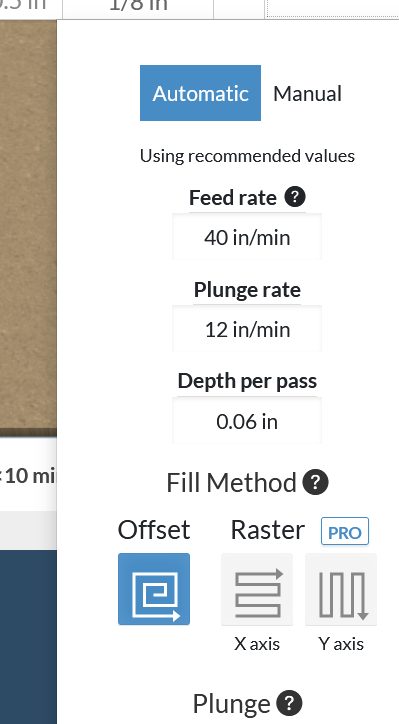
I am using easel from inventables as my CAM, I can design directly there or import G-code toolpath or an svg/dxf files.
I found this online calculator for cut settings, cncfeeds, easel will set the feed rate and other settings, but it’s good to double check before you start the job.
We tested different cutting parameters to determine the optimal settings.
Example parameters tested:
| Parameter | Value |
|---|---|
| Tool | 6 mm end mill |
| Spindle Speed | ~16000 RPM |
| Feed Rate | 1500–2500 mm/min |
| Depth per pass | 3–4 mm |
Before cutting we need to set the machine’s home, moving the axis from easel.
Observations:
- Lower feed rates produced smoother cuts.
- Larger depth per pass increased load on the tool.
3. Toolpath Test
We tested different toolpath operations:
- Pocket toolpath – removes material inside shapes
- Profile toolpath – cuts the outline of parts
- Tabs – small bridges left to keep parts attached to the board
Toolpaths were generated in Fusion 360 / Easel and previewed before machining to avoid collisions.
4. Alignment Test
To verify that the machine axes are perpendicular, we cut a square test piece to make sure the machine axes are correctly aligned.
We measured:
- Length of each side
- Diagonal distances
[placeholder picture]
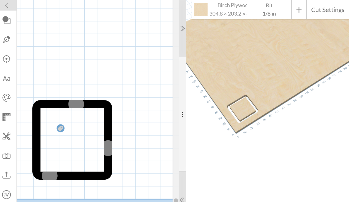
[picture the cut part]
🧪 Individual Assignment
Step 1 – Design
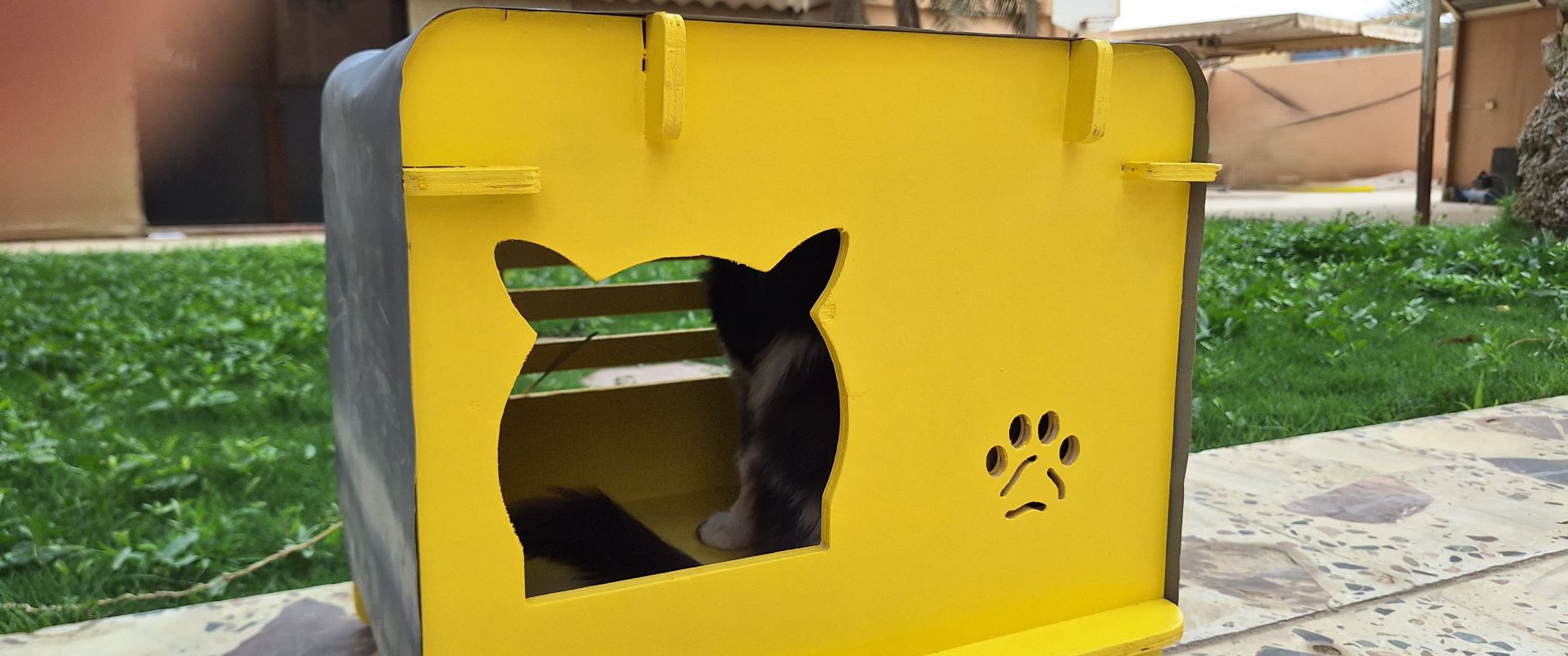
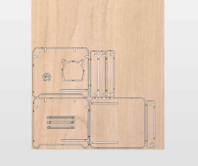
For my individual assignment, I had to cut something big, so I moved to a larger CNC Machine. I’m designing and making a house for my cat using a 11mm plywood. I made the design in OnShape, and exported it as dxf, in order to import into CNC’s CAM for fabrication, it was inspired by a product I saw online .
The sides will be covered by a fabric that the cat can use for scratching.
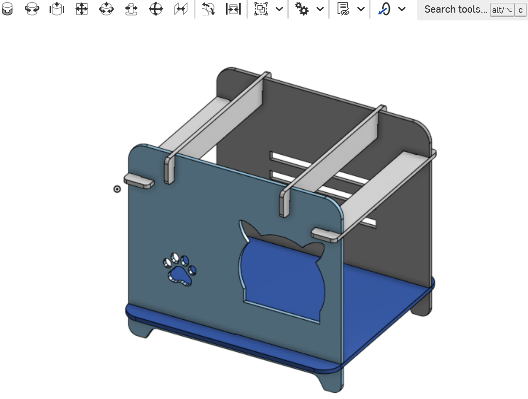
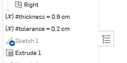
I made the material thickness and the tolerance as variable so I can change as I test the cutting.
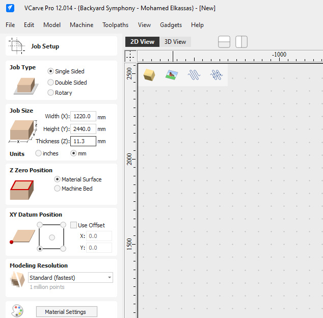
Step 2 – CAM Setup
Once the DXF files were ready, I imported them into the CAM software (I’m using VCarve) to prepare the toolpaths. Since I was working with 11mm plywood, I had to be precise with my settings to ensure a clean cut and a good fit for the joints. I entered the workpiece size, I’m using a full sheet here.
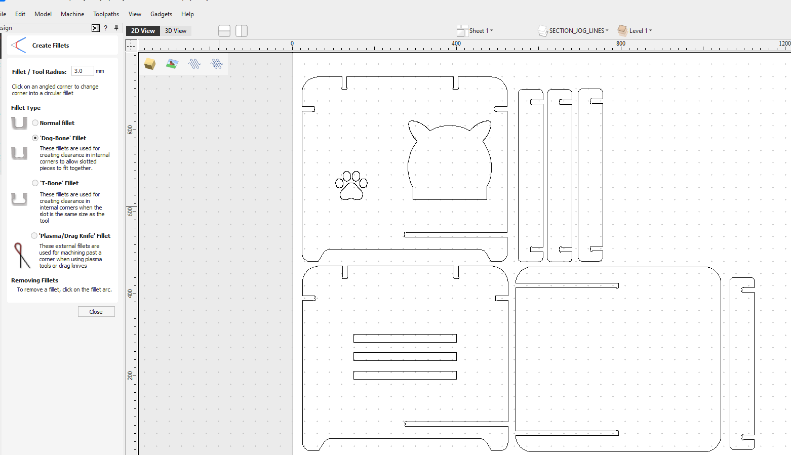
Because CNC bits are round, I added dogbone fillets automatically done by VCarve to all internal corners so the joints would fit flush:
Next, I entered the settings in CAM as follows for a 6mm 2 flutes down-cut endmill:
| Feed Rate | 5200 |
|---|---|
| Spindle Speed | 18000 |
| Plunge Rate | 300 |
| Depth Per Pass | 6mm |
I added 3D tabs to keep the pieces secure during the final pass, and then I executed the cut on two steps, first cutting the inner parts, then the outer, to make sure nothing goes wrong mid-cut:
Step 3 – Fabrication and Assembly
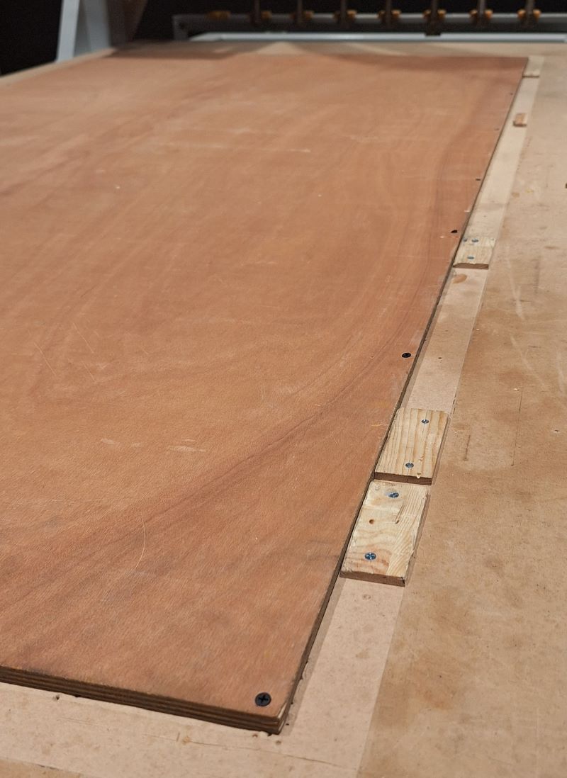
Before starting the machine, I secured the plywood sheet to the CNC bed using screws in the corners, ensuring they were well outside the cutting area.
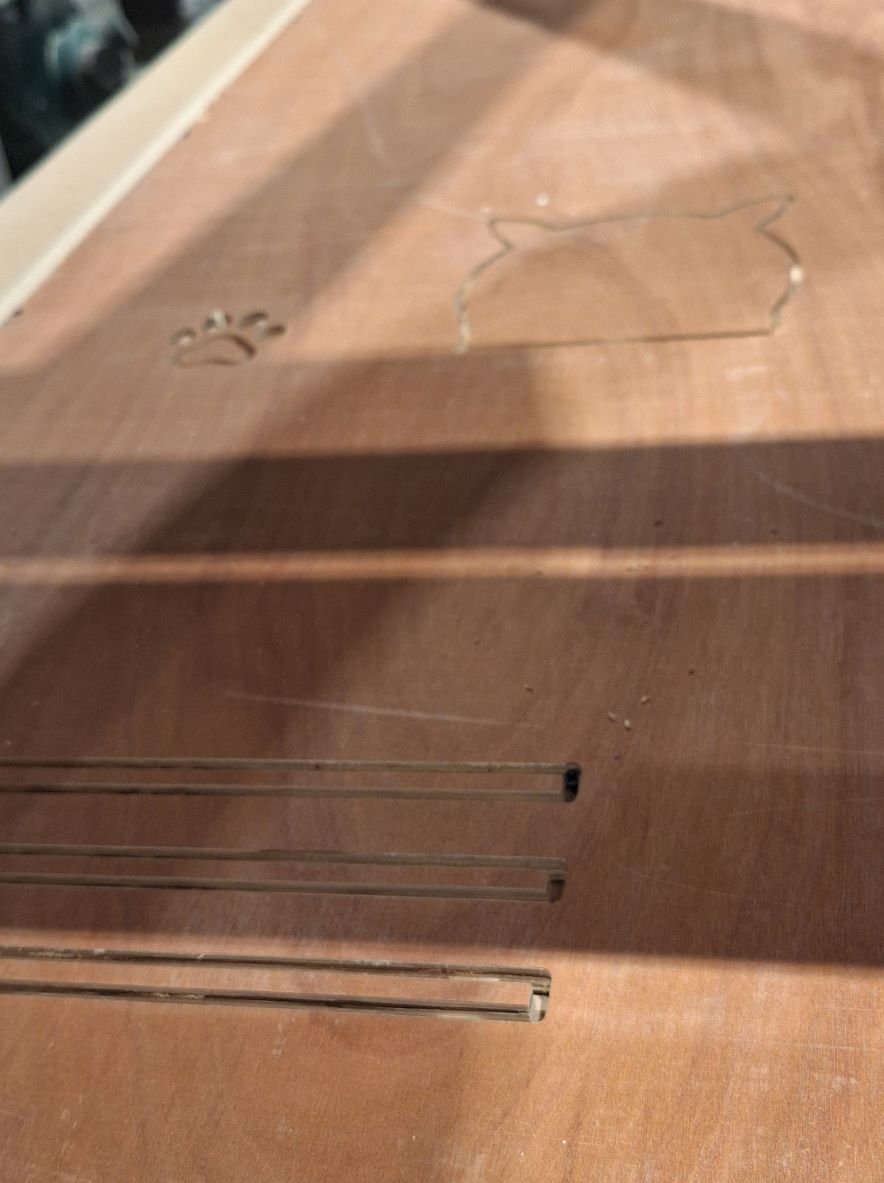
- The Cut: I performed a "dry run" first to check the cut was ok, by starting with inner parts. Once confirmed, I started the job. I stayed by the machine the entire time with the emergency stop at hand and wore ear and eye protection.
Followed by the outer parts:
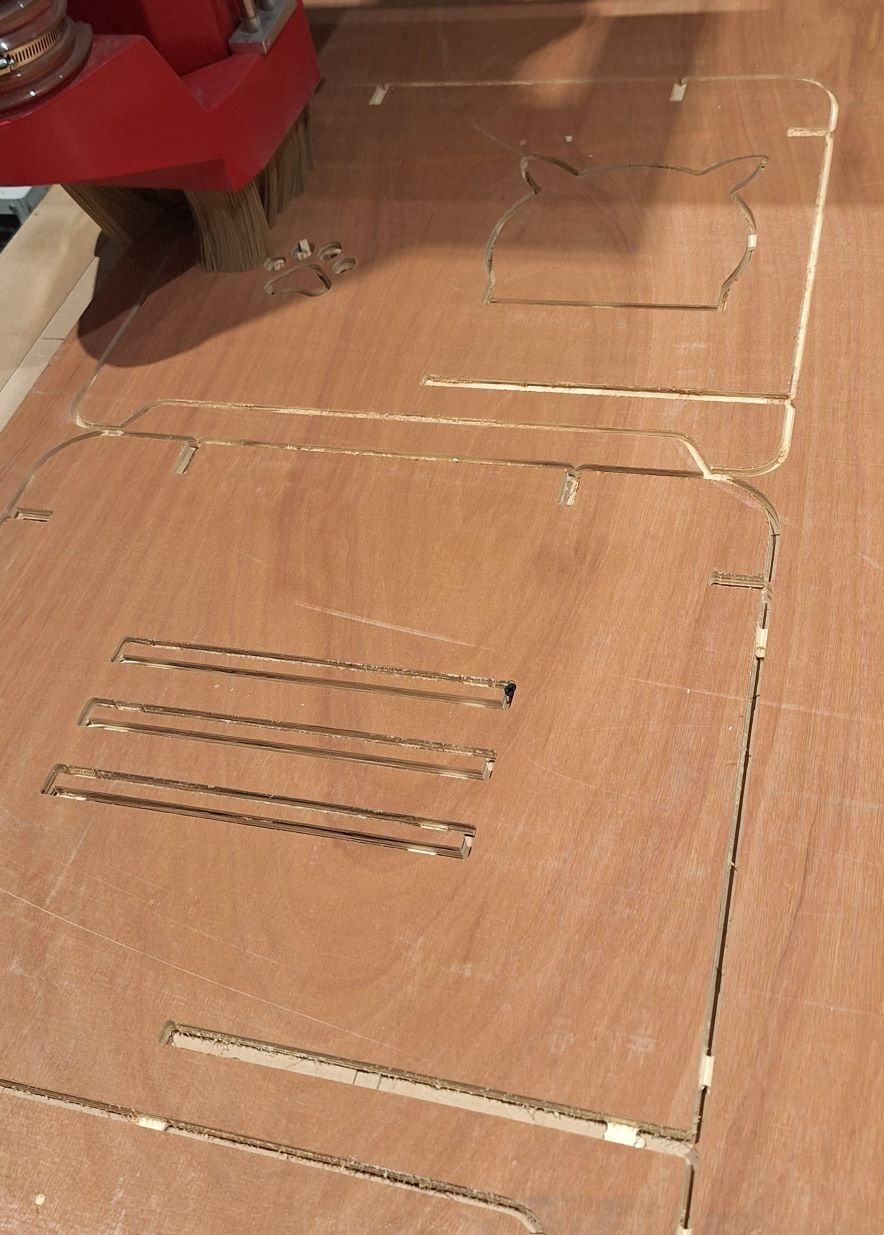
- Post-Processing: After the machine finished, I used a chisel to break the tabs. I sanded the edges to remove any burrs or rough spots.
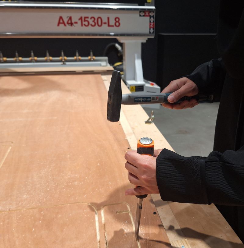
- Assembly: The pieces fit together using a press-fit technique. I used a rubber mallet to gently tap the joints into place.
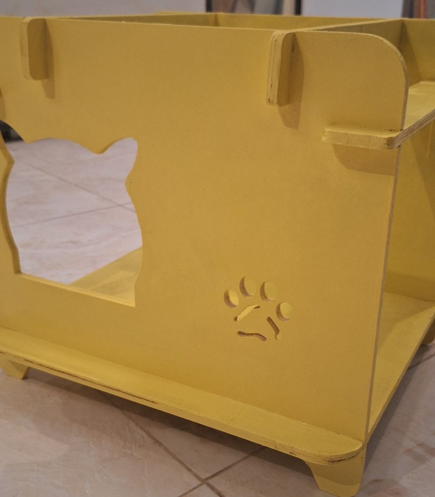
- Final Touches: To finish the house, I painted it with waterproof paint and wrapped the side panels in waterproof fabric. The structure is sturdy, and the 11mm thickness provides great stability.
⚠️ Problems & Solutions
- The joints for the cut parts are a bit too tight, I had to sand the slots to make them wider. I won’t repeat the cut but I am taking this into consideration and modifying the parametric design for an easier fit.
🧩 Files
📝 Reflection
- What you learned
- What you'd improve