Week 16 – System Integration
Fab Academy – Week 16
Date range: 6 - 12 May
Instructor: Neil
🧠 Learning Objectives
- Create a clear system integration plan for the final project.
- Document the integration plan using CAD and/or sketches.
- Implement appropriate packaging and enclosure methods.
- Design the final project to look and feel like a finished product.
- Document the system integration process and final assembly.
- Link the system integration documentation from the final project page.
📋 Assignments
Individual Assignment
Design and document the system integration for your final project.
🛠️ Tools & Materials
-
Gemini for proofreading and creating a template for the documentation
- Prompt: “I am on system integration week create a template for documenting my final project that meets the nueval evaluation criteria”
-
OnShape for documenting the design
- Materials (listed in the BoM below)
📁System Integration Strategy and Plan
We’ve come to the end. This week for me was a little bit challenging to document, as I felt I did a great job at planning and imagining how my final project should be integrated, but I didn’t know how I’m going to be able to reflect this with my documentation, but here we go.
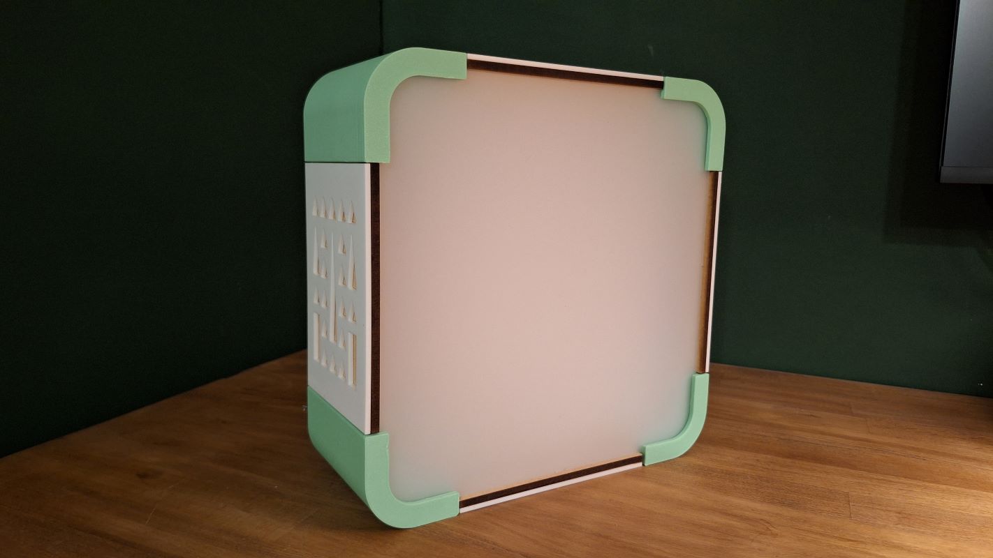
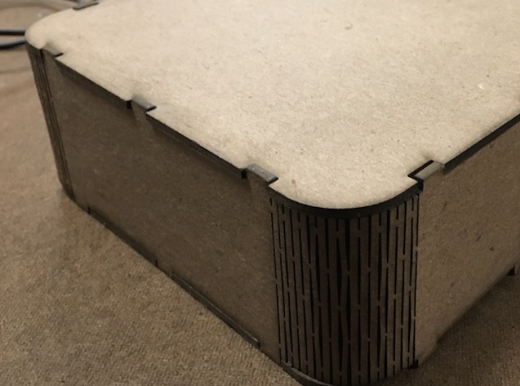
For my final project, the intent was to create a seamless, consumer-grade desktop device with zero visible raw wiring, flush external surfaces, a clean aesthetic, and modular panels that allow for easy disassembly and maintenance. I wanted the final product to resemble an old CRT TV—essentially a box about 25×25 cm. One challenge was the rounded corners: I didn’t want to use the common laser-cut corner method shown in the image below, because I see it often and I honestly don’t like it.
I wanted a design that would be more useful and complex, which means 3D printed, and yet it didn’t feel reasonable or challenging for me to 3D print the full box.
So I thought why not 3D print the corners and incorporate all features that are necessary for fitting and assembly into the corners and laser cut the rest. So here’s my final design:
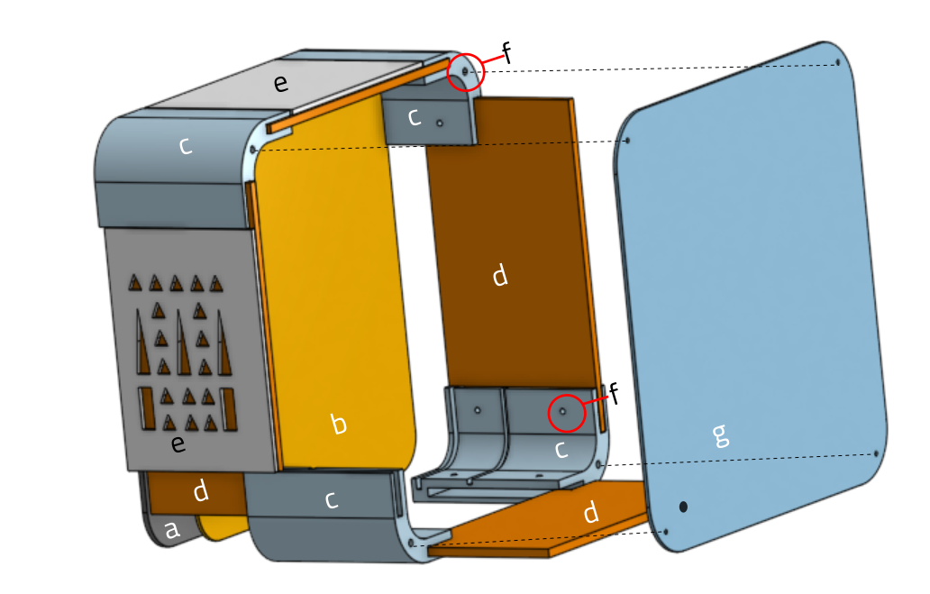
The Structural Module
| Item | Description | Fabrication | Quantity | Files |
|---|---|---|---|---|
| a | Front Panel: 2mm Translucent Acrylic Sheet used to cover LED strip and diffuse the light. | Laser Cut, 2mm acrylic sheet | 1 | frontPanel.dxf |
| b | Led Panel: White Acrylic Sheet. It’s where the Led strip will be fixed on in a grid with double sided tape. | Laser Cut, 3mm acrylic sheet | 1 | ledPanel.dxf |
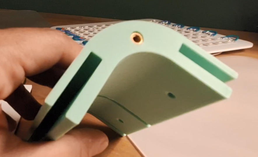
| c | Corners: It’s where the panels will slide into and has holes for fixing and securing everything together. | 3D Printed, PLA | 4 | lumaWell-Corner.stl |
| d | Side Panels: They slide into the 3D printed corners. 6mm MDF | Laser Cut, 6mm MDF | 4 | sidePanels.dxf |
| e | Decorative sides: They are just for decorative purposes, and they are glued to the side panels. | Laser Cut, 3mm acrylic sheet | 2 with motif and 2 plain | sideDecorative.dxf |
| f | Threaded Inserts and Screws. | Bought | 20 | NA |
| g | Back Panel: To cover the box and has an opening for power mount. | Laser Cut, 3mm acrylic sheet | 1 | backPanel.dxf |
The Electrical Module
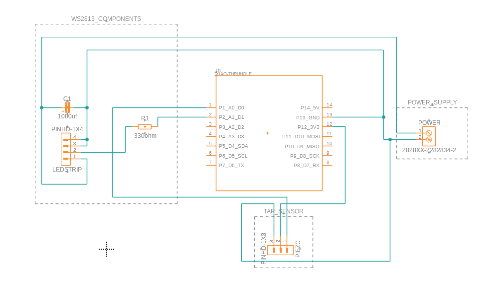
The main brain is an ESP32-S3 from Xiao, I am using 5v WS2813 strip of 121 leds, the device will be powered by an external power source, and to protect the electronics I’m using a power regulator that can take from 7V up to 36v, but always regulate the output voltage at 5V. I am also using a Piezo module which comes assembled with its tiny board. The PCB will hold the MCU and connect it to pin headers for the piezo, LED and power input.
Power Brick
    ↓
Buck Converter (set to 5.0V)
    ↓
+5V ---------------------> WS2813 +5V

GND ---------------------> WS2813 GND
  │
  └----------------------> ESP32 GND
  │
  └----------------------> Piezo - pin

XIAO ESP32S3 GPIO
    ↓
Piezo S pin

XIAO ESP32S3 3.3v
    ↓
Piezo + pin

XIAO ESP32S3 GPIO
    ↓
330Ω resistor
    ↓
WS2813 DIN

1000µF capacitor:
+ leg → +5V
- leg → GND
(across strip power input)
The PCB design:
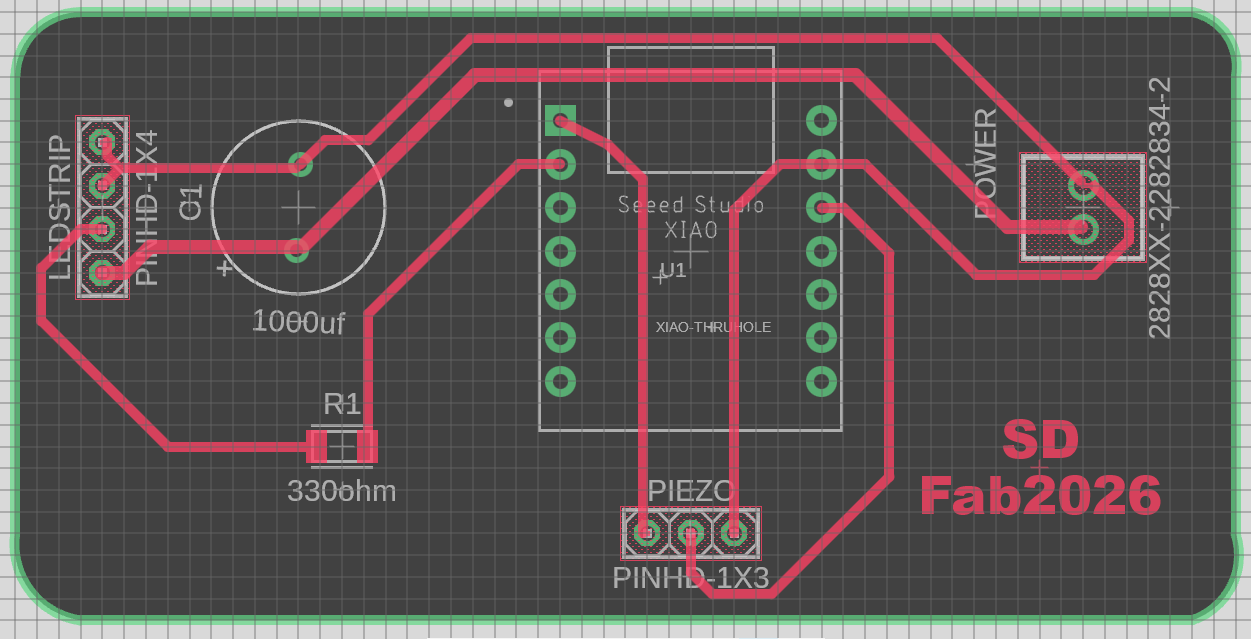
I added holes to the PCB so it can be attached to the bottom of enclosure.
Download the PCB design file here.
🧩 Fabrication and Assembly
Fabrication
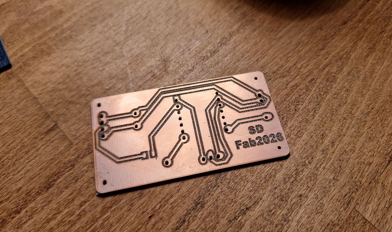
I tested a 50W Fiber laser machine for this final project and it turned out well, I had to do some power, speed, and frequency tweaking but at the end it was a success, more on the Electronic production week.
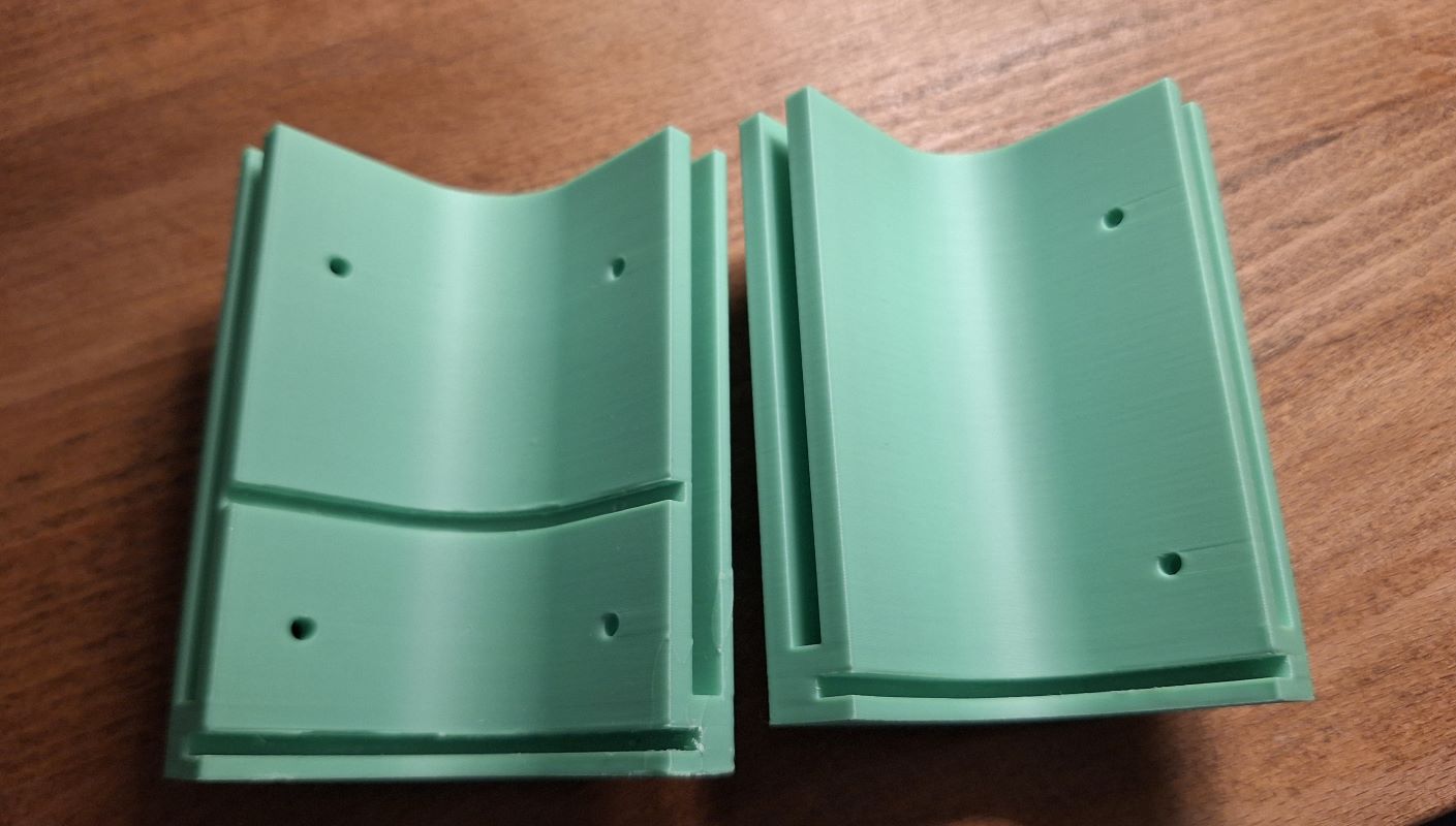
I 3D printed the first version of the corners during the 3D printing week, but later I realized I didn’t design a way to hold the LED panel, so I redesigned the corners and 3D printed them again. I used BambuLab printer with standard setting for PLA. Left, new, Right, old.
After 3D printing I inserted the threaded inserts into the hole to hold the screws later.
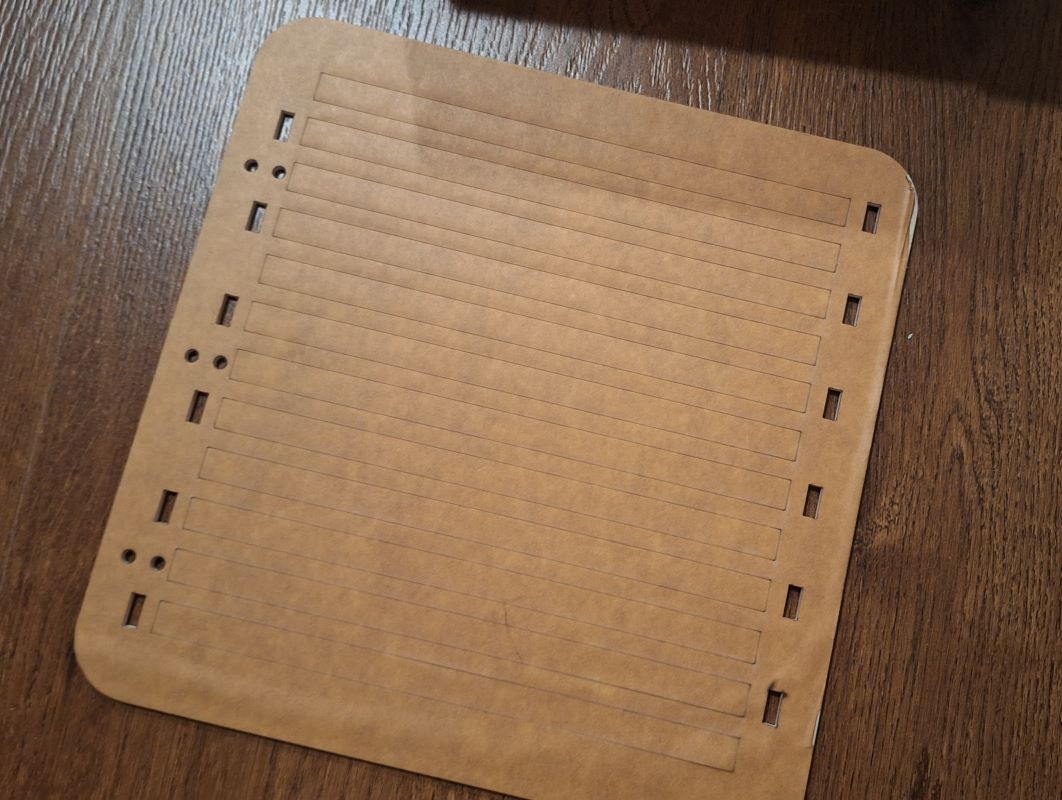
I laser cut the front and back panels, which were just squares with specific radius rounded corners, for the LED panel I added a scoring lines to help me align the LED strips, and openings to the sides so I can run the wires from to the back. Here’s an image before removing the backing sheet:
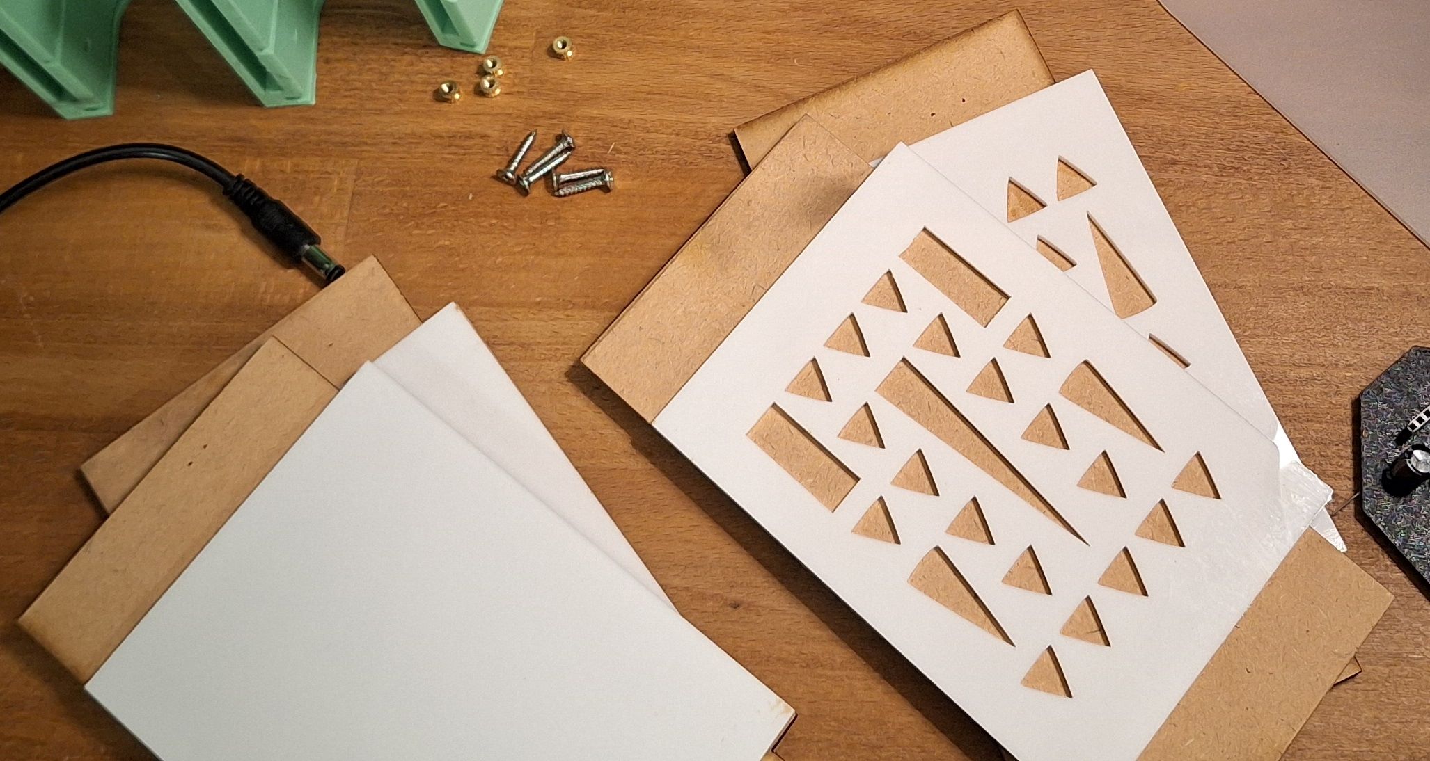
I laser cut the side panels with 5mm MDF and a decorative 3mm acrylic, I then glued them and pressed them until glue has dried.
Assembly
-
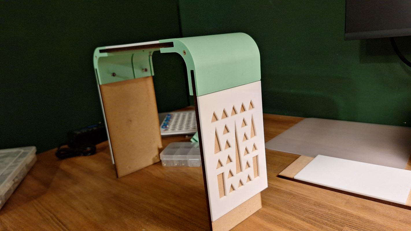
Step 1: The Frame & Sides: Sliding the side laser-cut panels into the 3D-printed corners to create the main box structure. But leaving the bottom corners open to slide the front and LED panels in.
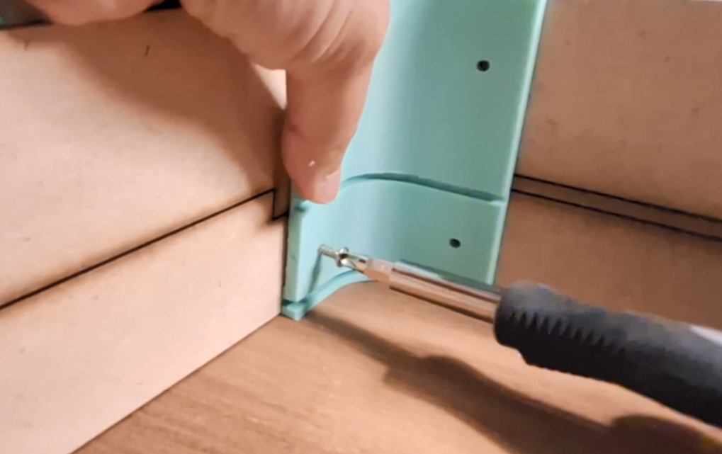
Then holding the sides with screws, I couldn’t find the proper size here 😃
-
Step 2: Front Panel Integration: Sliding the front panel into the forward-most slots of the 3D-printed corners.
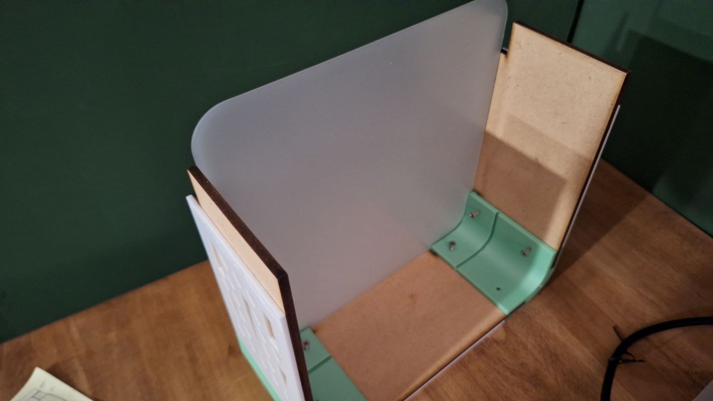
-
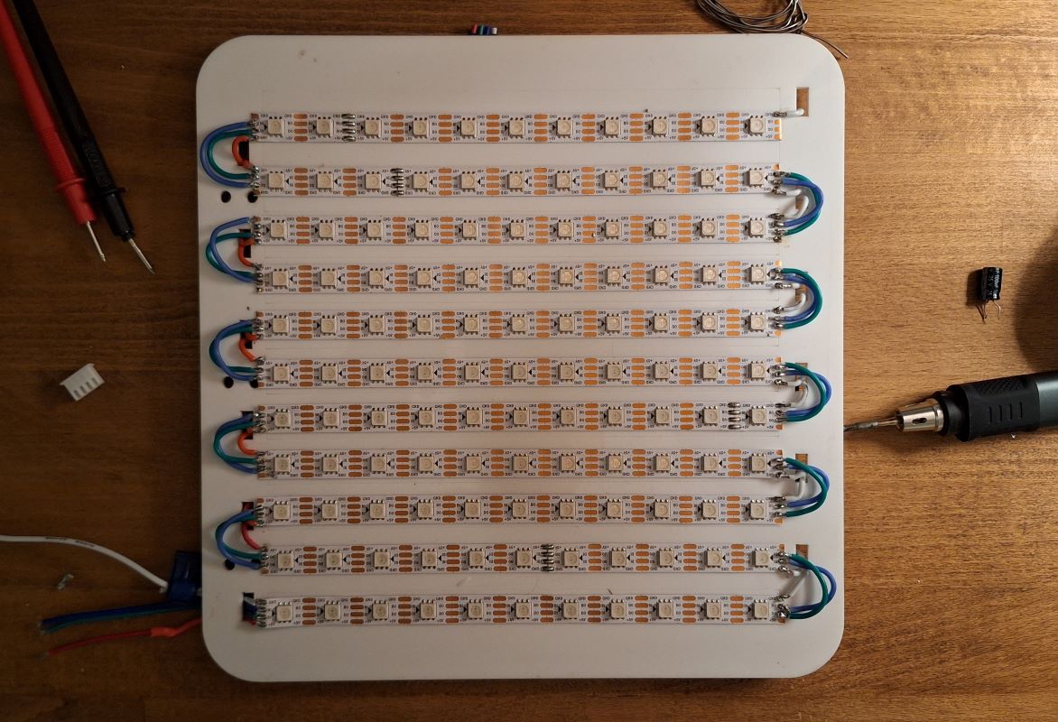
Step 3: Internal LED Layer assembly and integration: I laid out and soldered the grid of 11x11 LEDs in a serpentine layout, I started with the data and backup pins:
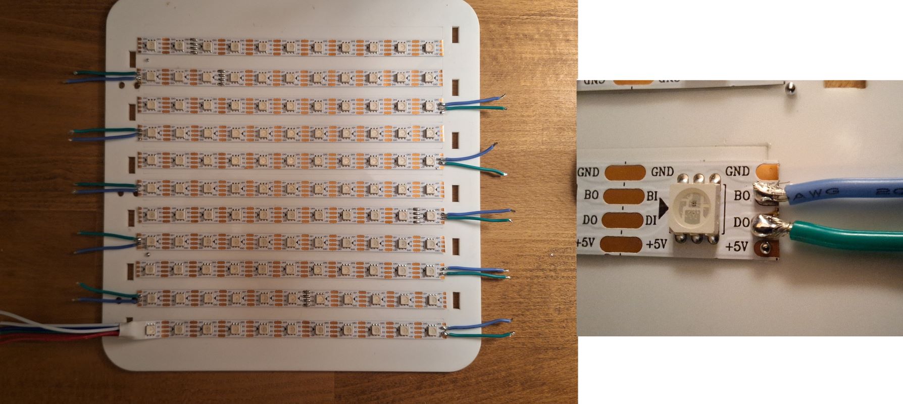
Then continued with power (left rail) and ground (right rail):
Final soldered LEDs from the back with heat shrink.
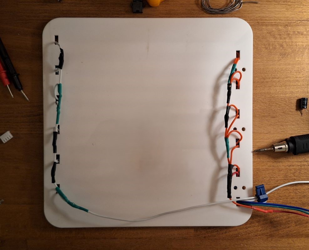
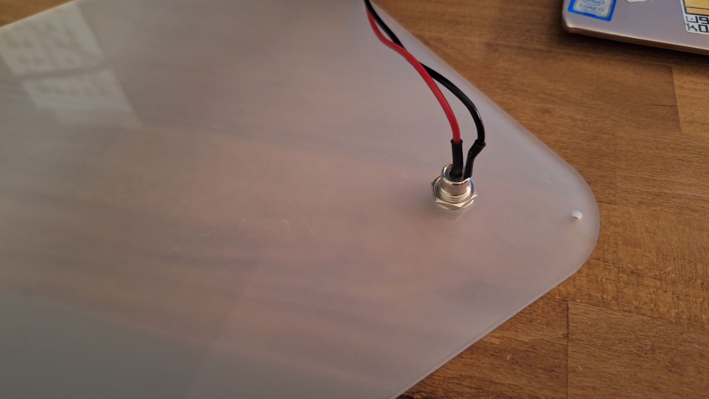
Then Sliding the panel holding the 121 WS2813 LED strip into the middle slots, right behind the front panel. I ran the wires through the holes to connect to the PCB later.
I know the protruding screws are annoying but they are doing the job well, I will change them once I find the right size.
-
Step 4: Electronics Mounting: Securing the custom milled PCB and the power converter module behind the LED panel inside the enclosure. (Explain how they are secured—double-sided tape, 3D printed clips, or standoffs?).
[Videos and images to be added later]
Attaching the Piezo module (I might need to design a holder for it)
-
Step 5: Closing the Bottom: Placing the bottom corners and the laser cut panel then securing with screws.
And then:
-
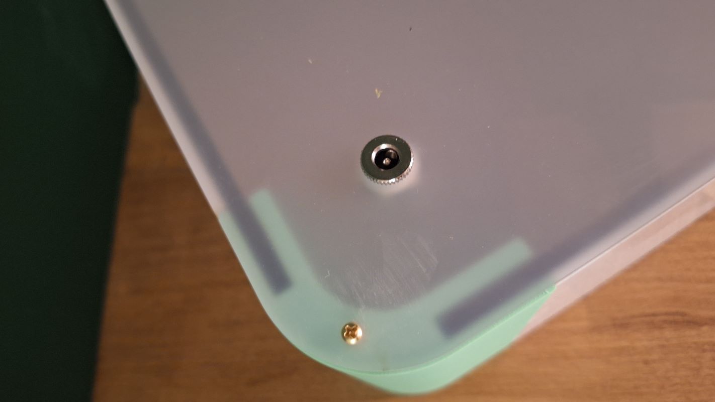
Step 6: Closing the Loop: Placing the back laser-cut panel on the back and securing it with machine screws into the 3D-printed corners' threaded inserts. After mounting the power mount.
Here's the screws inserted into the back panel and the threaded inserts
📊 Complete BoM
| Item | Description | Qty | Links | Notes |
|---|---|---|---|---|
| Enclosure | The one mentioned above in the Structural Module | 1 | ||
| MCU | Seeed Studio XIAO ESP32S3 | 1 | Amazon.sa | Compact, works well with WS2813 |
| LED Strip | WS2813 LED Strip 60LEDs/m | 1 | AliExpress | 121 5V addressable strip, arranged in a grid of 11x11 |
| Tap Sensor | Piezo Module | 1 | Amazon.sa | |
| Power Supply | 5V 3A regulated brick | 1 | Amazon.sa | |
| Power Regulator | 5v buck converter | 1 | Amazon.sa | DC-DC buck converter → regulated 5V |
| Data Resistor | 330 Ω resistor | 1 | Amazon.sa | Placed near strip DIN |
| Bulk Capacitor | 1000 µF, 10V electrolytic | 1 | Amazon.sa | Across strip +5V/GND near LED strip |
| Wire (Power) | 20 AWG silicone wire | as needed | Amazon.sa | For 5V/GND runs |
| Wire (Data) | 24 AWG | as needed | Amazon.sa | Short as possible |
| Connectors | JST PH 2.0mm Adapter Plug 3-pin and 4 pin | 2 | Amazon.sa | for LED and Peizo sensor connection |
| Connectors | Screw Terminal for Power 2-pin | 1 | Amazon.sa | for feeding power to the pcb |
| Connectors | DC mount | 1 | Amazon Bazaar | For external power supply |
| Fitting | Threaded inserts | 20 | Amazon Bazaar | Along with screws |
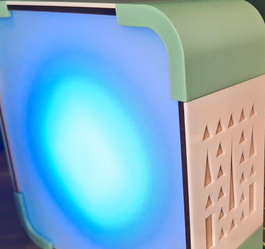
5. Testing & Results
Close up to show the fine finish and the diffused light.
6. Challenges & Learnings
- The Delay: Since the milling machine was not very accessible being in a different lab, it took the most time to produce, but I continued designing and fabricating the enclosure ahead of time so it allowed me to test the mechanical integration before dropping the electronics in.
- Side Panels Fabrication: from the get-go I designed my project to be parametric, and this helped me alot since I didn’t know what material was available to use, and I initially planned to CNC cut the side panels each as one piece, but I later couldn’t find the right material so I drifted to the double layered sides.
- Screw sizes are my worst nightmare, there aren’t much options in the lab and most of the threaded inserts are not the right size. Plus I need to learn more about screws, and how to design and fabricate around them!!