Week 12&13 – Machine Design
Fab Academy – Week 12-13
Date range: 8 - 21 April
Instructor: Neil
🧠 Learning Objectives
- Work and communicate effectively as a team
- Design, plan and build a machine
- Analyse and solve technical problems
- Recognise opportunities for improvements in the design
📋 Assignments
Group Assignment
- Actuate and automate your machine
- Document the group project and your individual contribution
- Prepare a demonstration of your machines for the next class
🧪 Individual Documentation & Contributions
Role Overview: Except for the specific mechanical design of the clay nozzle assembly, I engineered and executed the end-to-end development of this machine. This included mechanical teardown, upgrading to an Open Source Ecology (OSE) universal axis design, transitioning from belt to lead screw extrusion mechanics, custom RAMPS 1.4 electronics wiring, Marlin firmware hacking, and ultimately designing the structural pivot to a pen plotter when the clay physics failed.
Mechanical Fabrication & Machine Assembly
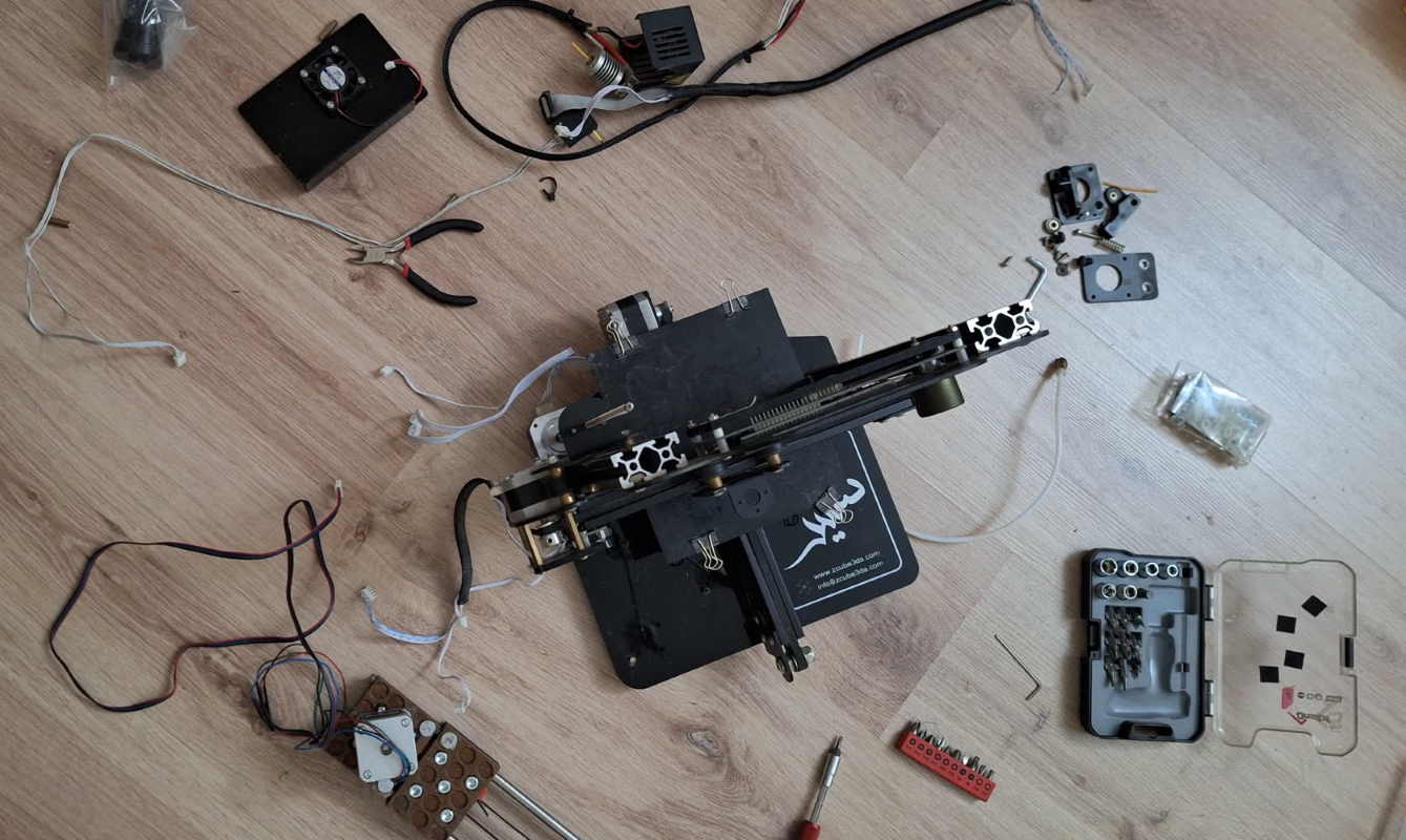
Teardown and OSE Axis Integration
I stripped the legacy 3D printer down to its bare frame, cleaned the linear rods, and integrated the Open Source Ecology (OSE) Universal Axis. This modular axis design was meant to give us a highly robust linear carriage capable of handling the weight of a raw clay payload.
The Extruder Evolution: From Belt to Lead Screw
- The Belt Mechanism (Failed): Initially, a NEMA 17 motor used a GT2 timing belt to pull the syringe plunger downward. Under the sheer viscosity of the clay, the teeth on the belt skipped across the motor pulley, resulting in zero extrusion.
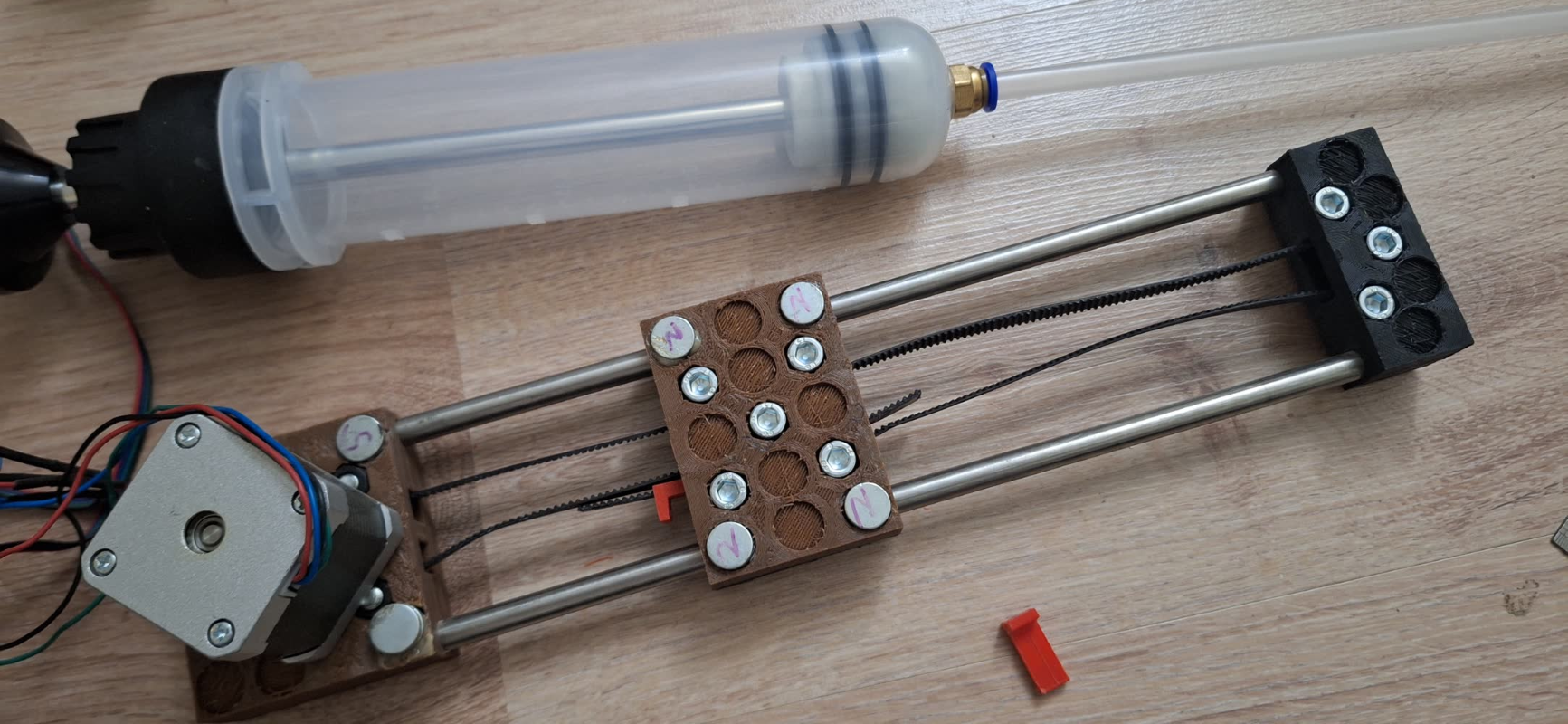
- The Lead Screw Mechanism (Custom Designed): I explicitly designed and 3D-printed custom mechanical housing parts to adapt the extruder to a lead screw drive. This converted the radial torque of the NEMA 17 directly into linear force. However, during testing, the lead screw pitch wasn't optimal for the fine paste application, causing the plunger to move at an incorrect linear pace relative to our X/Y coordinates.
Wiring Architecture & PCB Integration
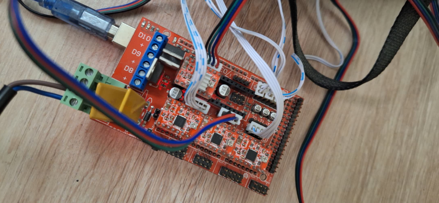
- Stepper Drivers: I plugged A4988 stepper drivers into the RAMPS shield, using jumpers underneath the drivers to set 1/16 microstepping for the X, Y, Z, and Extruder ($E_0$) channels.
- Current Limiting ($V_{ref}$ Calibration): Because pushing clay demanded maximum torque, I manually tuned the potentiometer on the A4988 drivers using a multimeter. I brought the $V_{ref}$ up to approximately $0.65\text{V}$ for the axes and pushed the extruder driver to its safe limit to prevent the motor from stalling under pressure.
+-------------------------------------------------------+
|                 Arduino Mega 2560                     |
+-------------------------------------------------------+
                           |
            [RAMPS 1.4 Shield Integration]
                           |
    +----------------------+----------------------+----------------------+
    |                      |                      |                      |
[X-Axis A4988]       [Y-Axis A4988]        [E0 Extruder A4988]     [Z-Axis A4988]
    |                      |                      |                      |
(NEMA 17 Motor)      (NEMA 17 Motor)       (Lead Screw Motor)    (Lead Screw Motor)
Marlin Firmware Configuration & Snippets
To handle the custom mechanics and the eventual shift to a plotter, I heavily modified the Configuration.h file in Marlin.
Key Firmware Changes & Code Snippets
1. Mechanical Steps-Per-Unit Calibration
Because our lead screw wasn't the standard pitch typically used in 3D printers, the default steps-per-mm values caused highly distorted movements. I had to mathematically calculate and adjust the steps for the Extruder ($E$) axis.
C++
// Base Marlin configuration for axis steps per mm
// Format: { X, Y, Z, E0 }
// Calculated based on 200 steps/rev, 1/16 microstepping, and our specific lead screw pitch
#define DEFAULT_AXIS_STEPS_PER_UNIT   { 80.00, 80.00, 400.00, 952.38 }
2. Disabling Extruder Thermal Protection (Cold Extrusion Prevention)
Marlin has a safety feature built-in that prevents the extruder motor from turning unless the hotend is heated to at least $170^\circ\text{C}$. Since clay printing is a cold process, the motor refused to move. I had to explicitly disable this check in the code:
C++
// Prevent Marlin from blocking extruder movement when cold
#define PREVENT_COLD_EXTRUSION
#define DEFAULT_MIN_EXTRUDE_TEMP 15  // Lowered from 170 to allow ambient room temperature clay extrusion
3. Feedrate and Acceleration Tuning
To prevent the stepper motors from skipping when transitioning from the light pen plotter load to the heavy clay load, I dropped the maximum acceleration values to ensure high torque retention:
C++
#define DEFAULT_MAX_FEEDRATE          { 300, 300, 5, 25 }
#define DEFAULT_MAX_ACCELERATION      { 1000, 1000, 50, 100 }
Why the Clay Printer Failed:
- Belt Skipping on OSE Axis: The resistance of packed clay inside the chamber caused the initial OSE belt-driven assembly to skip teeth immediately, losing all spatial tracking.
- Lead Screw Mismatch: Shifting to my custom lead screw design solved the mechanical skipping, but because the lead screw was an incorrect type/pitch, the linear travel was completely out of sync with the firmware’s calculation, leading to inconsistent material flow (pulsing or under-extruding).
- Non-Newtonian Fluid Dynamics: Without a perfectly calibrated industrial pressure plunger, structural flex in our 3D-printed parts caused the clay to settle, pack, and cause flash-clogs.
6. Software Workflow & G-Code Pipeline
With the machine running Marlin, the pipeline seamlessly processes standard vector formatting into physical paths.
[Inkscape / Vector Design] ➔ [G-code Export (Nozzle/Pen height as Z)] ➔ [Pronterface] ➔ [RAMPS 1.4 / Marlin]
- Design Creation: Paths are generated as standard vector layers in Inkscape.
- G-Code Generation: The paths are converted into 3D printer friendly G-code. Since Marlin controls the Z-axis natively, "Pen Up" is handled by executing a quick Z travel command (e.g.,
G1 Z5), and "Pen Down" is handled by bringing it to tracing depth (e.g.,G1 Z0). - Machine Execution: The G-code file is loaded into Pronterface, which streams the coordinates directly to the Arduino Mega over USB at a baud rate of
115200.
7. Testing, Debugging Narrative, & Functional Proof
Debugging Log (Chronological Narrative)
- Issue 1: Extruder Motor Dead on Arrival
- Symptom: When sending manual extrude commands via Pronterface, the motor wouldn't budget or click.
- Fix: Discovered Marlin's
PREVENT_COLD_EXTRUSIONsafety block. ModifiedConfiguration.hto lowerDEFAULT_MIN_EXTRUDE_TEMPto15, allowing the room-temperature paste extruder motor to fire.
- Issue 2: Mechanical Jitter and Calibration Errors on the Lead Screw
- Symptom: The custom lead screw extruder moved, but the distance travelled didn't match the commanded millimeters, causing the clay to either stall out or over-pressurize.
- Fix: I mathematically recalculated the steps/mm value using the pitch of the mismatched lead screw and re-flashed Marlin via the Arduino IDE until the physical travel matched our digital inputs.
- Issue 3: Extruder Driver Overheating
- Symptom: The extruder stepper motor would run for 2 minutes and then completely cut power.
- Fix: The A4988 driver was pulling too many amps trying to force the lead screw through dense clay, hitting thermal shutdown. I backed down the $V_{ref}$ potentiometer slightly and mounted an active cooling fan directly over the RAMPS shield.
Functional Proof
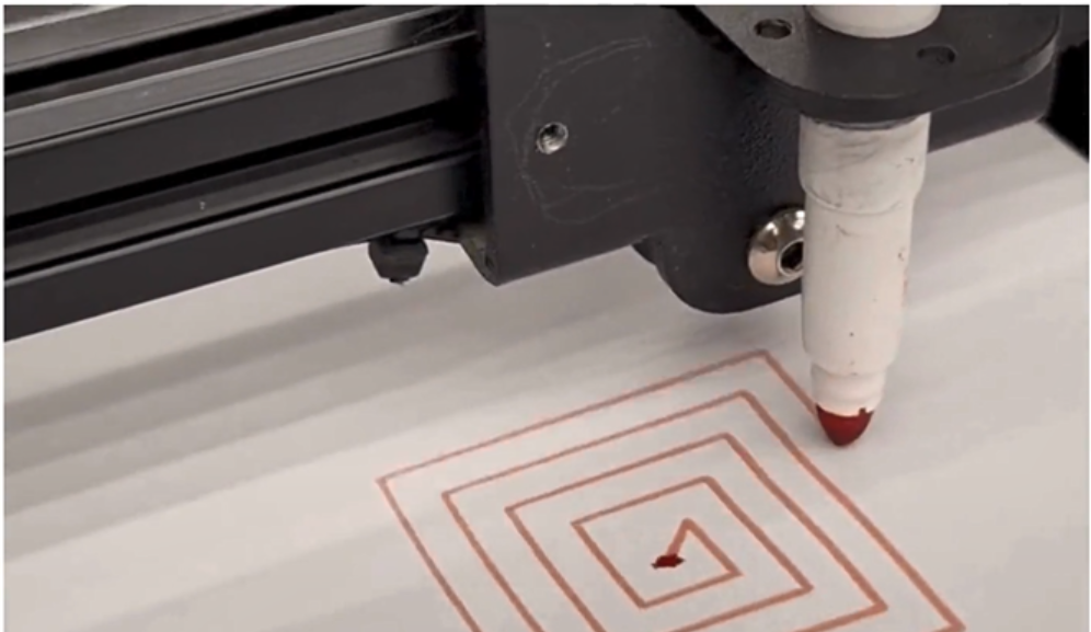
Following the pivot to the pen plotter setup, the machine successfully executes vector geometries.
🧩 Files
- Extruder Design files
- Clay Printer Firmware configuration
- Clay Printer Firmware advanced configuration
📝 Reflection
While modifying this machine ultimately led to a functional pen plotter, I view the clay printing phase as a profound, constructive failure. Spending nine intensive days troubleshooting the Open Source Ecology universal axis, watching timing belts skip under load, and designing custom mechanical housings only to have a mismatched lead screw pitch throw off the feedrate was an intense lesson in applied fluid dynamics and torque mechanics.
Choosing to pivot to a pen plotter was an executive project management decision to guarantee a working delivery for this cycle, but the story of my clay printer doesn't end here. The physical constraints of handling a non-Newtonian material like clay simply exposed the limitations of my repurposed hardware frame, not the concept itself. I have already begun diagnosing the exact mechanical deficits of this iteration, and I fully intend to return to this design armed with a corrected lead screw assembly, a rigid structural chassis that eliminates flex, and a highly tuned Marlin environment, until I successfully master paste extrusion printing.