Week 9 – Input Devices
Fab Academy – Week 9
Date range: 18 - 24 Mar
Instructor: Neil Gershenfeld
🧠 Learning Objectives
- Demonstrate workflows used in sensing something with input device(s) and MCU board
📋 Assignments
Individual Assignment
- Measure something: add a sensor to a microcontroller board that you have designed and read it.
Group Assignment
- Probe an input device(s)'s analog levels and digital signals (As a minimum, you should demonstrate the use of a multimeter and an oscilloscope.)
🛠️ Tools & Materials
- Software (Fusion360 and EasyEDA for electronics)
- Machines (Silhouette Cameo)
- Materials (Piezo sensor, resistors, led, Xiao SAMD21)
👥 Group Assignment
This week’s group task was to probe an input device's analog levels and digital signals using an oscilloscope and a multimeter. We used a Keysight EDUX1002A oscilloscope, a digital multimeter, and a DC power supply to see how different sensors react or read and write.
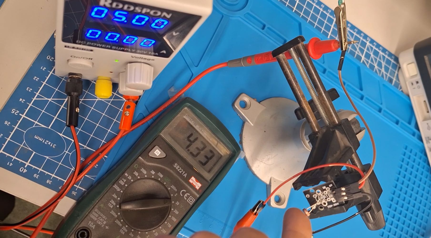
The Setup To start, we set the power supply to 5V, connected the ground of power supply to the ground of the sensor and the power to power the sensor, lastly the data pin will be connected to the multimeter or the oscilloscope.
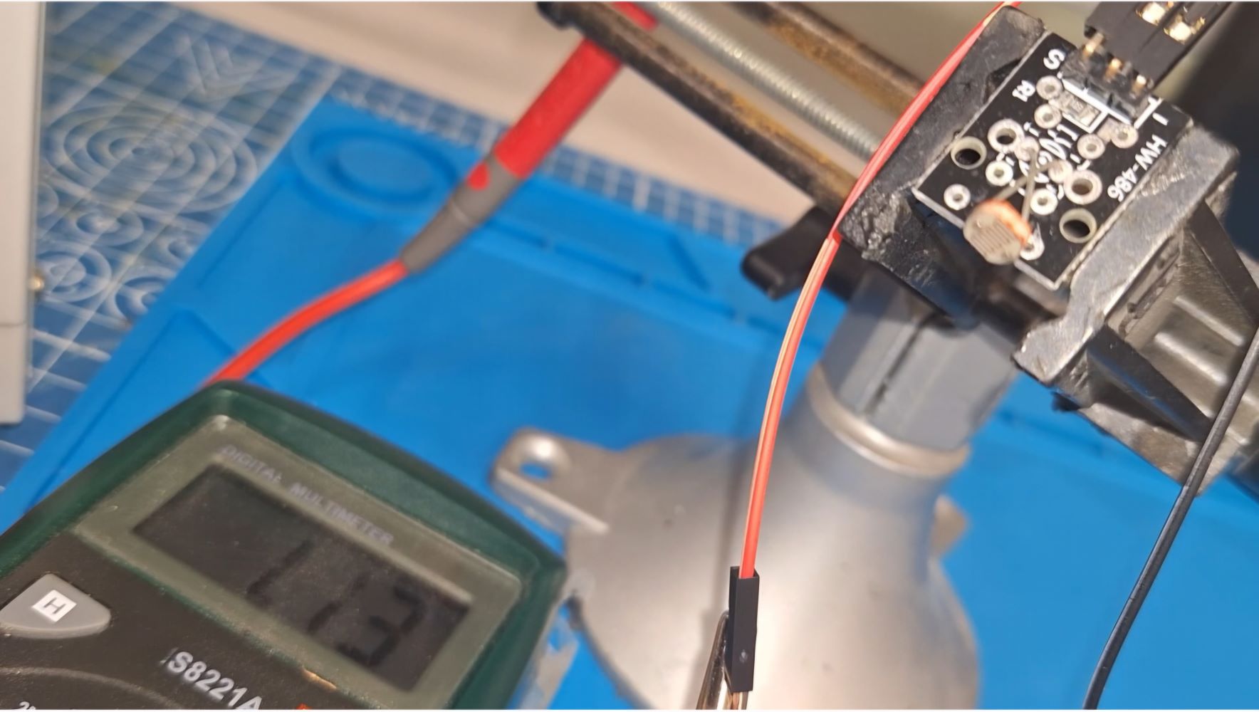
Step 1: Measuring Analog Levels with a Multimeter We started with a 3-pin photoresistor module to observe how voltage changes based on light intensity. Using the multimeter set to DC Voltage, we probed the AO (Analog Out) pin and recorded the following:
- Normal Light: ~2.88V
- Total Darkness (Covered): ~4.3V
- Shining a Light: ~1.13V
Covering the sensor, darkness:
Bright light:
Step 2: Characterizing the Analog Wave on the Oscilloscope To see the how this voltage changing, we moved the oscilloscope probe to the AO pin. we adjusted the scale to 1V per division. This allowed us to see a smooth wave as I waved my hand over the sensor, proving that analog signals provide a continuous range of values.
[IMAGE PLACEHOLDER: Photo of the Oscilloscope showing the analog wave]
Step 3: Observing Digital Pulses with the Oscilloscope We then switched to a 3-pin push button module to see a digital signal, using the same connection as before. Unlike the photoresistor, the line on the screen didn't "slide" it stayed at 0V and snapped instantly to 5V when we pressed the button.
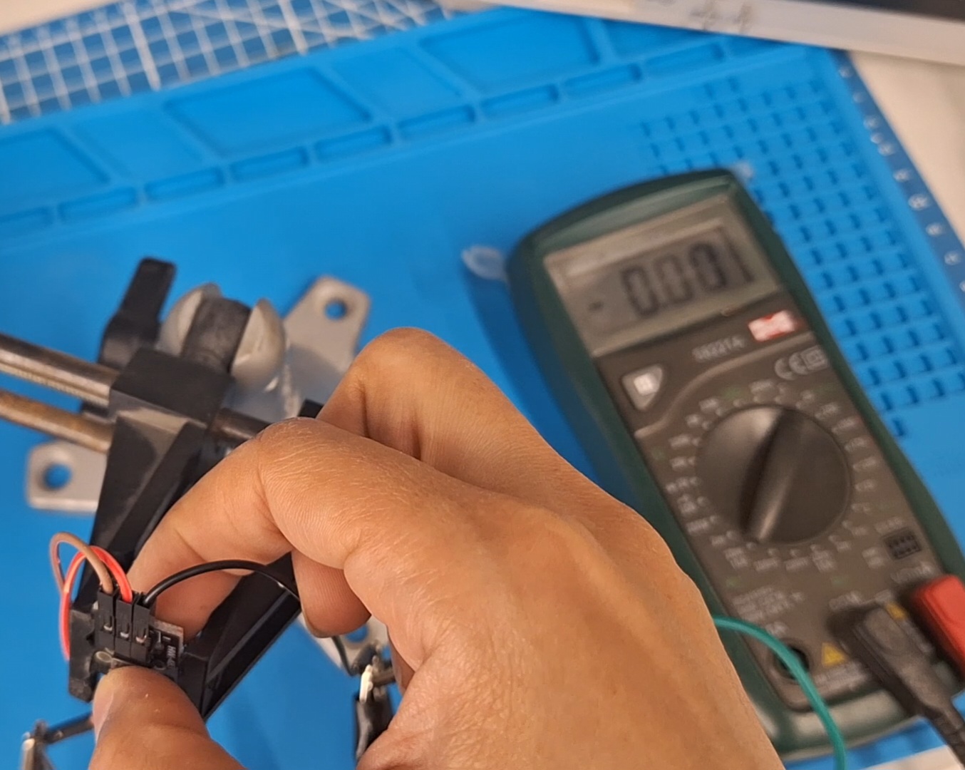
Step 4: Verifying Digital Logic with the Multimeter Finally, we checked the button with the multimeter to confirm the logic levels. I held the button down to see a steady 5.0V (Logic HIGH) and released it to see 0.0V (Logic LOW). This confirmed that the digital signal is binary, with no intermediate values like the photoresistor.
Unpressed:
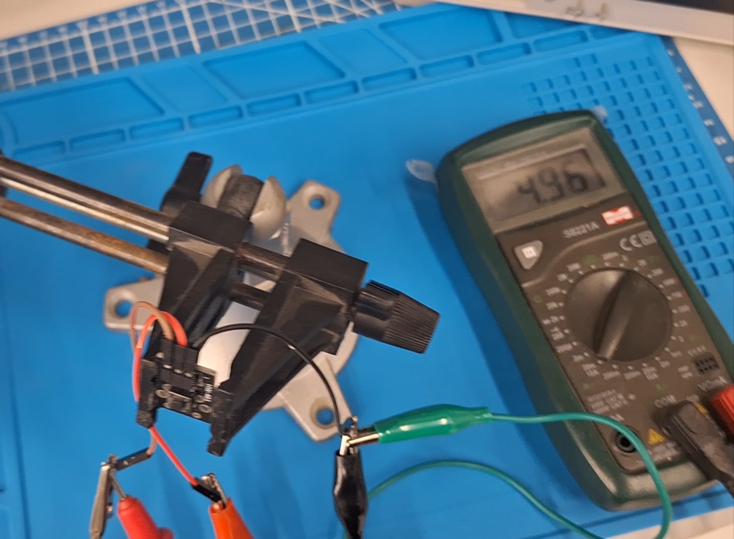
Pressed:
Conclusion By testing these two devices side-by-side, the difference between analog and digital became very clear. The Analog signal is a continuous wave representing a range, while the Digital signal is a binary state (ON/OFF) with a sharp threshold.
🧪 Process & Workflow
For this week’s assignment, I will be building towards my final project, so I will test input from a piezo sensor module and output to an led which I will replace next week for my output assignment.
So, basically I want my device to detect a single or double tap and change mode accordingly. In this test, one tap will make the led light up for 1 second and double tap will make led blink.
I will use for microcontroller the Seeed Xiao SAMD21.
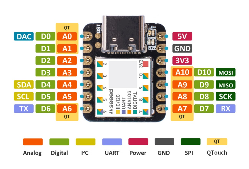
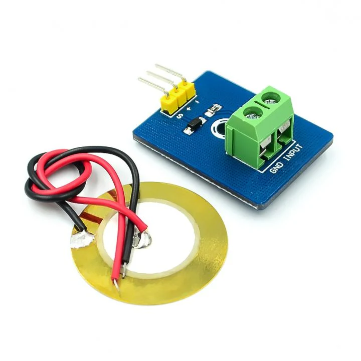
I will use the piezo sensor module, since I couldn’t find the right resistors and the module comes ready with its resistors.
Step 1 – The Circuit
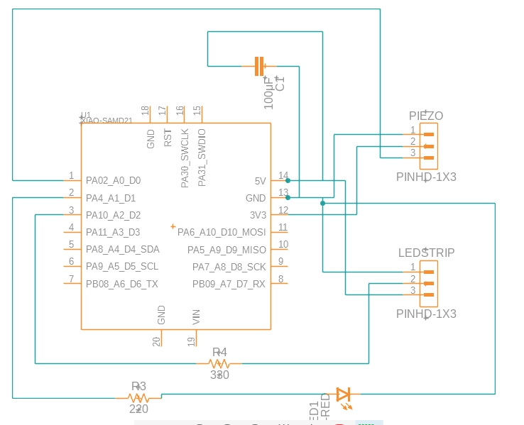
I built the circuit with two workflows.
The first one was using Fusion360, it was pretty similar to KiCAD, I placed my components and then connected them, I added pins for my next week’s assignments for connecting the WS2812b LED strip, it requires a capacitor and a 330ohm resistor as well:
Then I moved to routing and drawing the board’s outline:
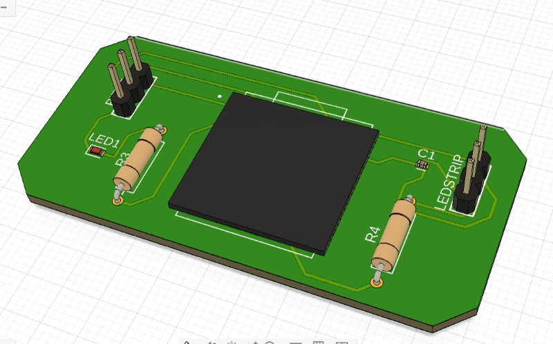
Final 3D model for the PCB to be milled:
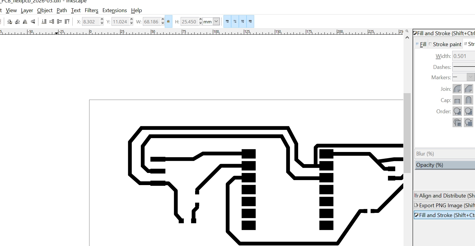
I didn’t have time to mill the board yet, so I decided to test another PCB production workflow, which was using a vinyl cutter. I recreated the circuit on EasyEDA (just to test different software) and exported the routes as pdf, which I then modified a bit on inkscape, I increased the thickness of some of the routes:
I used a Silhouette Cameo vinyl cutter to cut a copper tape. I applied the copper tape directly on a plastic sheet, to avoid having to transfer the intricate lines, I then fed the sheet directly to the vinyl cutter without the mat, I changed the size of blade to 2, and in the software the Silhouette Studio, I chose washi paper as the cutting material and lowered the speed (12) and force (2).
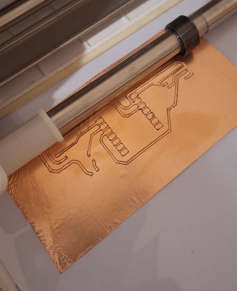
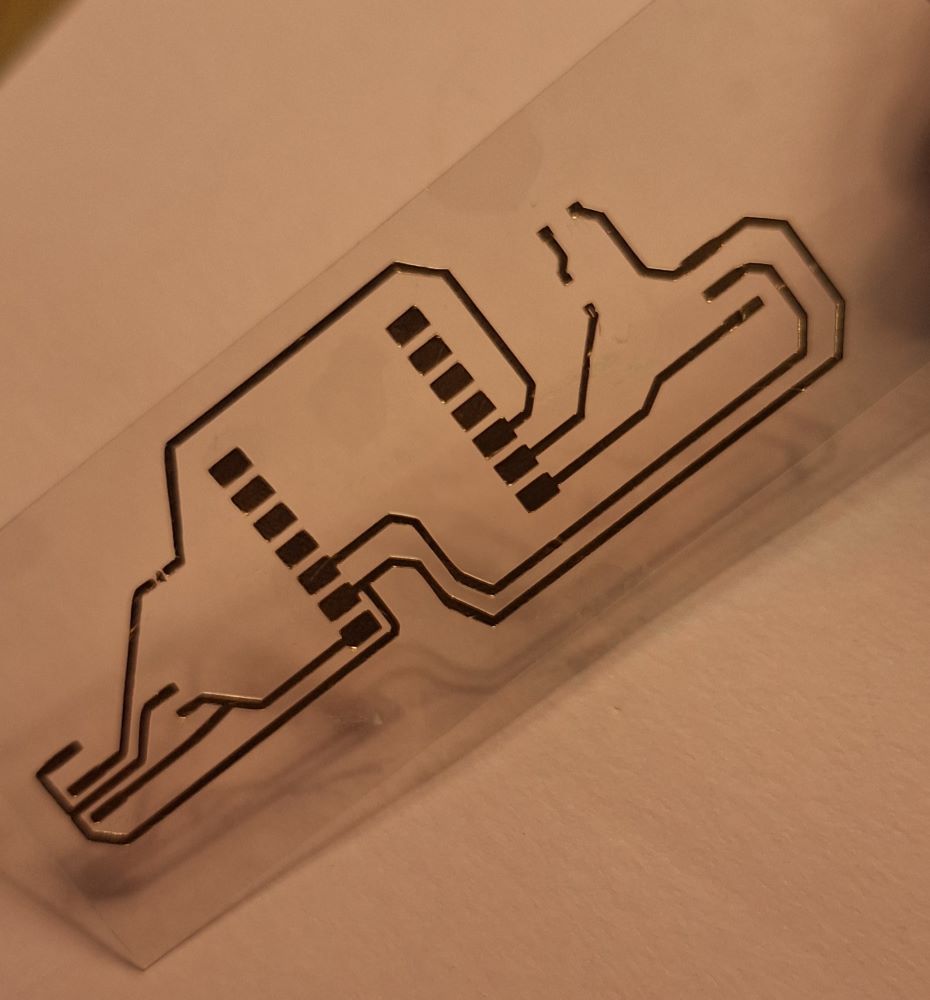
After it cut the cooper tape I weeded the extra unwanted pieces and ended up with a circuit on flexible plastic sheet.
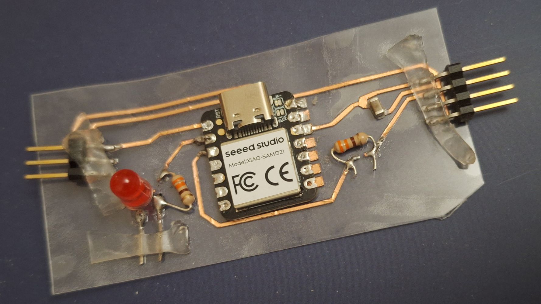
Step 2 – Assembly & Soldering Process
Because the vinyl circuit substrate is made of flexible thin plastic, traditional high-heat soldering iron tips will melt the base sheet immediately. To safely mount the components, I used a precision low-temperature soldering technique:
- Component BOM Checklist:
- 1x Seeed Studio XIAO SAMD21
- 1x Piezo Sensor Element
- 1x 1M Ohm Resistor (for pull-down signal stabilization)
- 1x Surface Mount LED (for basic output testing)
-
1x 330 Ohm Resistor (current limiting for test LED)
-
Soldering Workflow: I set my adjustable soldering iron to a conservative 280°C. I applied a small dab of solder flux directly to the copper tape pads, tinned the copper tracks quickly to avoid overheating the adhesive, and carefully placed and jointed each SMD component.
- Continuity Verification Test: Before plugging the board into power, I used a digital multimeter set to Continuity Mode (BEEP). I touched the probes to the microcontroller pins and tracked them to the pads of the components to ensure there were zero cold solder joints, short circuits, or broken lines in the copper tape traces.
Step 3 – Firmware Implementation
I wrote a simple threshold check script for the SAMD21 to detect raw voltage drops coming from the piezo sensor element on Analog Pin A0 and trigger a test indicator LED.
/* Fab Academy Week 9: Piezo Input Test
  Board: Seeed XIAO SAMD21
  Input Pin: A0 (Piezo)
  Output Pin: A1 (Test LED)
*/

const int piezoPin = 4; //GPIO4
const int ledPin = A1;
const int threshold = 250; // Calibrated knock threshold

void setup() {
  Serial.begin(9600);
  pinMode(piezoPin, INPUT);
  pinMode(ledPin, OUTPUT);
}

void loop() {
  int sensorValue = analogRead(piezoPin);

  // Print values to check sensor baseline behavior
  Serial.print("Piezo Amplitude: ");
  Serial.println(sensorValue);

  if (sensorValue > threshold) {
    digitalWrite(ledPin, HIGH); // Turn on indicator
    Serial.println("--> TAP DETECTED!");
    delay(1000); // Hold for 1 second
    digitalWrite(ledPin, LOW);
  }
  delay(10); // Short stability delay
}
Adding Xiao SAMD21 to Arduino IDE
Test Results
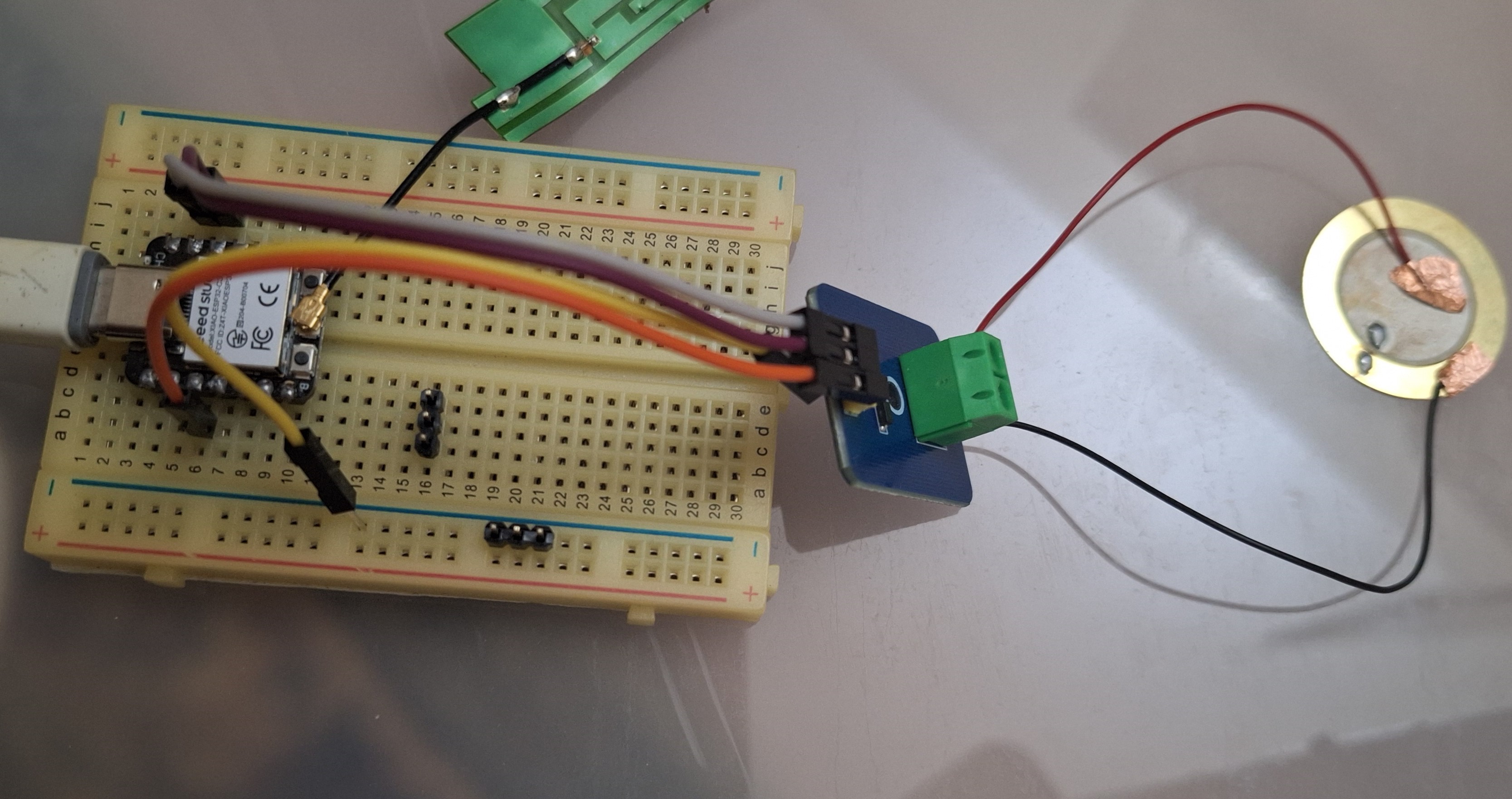
Test Setup
Objective:
Test the piezo sensor to determine the best threshold value to use when housed in the final project’s enclosure.
Threshold Value: 20
Test Measurements
| Test | Tap Intensity | Sensor Reading |
|---|---|---|
| 1 | No tap | 0 |
| 2 | Light tap | ~9 |
| 3 | Medium tap | ~200–600 |
| 4 | Strong tap | ~1000 |
| 5 | Tap inside enclosure | ~18-30 |
Observations
- Idle sensor reading:
0 - Light taps produced readings around:
5–20 - Strong taps produced readings around:
600–1000 - The threshold was set to
20because: it reliably detects tapping when it's inside the enclosure.
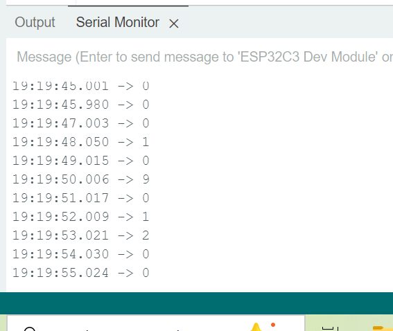
Test Images
Serial Monitor showing sensor readings
Final Demonstration
The completed input device successfully detects physical taps using the piezo sensor.
During testing:
- The sensor continuously measured analog values.
- Values below the threshold were ignored.
- Values above the threshold triggered a successful tap detection.
- The Serial Monitor confirmed that the input was correctly detected.
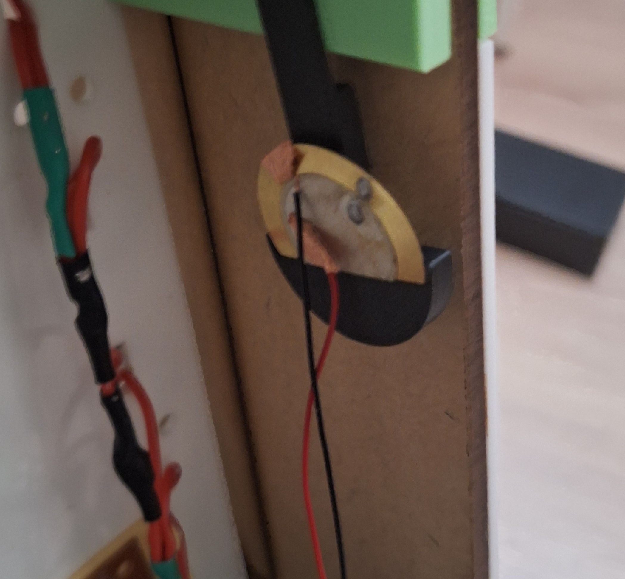
Demonstration Images
Successful tap detection
Complete hardware setup in the final project
⚠️ Problems & Solutions
Problem: Heat damage to the copper traces. During my first joint attempt, the copper foil lifted off the plastic substrate because the soldering iron tip stayed in contact with the trace too long. Solution: I stripped back the broken run, placed a small fresh strip of copper tape to bridge the gap, lowered the iron temperature to 280°C, and limited pad touch times to less than 2 seconds per joint.
🧩 Files
📝 Reflection
Testing the vinyl cutter as a rapid circuit board prototyping workflow was a huge eye-opener. While it requires extreme temperature discipline during manual soldering cycles compared to standard milled FR4 fiberglass substrates, it opens up awesome possibilities for creating flexible, low-profile custom input arrays that can adapt perfectly to curved final project enclosures.