Machine Design — Digital Adjustable Mannequin
A Multi-Axis Parametric Physical Mannequin
Group Assignment
- Design a machine that includes mechanism + actuation + automation + application
- Build the mechanical parts and operate it manually
- Document the group project
Full group documentation can be found on our Lab Group Page.
1.0 Introduction
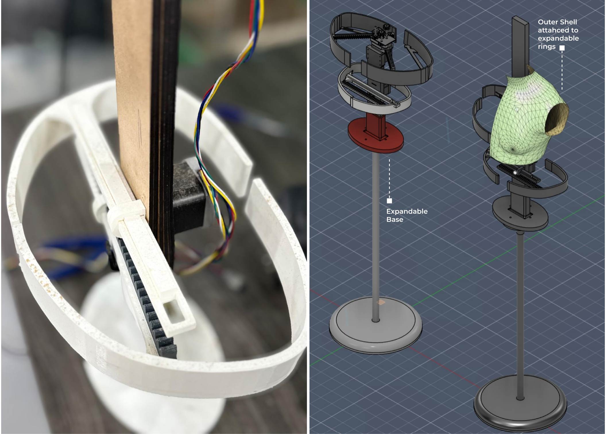
For Machine Week, our team designed and fabricated a digital adjustable mannequin that can change its dimensions to accommodate different body sizes. The project combines mechanical systems, electronics, and digital fabrication techniques, using rack-and-pinion mechanisms driven by stepper motors to adjust the bust and waist measurements. Most components were produced through 3D printing and laser cutting, then assembled into a working prototype controlled through an Arduino-based interface. The project allowed us to explore the complete process of machine design, from concept development and fabrication to assembly, programming, and testing.
2.0 Design Rationale
The project was inspired by existing adjustable mannequins, which rely on manual mechanisms to alter body measurements. We wanted to expand on this concept by exploring how digital fabrication, electronics, and mechanical systems could be integrated into a digitally controlled mannequin capable of adapting its dimensions more precisely and efficiently for garment fitting and prototyping.
3.0 Project Planning
Project Management
The selection process focused on finding a project that maximized the use of digital fabrication while solving a real-world design constraint.
| Criteria | Mannequin Project | Alternative Idea |
|---|---|---|
| Complexity | High (Mechanical + Electronic) | Medium |
| Digital Mfg | 3D Printing, Laser, CNC, PCB | 3D Printing only |
| Modelling | High (Parametric & Kinematic) | Low |
| Scalability | High (Modular segments) | Medium |
| Usability | Professional Tailoring / Fashion | Hobbyist |
Final Decision: Digital Adjustable Mannequin.
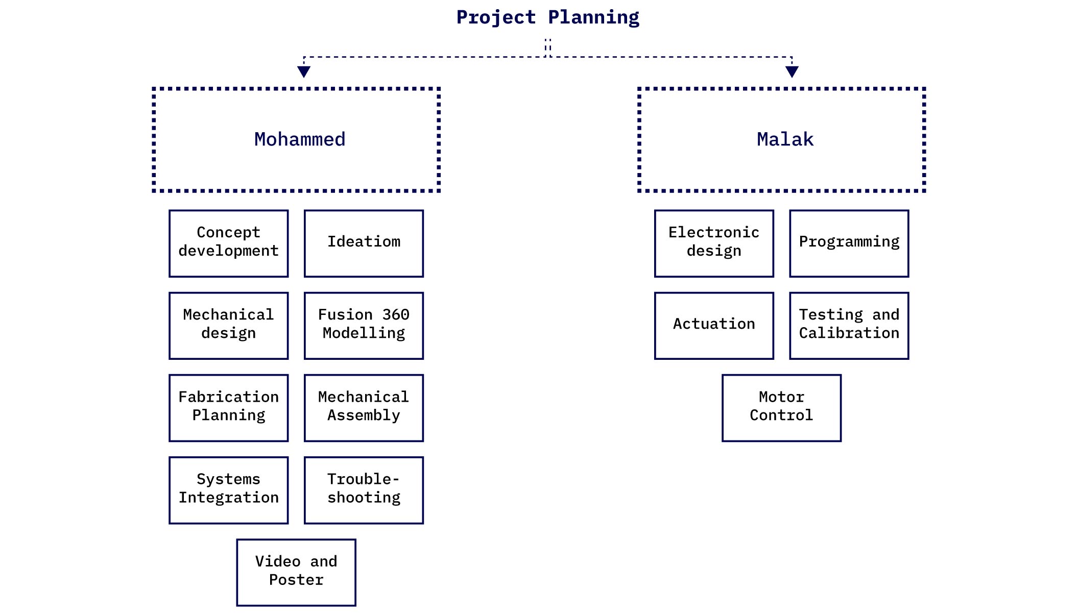
The project was divided between me and my team member Malak according to the main disciplines involved. I led the conceptual development of the project, including ideation, mechanism selection, mechanical design, CAD modeling, fabrication planning, and final mechanical assembly of the prototype.
Malak was responsible for the electronic design and automation aspects, including component selection, programming, motor control, and actuation testing. Throughout the project, design decisions were coordinated collaboratively to ensure seamless integration between the mechanical and electronic systems.
Roles and Responsibilities
| Concept and Design | Mohammed Azizi |
| Electronics and Wiring | Malak Al-Sharqawi |
| Video and Poster | Mohammed Azizi |
| Documentation | Collaborative |
Scope
The project aims to create a functional prototype focusing on three primary body measurements: Waist, Bust, and Neck/Shoulders, with its initial version solving for Waist and Bust mechanisms.
Bill of Materials (BOM)
| Category | Item | Description | Quantity |
|---|---|---|---|
| Motor Driver | Arduino Uno R3 | Main Microcontroller | 1 |
| CNC Shield V3 | Expansion Board | 1 | |
| A4988 Drivers | Stepper Motor Drivers | 2 | |
| Motors | NEMA 17 | Stepper Motors (3 total) | 2–3 |
| Input Devices | Rotary Encoder | With push button for menu navigation | 1 |
| Push Buttons | Tactile switches | 4 | |
| Limit Switches | End-stops for homing / calibration | 2–3 | |
| Display | 0.96" OLED Display | I2C Communication | 1 |
| Power Supply | 12V Power Supply | Dedicated for Motor Rail | 1 |
| USB / 5V Cable | Logic power for Arduino | 1 | |
| Filament | PLA | Structure & Shell | ~1 kg |
| PETG | Gears & High-Load Parts | ~1 kg | |
| Lead Screws | T8 8mm | With Brass Nuts | 3 |
4.0 Mechanical Design
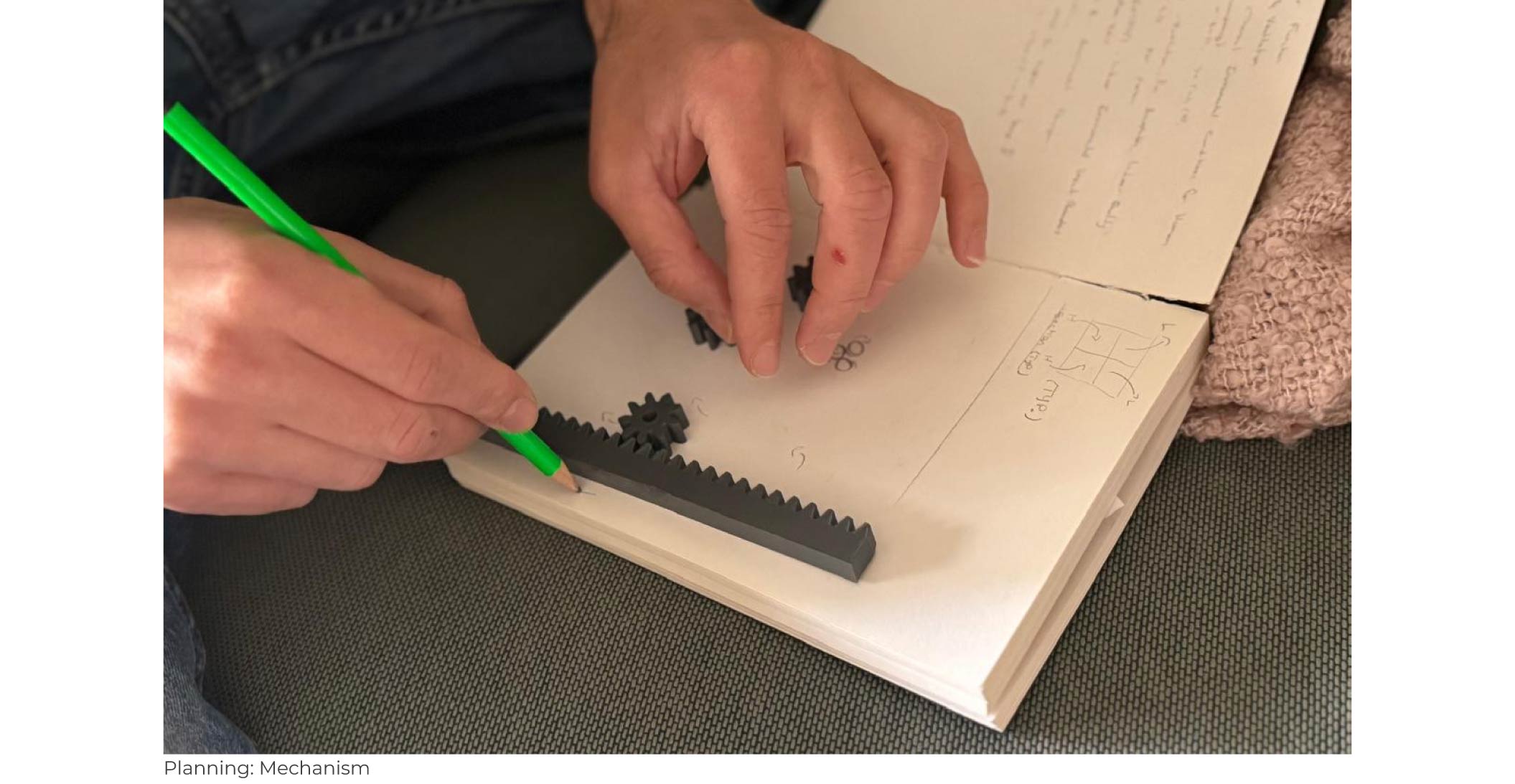
Mohammed Azizi — Mechanical LeadThe mechanical design was inspired by the expansion mechanism. After studying existing manual models, the idea was developed into a motorized system capable of achieving synchronized and uniform dimensional adjustments. A single stepper motor was used as the primary actuator, driving an opposed rack-and-pinion mechanism that moves two links simultaneously in opposite directions. This balanced configuration ensures symmetrical force distribution and smooth motion, allowing the mannequin's outer panels to expand uniformly while maintaining stability and accuracy.
Shell / Skeleton Components
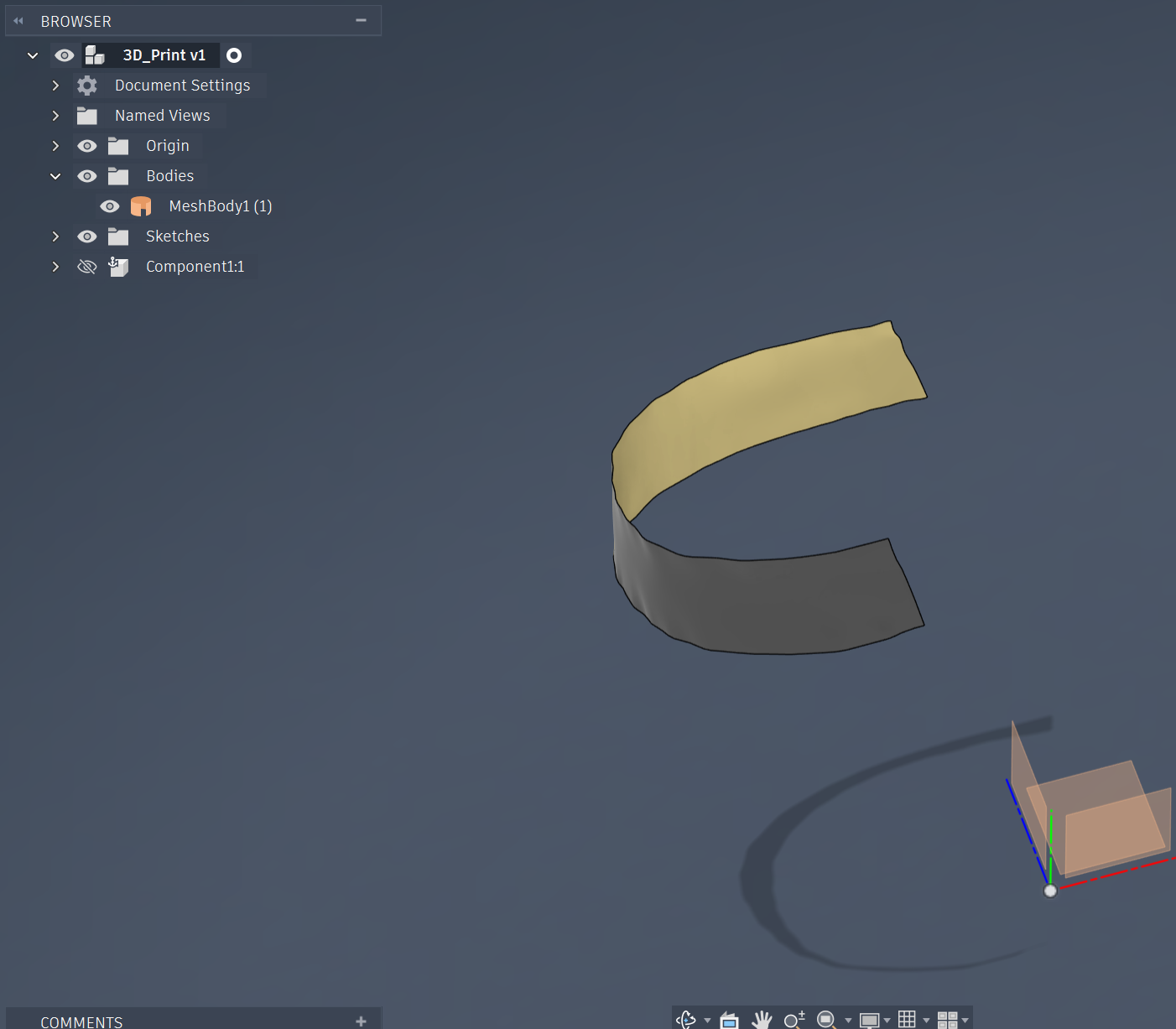
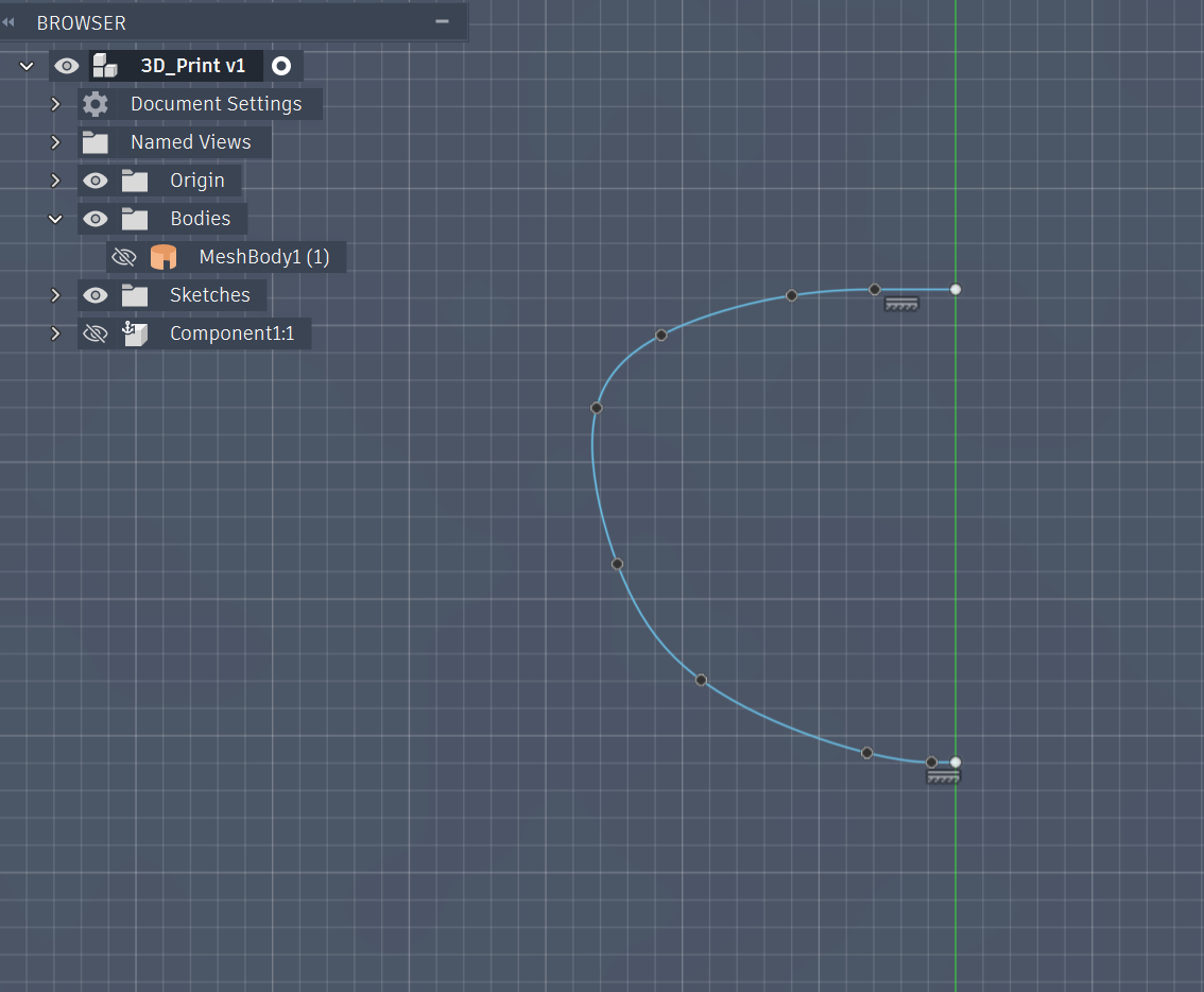
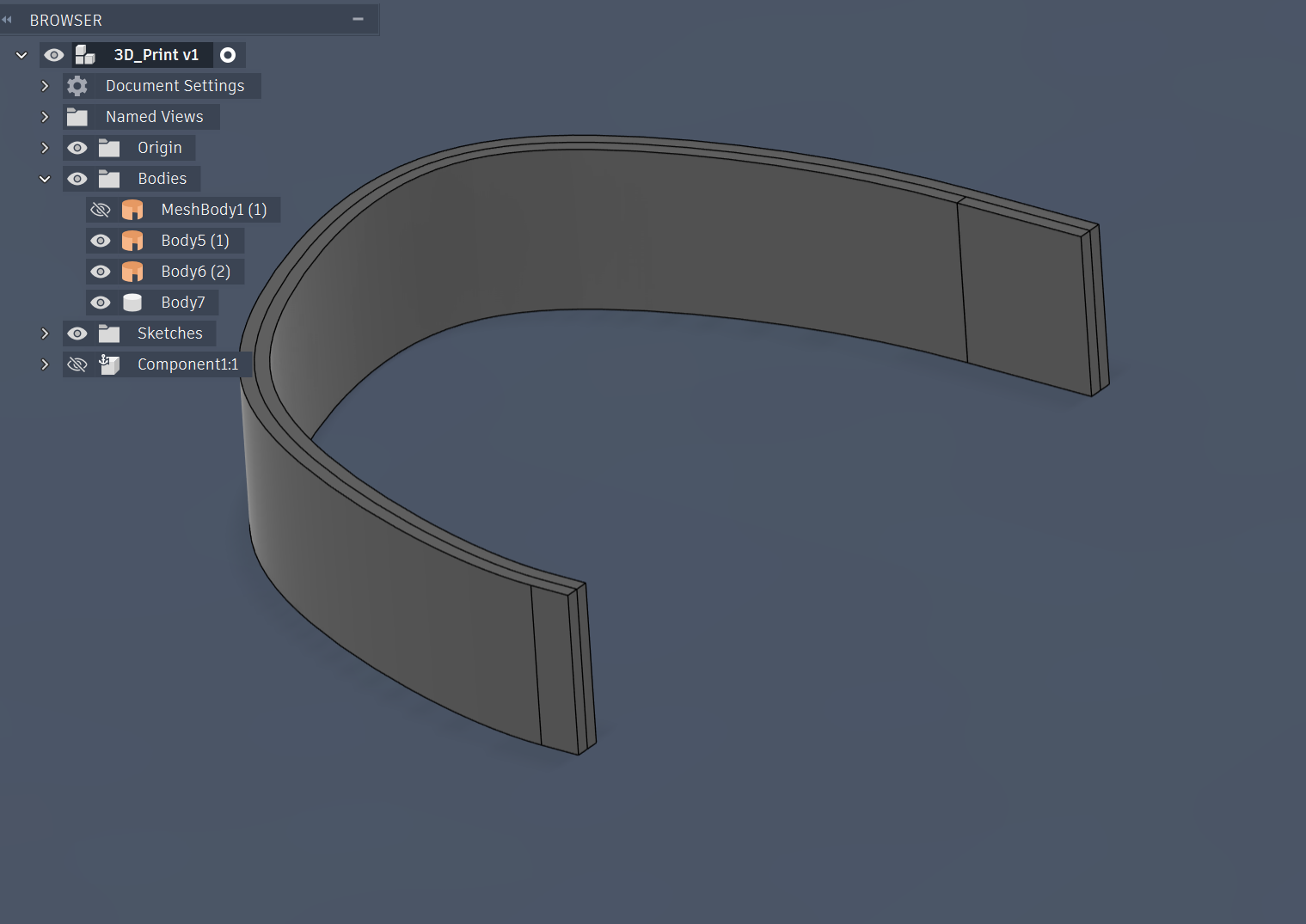
The Waist Mechanism
The Mannequin Base and Column
Bust Mechanism (Radial Expansion Mechanism)
5.0 Design and Modelling
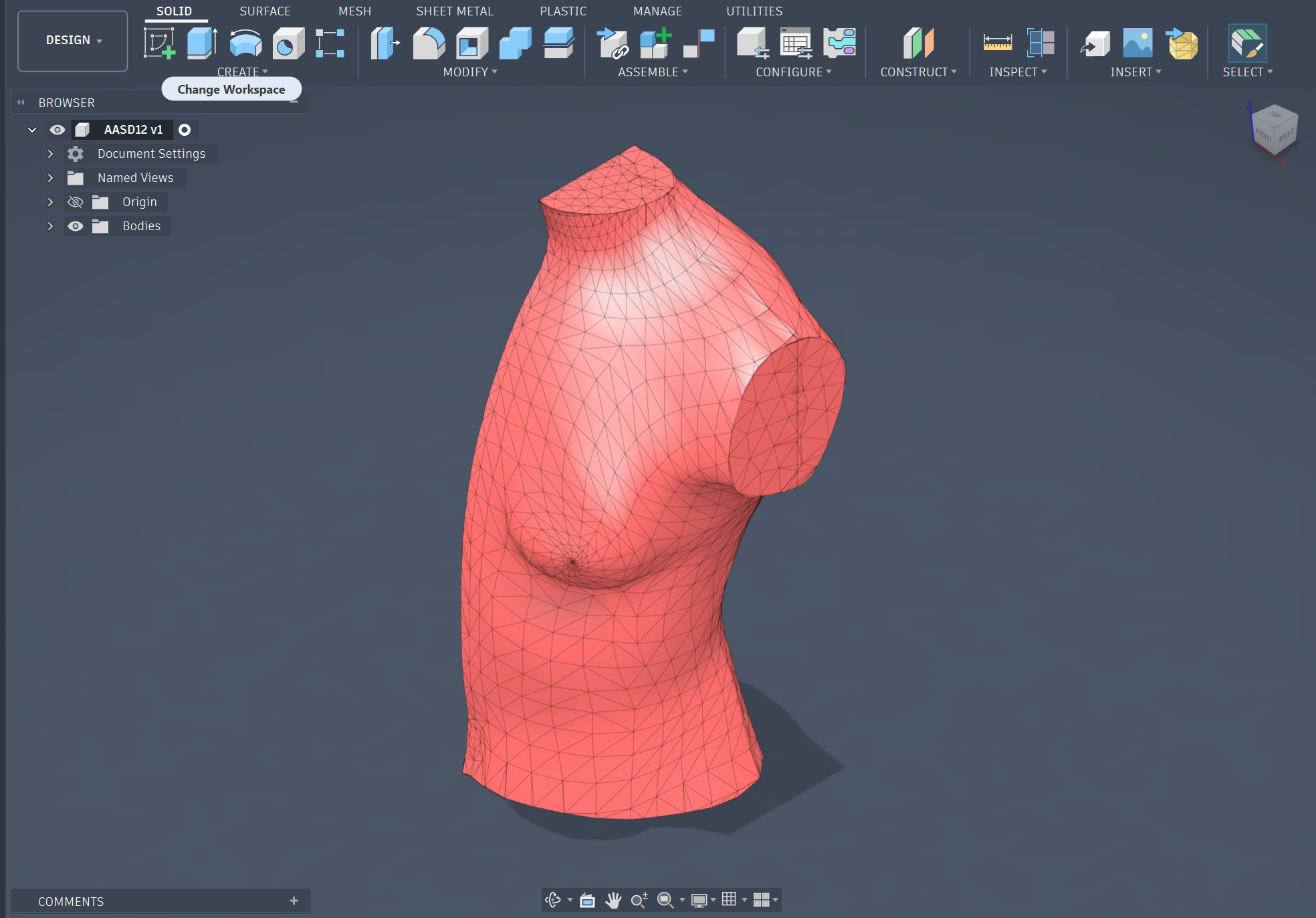
Mohammed Azizi — CAD & Modelling Lead- Human Model Generation: A baseline body model was created in MakeHuman using target body measurements and exported as a low-polygon mesh.
- Fusion 360 Conversion: The mesh was imported into Fusion 360 and converted into a solid body suitable for parametric modeling and mechanical integration.
- Parametric Chassis Design: A central mechanical structure was developed using user-defined parameters to control expansion distances, gear dimensions, and clearances.
- Rack-and-Pinion Mechanism: A radial rack-and-pinion system was designed to convert motor rotation into synchronized linear movement for uniform mannequin expansion.
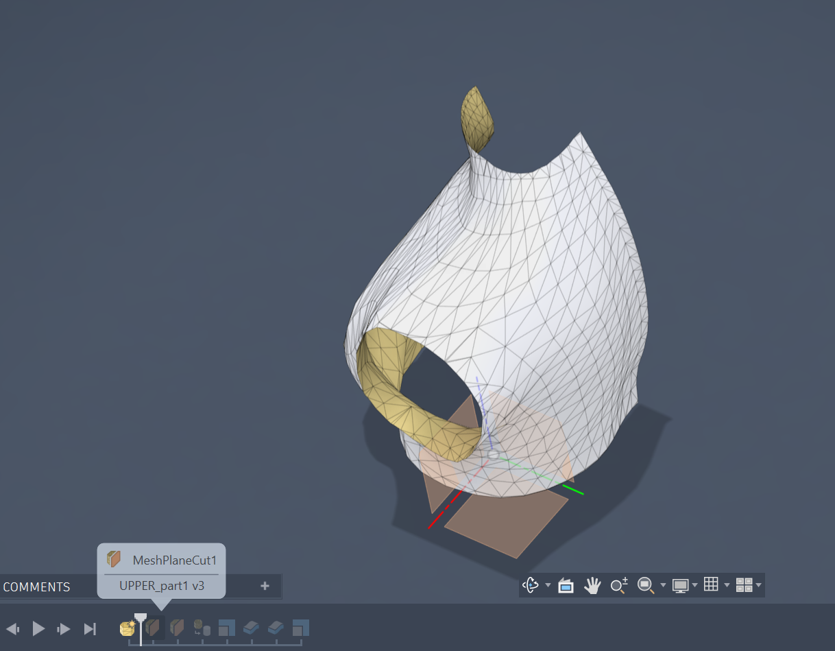
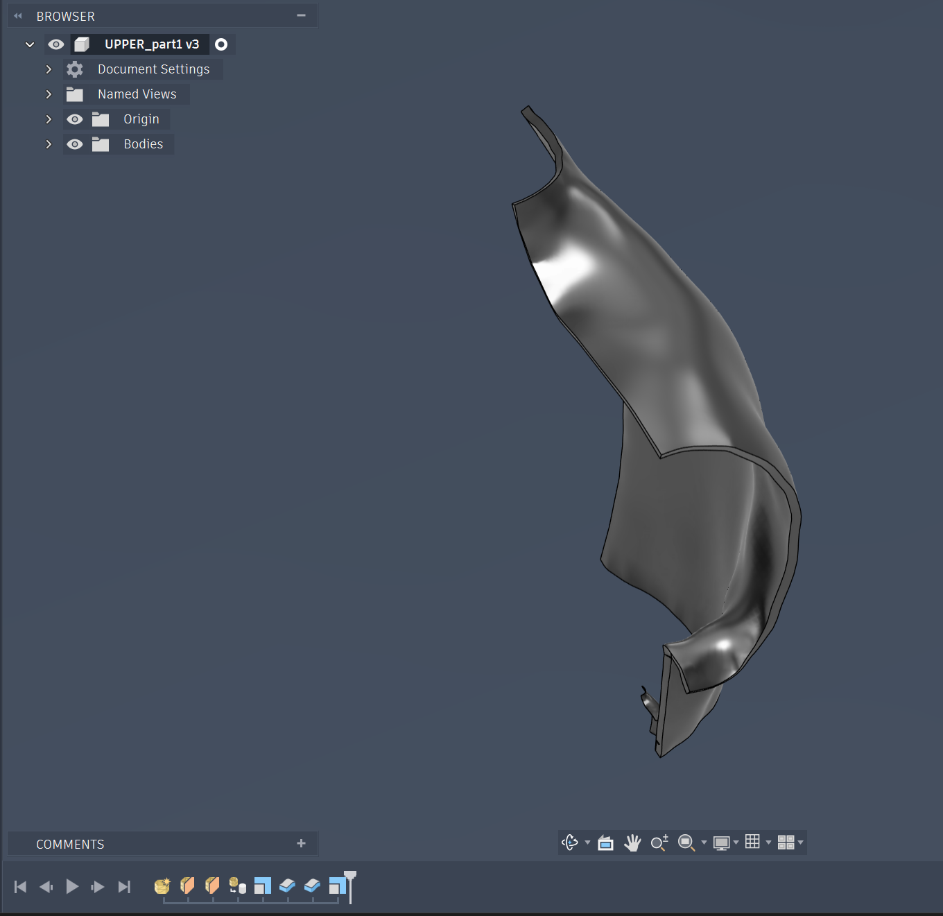
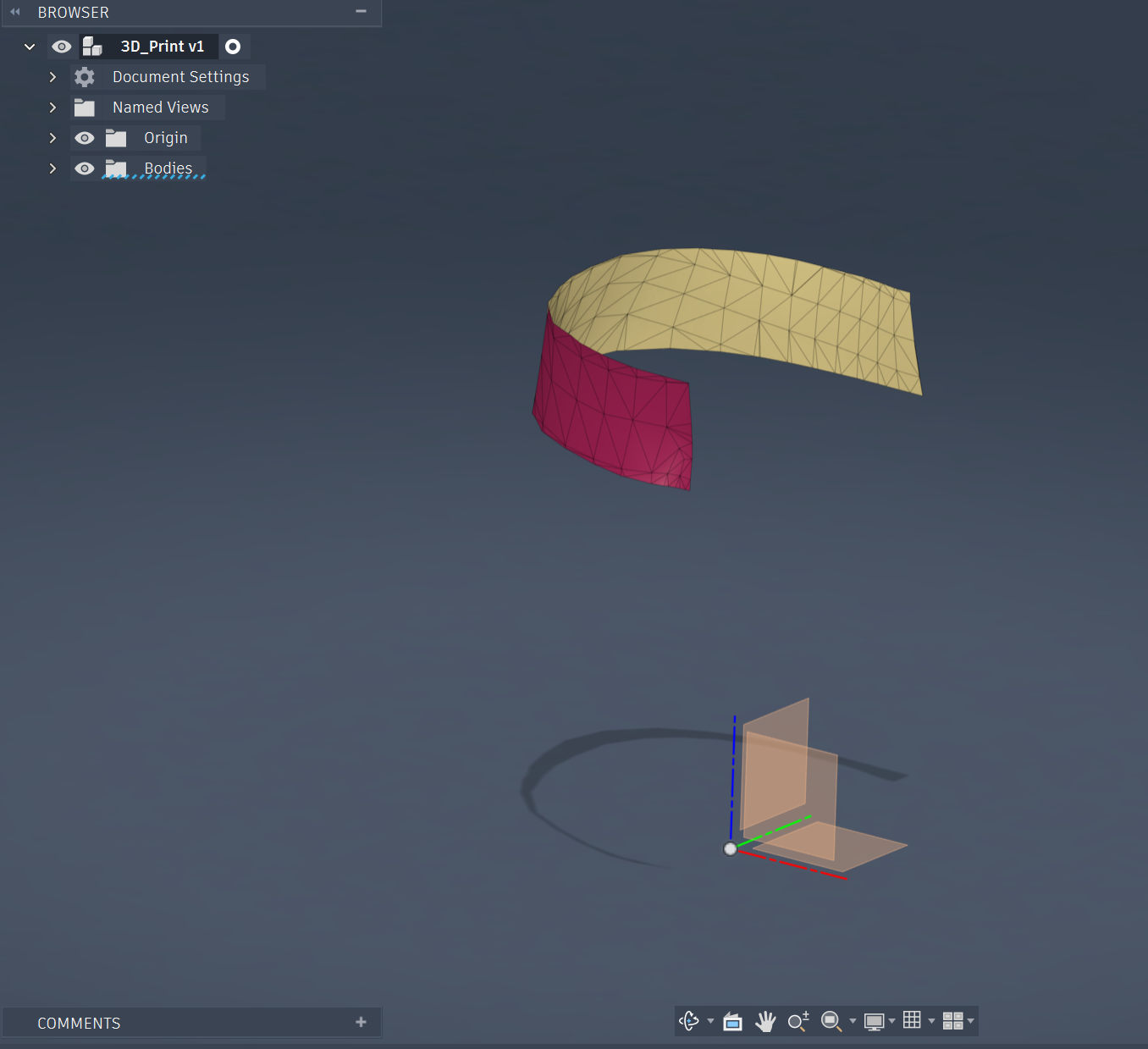
- Body Segmentation: The torso geometry was divided into separate shell panels and hollowed to create lightweight, movable sections connected to the mechanical system.
- Assembly and Simulation: Joints and motion links were applied to simulate expansion and verify smooth synchronized movement of all components.
- Manufacturing Preparation: Structural components were prepared for laser cutting, while gears, racks, and shell panels were exported for 3D printing and final assembly.
Sub-Assembly 1: The Base and Column
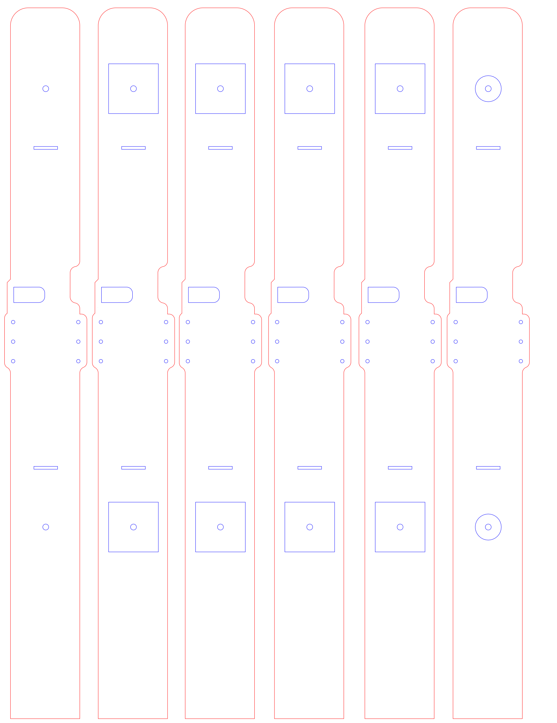
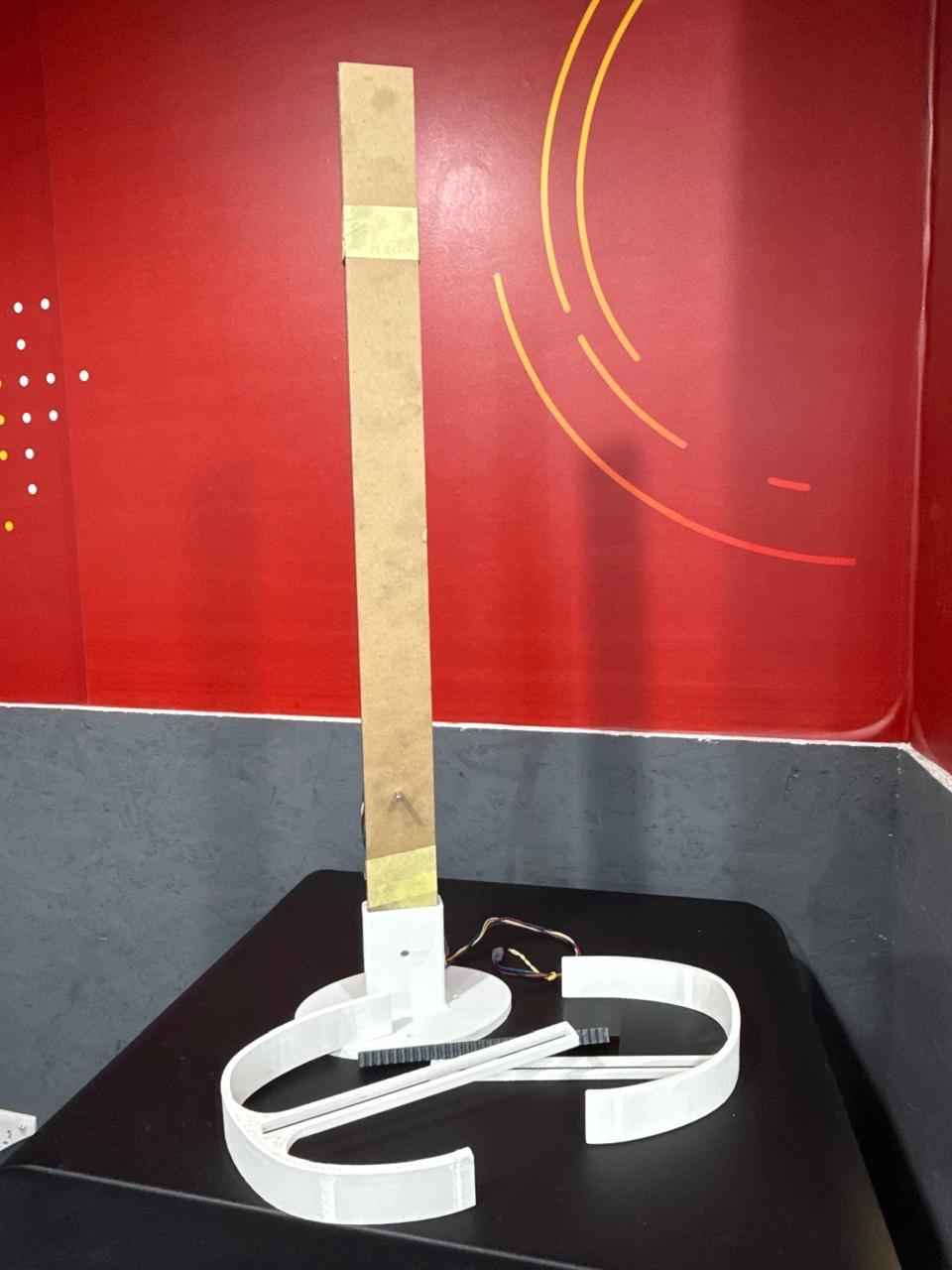
The first components modelled and manufactured with minimal changes were the mounting base of the mannequin and the column.
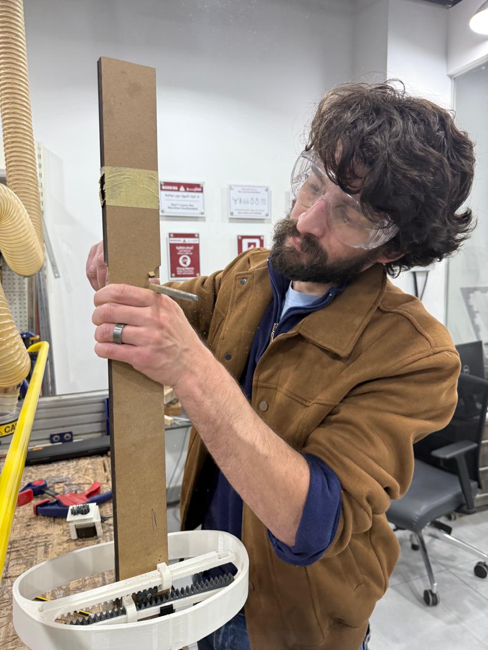
While the base (AM_Base) remained unchanged during the design and manufacturing process, the column went through two main iterations: the first was the column was laser cut to 70–75 cm in total length which was oversized. Also, after assembling the bust sub-assembly, as-built modifications were made and reflected in the model.
Sub-Assembly 2: The Waist Mechanism
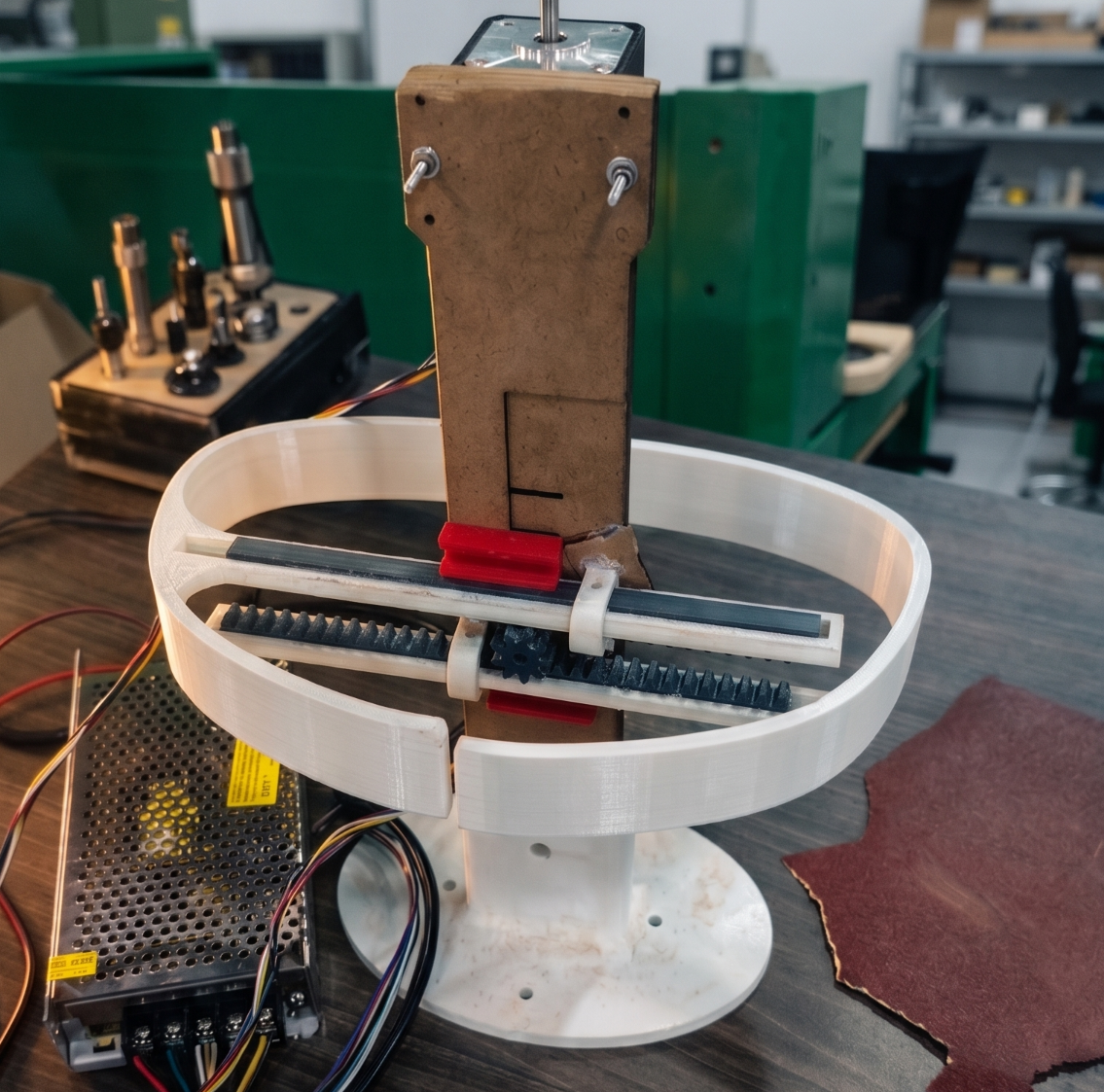
Following the iterations explained earlier, the final waist mechanism sub-assembly consisted of two racks, one gear, one stepper motor (sunk into the column), and two 3D-printed right and left waist pieces.
It can be seen in this model that the upper bust mechanism is still not in its final version, where it consisted of a central (long) gear controlling the motion of 4 racks, which ultimately failed.
The Bust Mechanism
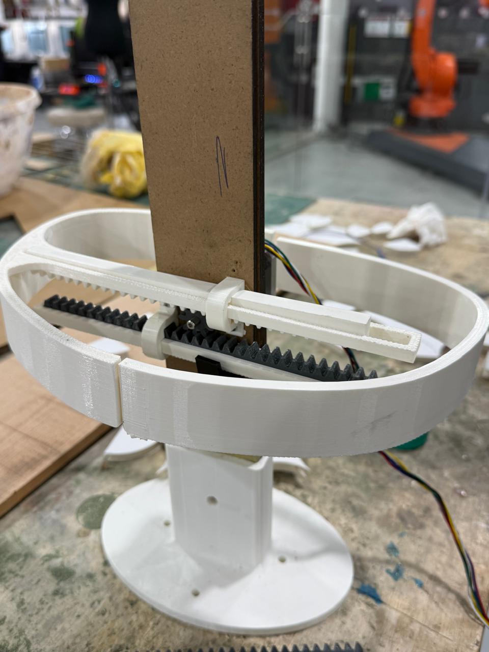
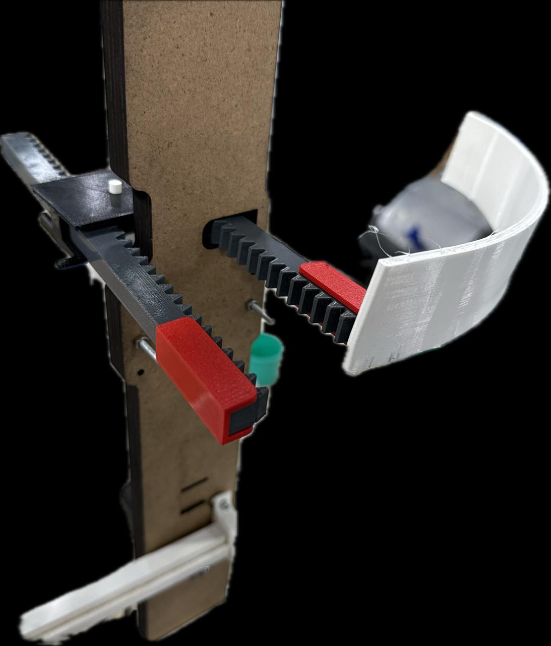
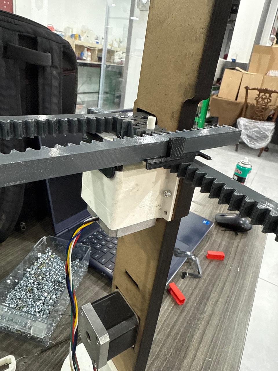
This was the main challenge of this project, as I spent a heavy amount of time trying to create a mechanism which needs to expand in a synced fashion to expand 4 separated pieces for the bust: left, right, front, and back pieces. I was inspired by the radial expansion mechanisms found in brake discs, with a modification to adapt the design to take the asymmetry of the mannequin and calculate the offsets and mounting positions for each link.
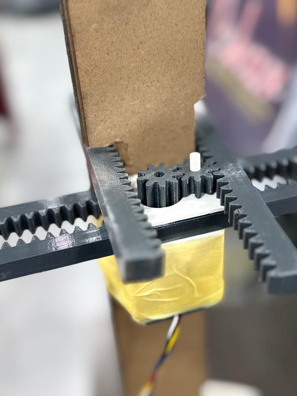
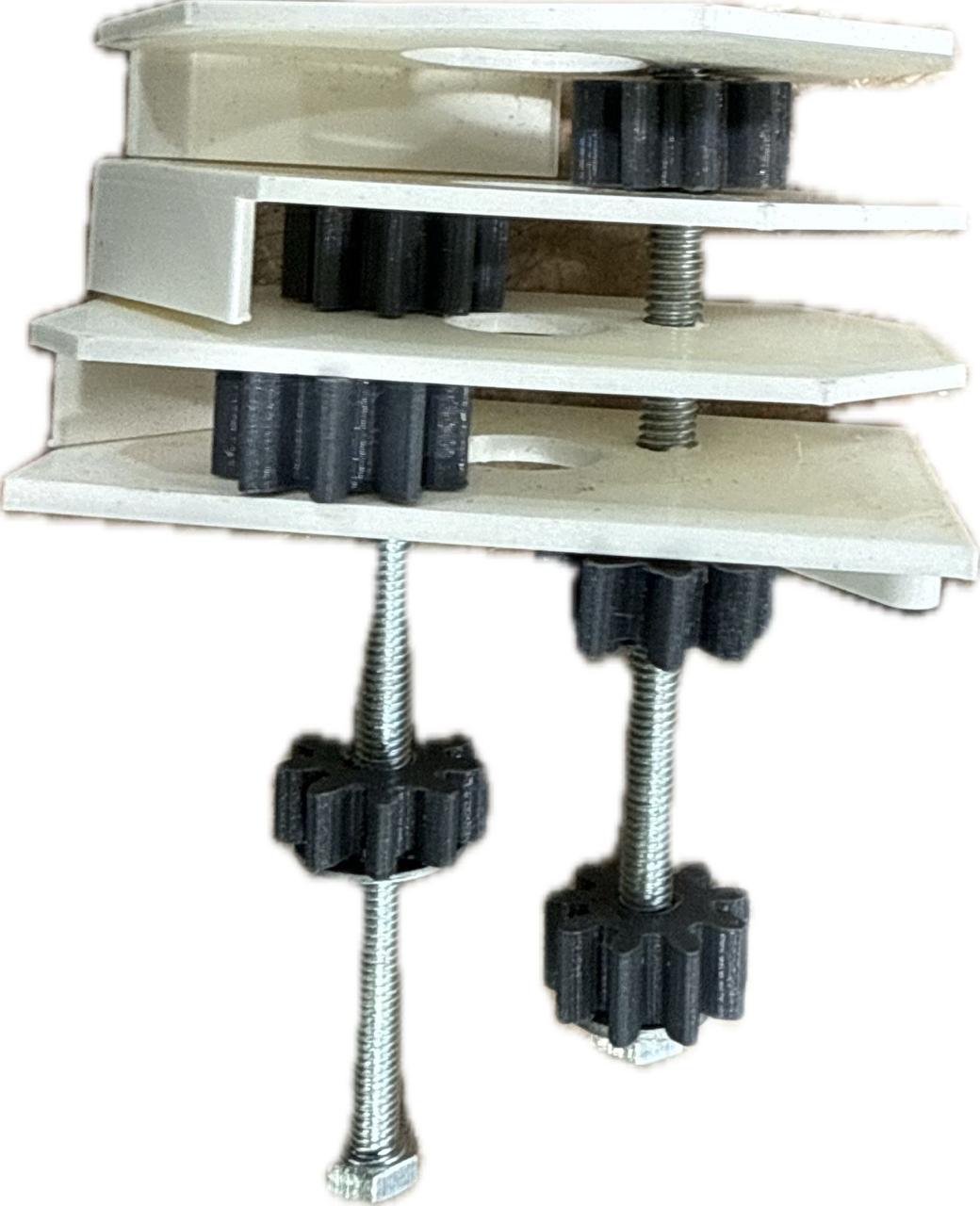
The center / beating heart of this mechanism was a tower gearbox with leveled gears, actuated by a center gear; each gear is on a level, all connected together as shown:
6.0 Manufacturing and Assembly
Mohammed Azizi — Fabrication LeadPhase 1: 3D Printing & Laser Cutting (Base, Gears, Racks, Waist Pieces)
The first phase was producing the 3D parts and the column (laser cut):
- The Base
- The Gears and Racks
- The Waist Pieces
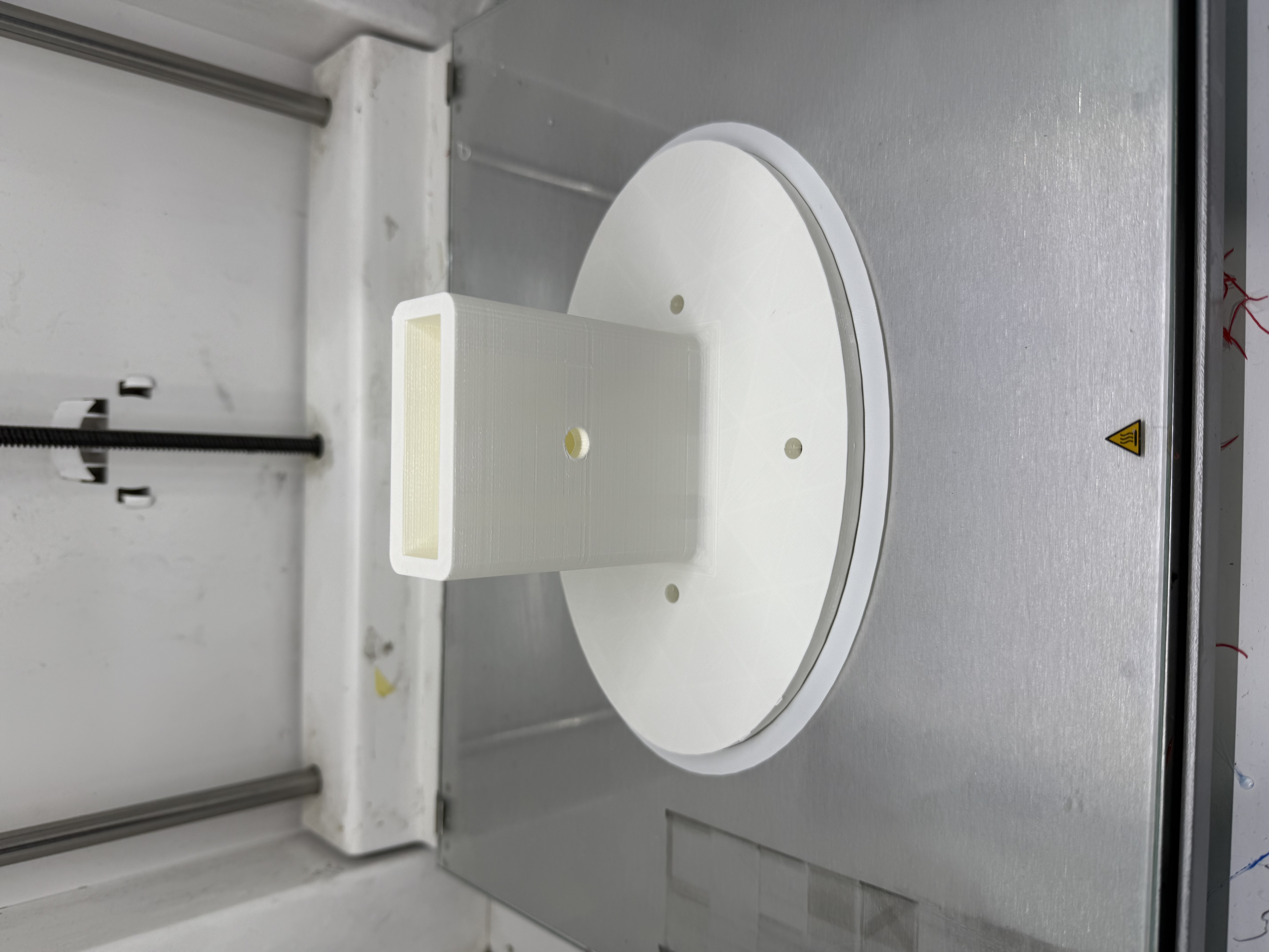
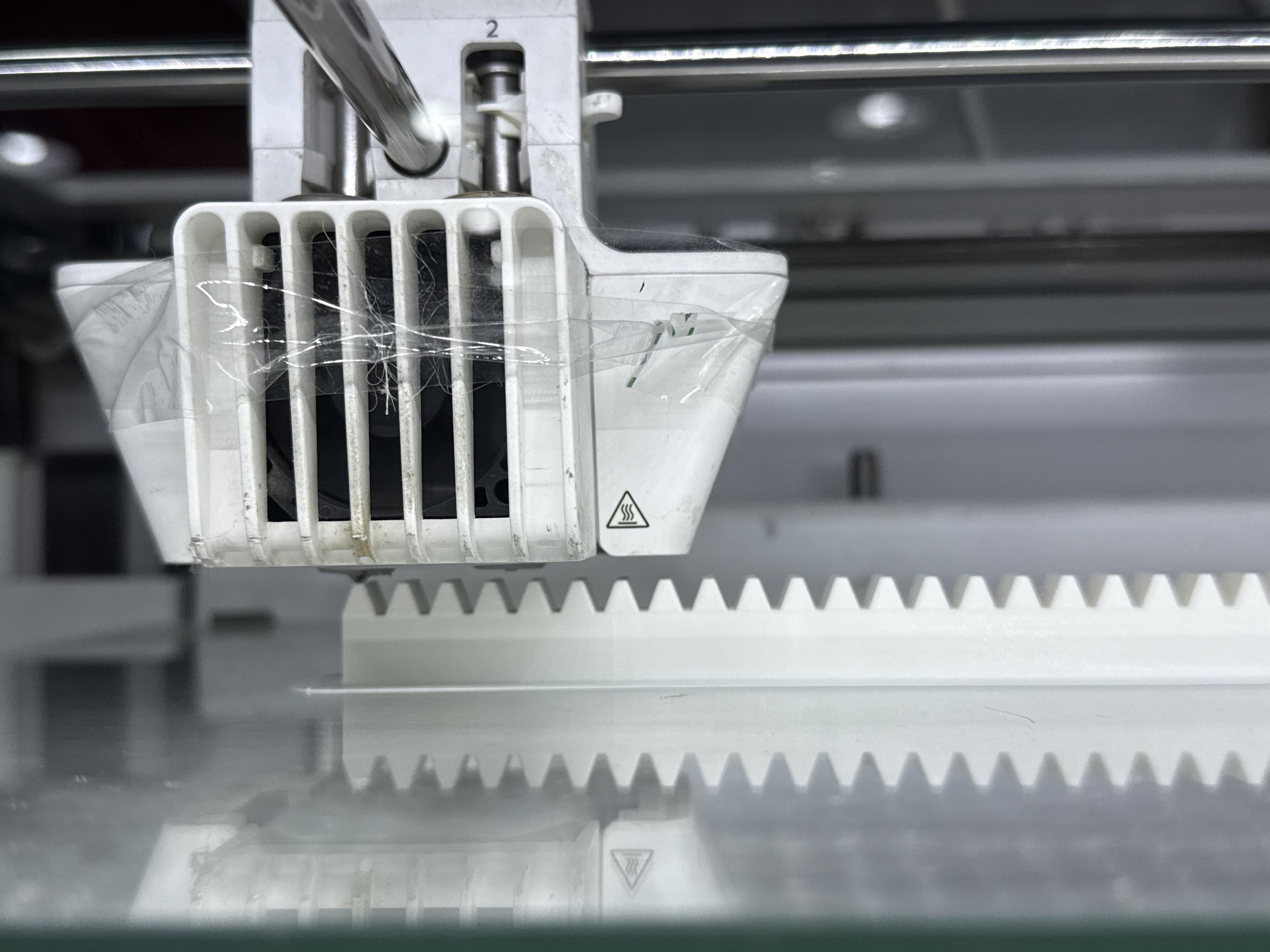
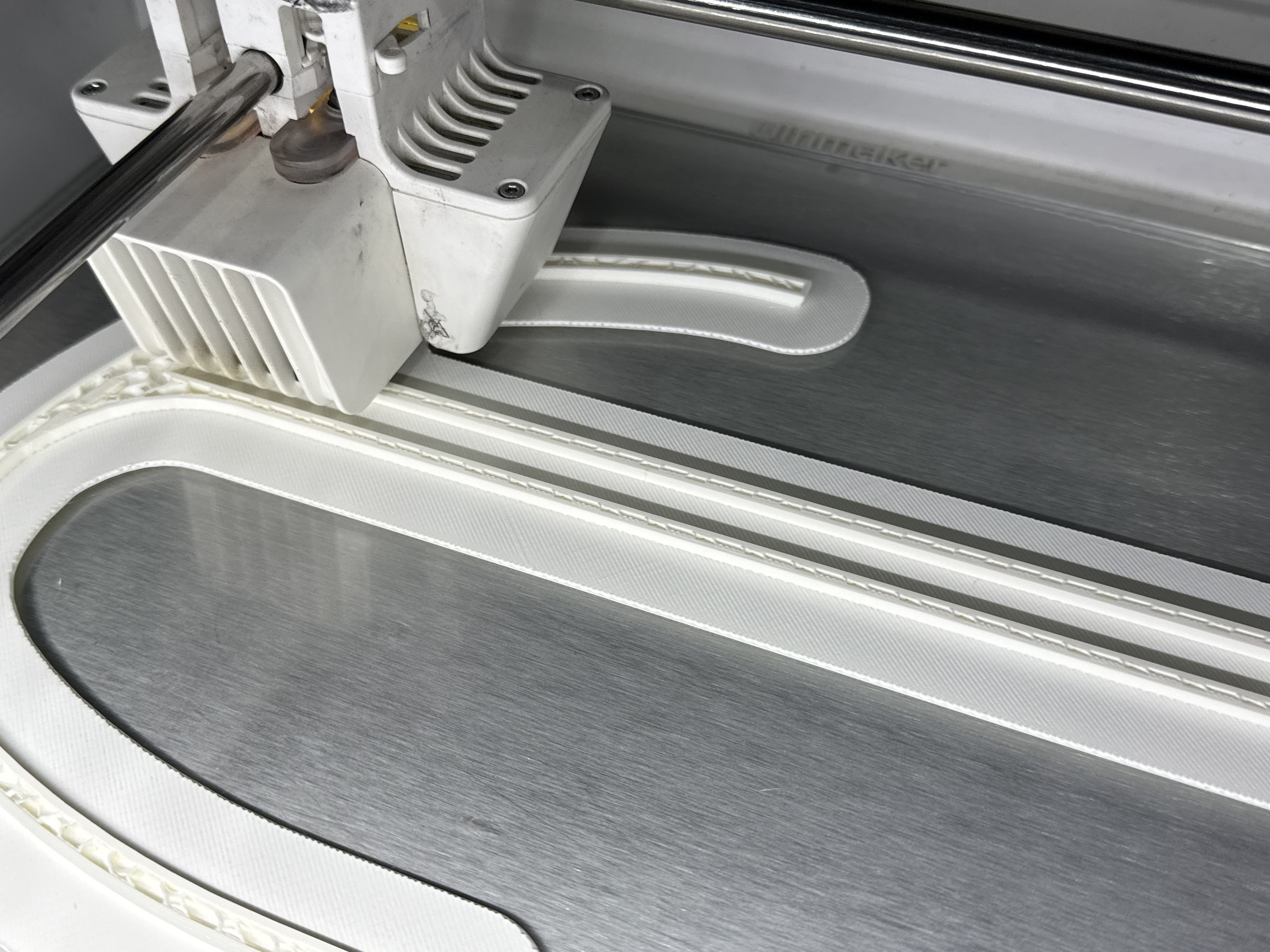
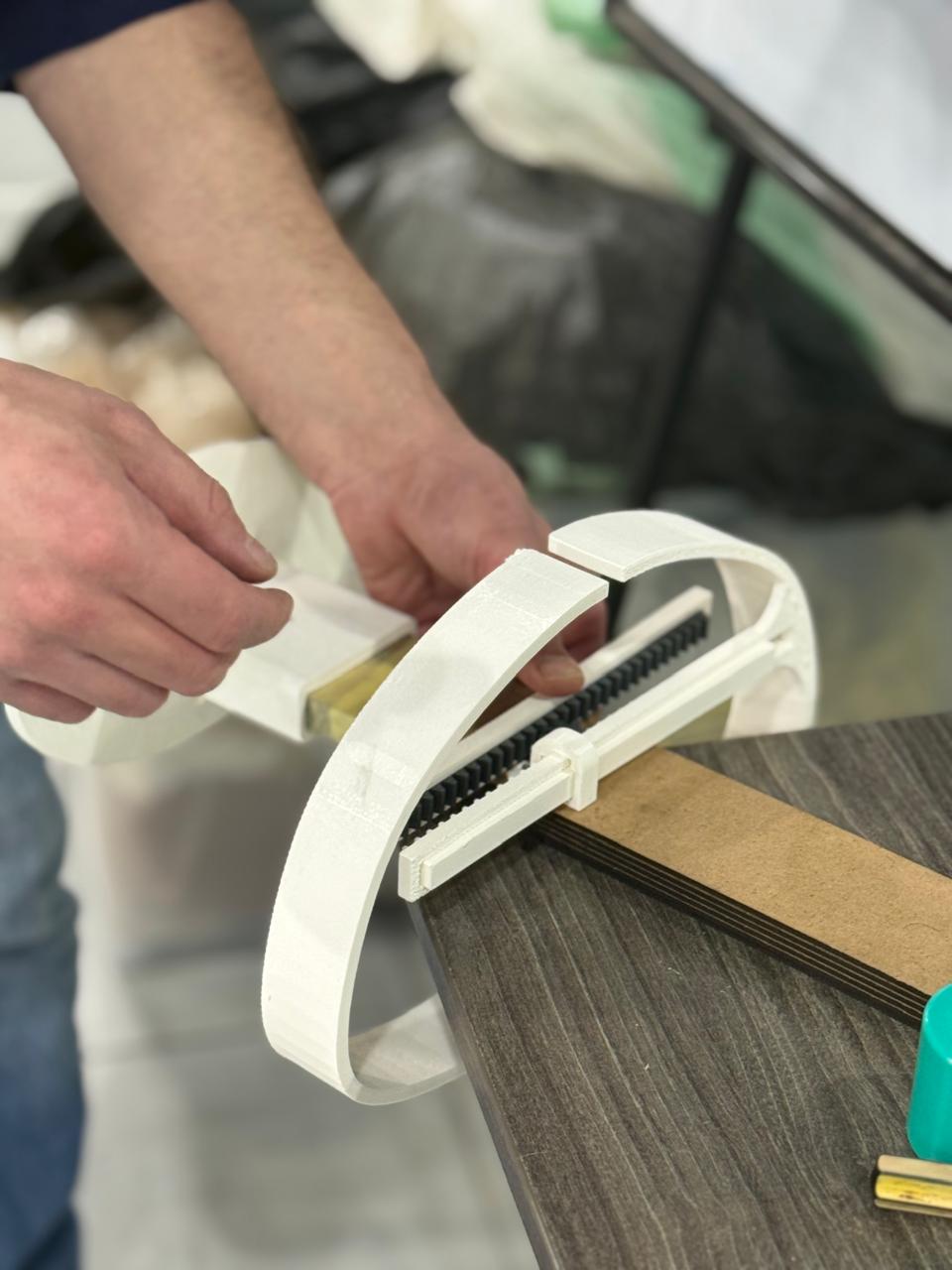
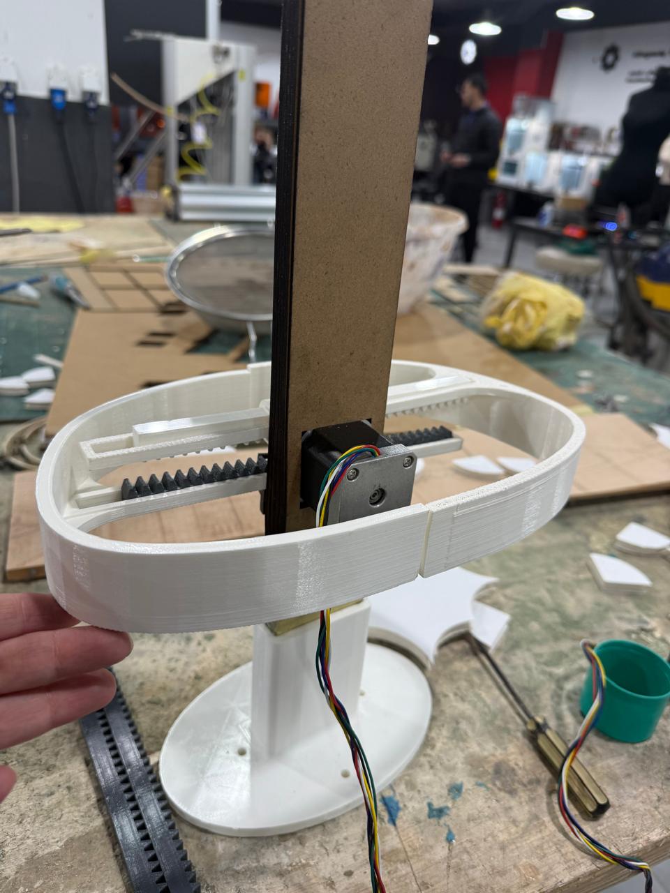
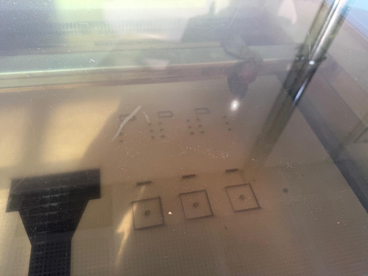
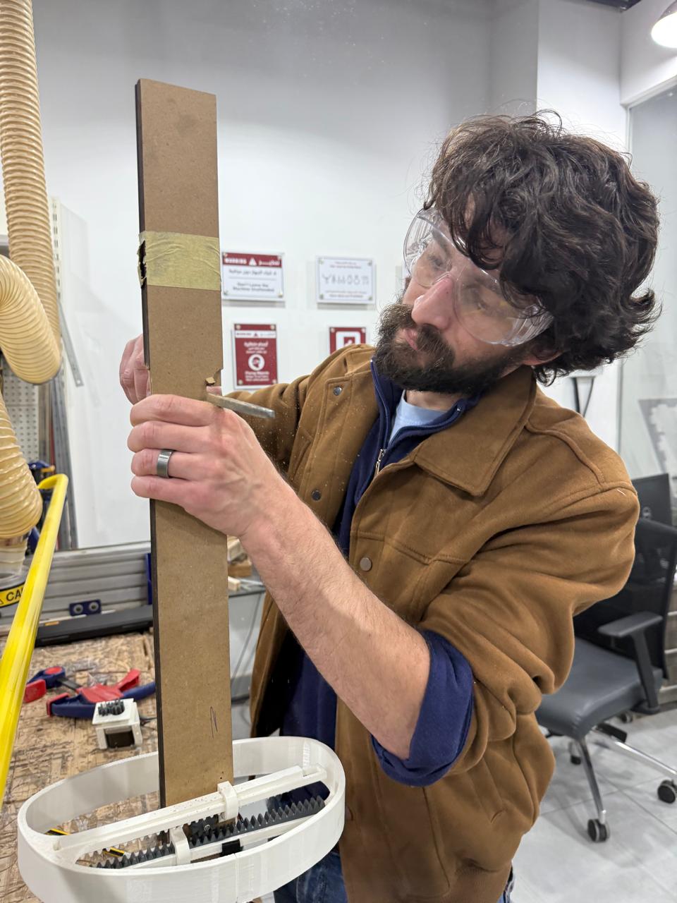
I utilized the laser cutter for the column instead of milling it to save time and to test multiple iterations more quickly — which resulted in two versions:
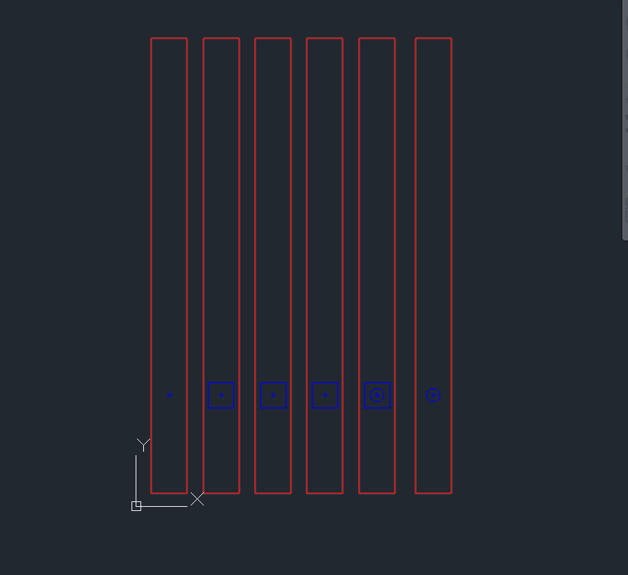
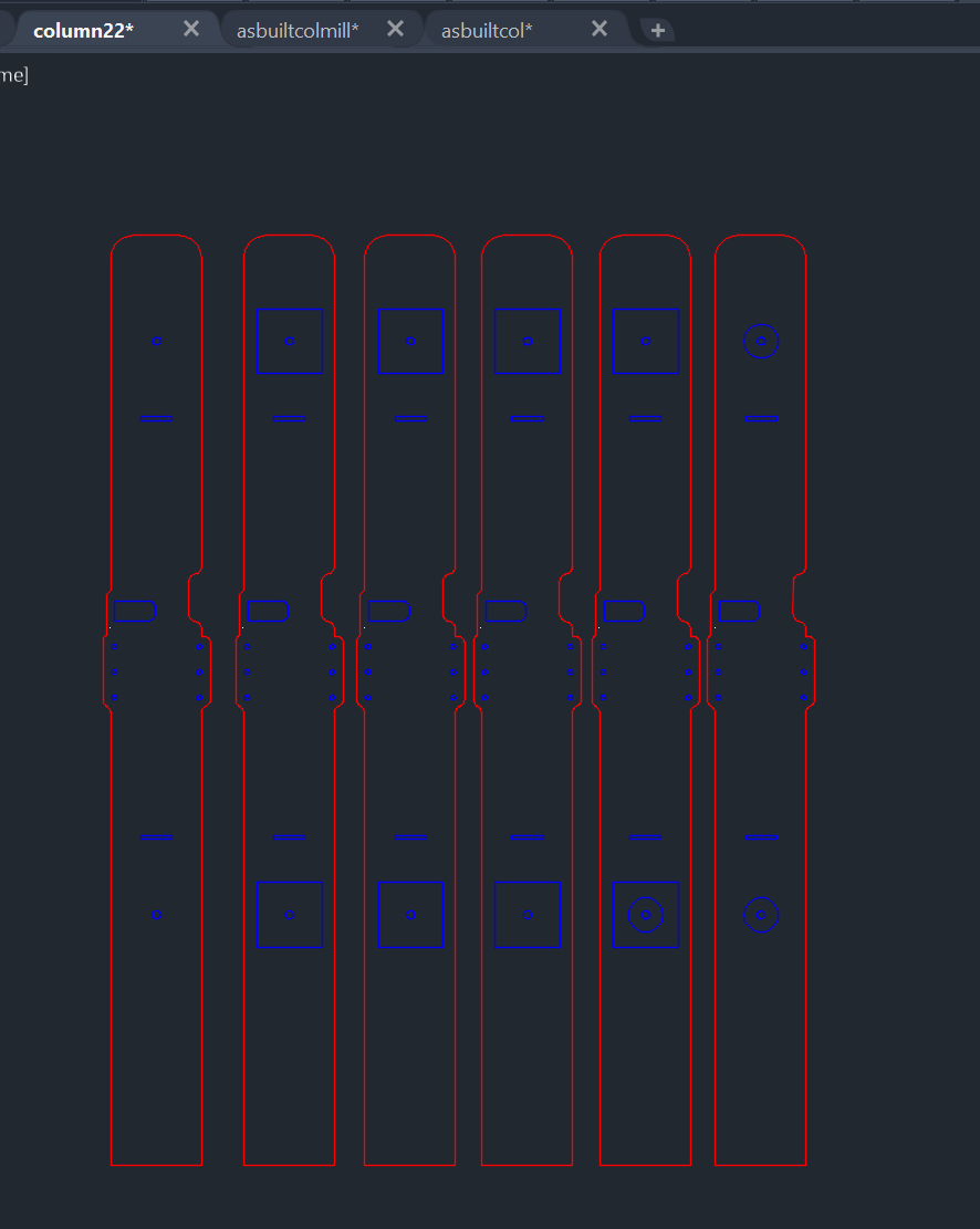
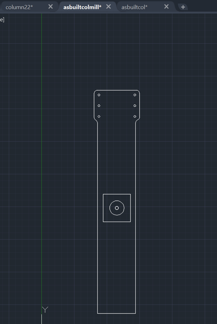
3D Component Testing
I printed various gears and racks to test material durability.
| Part | Material | Walls | Infill | Result |
|---|---|---|---|---|
| External Shell | PLA | 2–3 | 5–15% | Success (Lightweight) |
| Primary Gear | PETG | 4–6 | 5–50% | Success (High Torque) |
| Racks (PETG) | PETG | 4 | 5% | Success |
| Racks (PLA) | PLA | 4 | 5% | Success |
| Rack Gear | PLA | 4 | 30% | Failed (Brittle teeth) |
| Rack Gear | PETG | 2 | 5% | Failed |
I used the GF Gear Generator plugin to model my racks and gears. The parameters used:
Pinion Gear- Module (m): 1 mm
- Number of teeth (z): 20
- Pressure angle: 20°
- Pitch diameter: 20 mm
- Tip (addendum) diameter: 22 mm
- Root (dedendum) diameter: 17.5 mm
- Addendum: 1 mm | Dedendum: 1.25 mm | Clearance: 0.25 mm
- Face width: 10 mm
- Bore diameter: ~4.95 mm | Hub OD: ~13 mm
- Total part length: 42.9 mm
- Module: 1 mm | Pressure angle: 20°
- Addendum height: 1 mm | Dedendum depth: 1.25 mm
- Tooth pitch: π × m ≈ 3.1416 mm
- Face width: ≥ 10 mm | Fillet radius: 0.38 mm
- Number of teeth: as required by travel distance
Phase 2: Bust Mechanism (First Iteration — Failed)
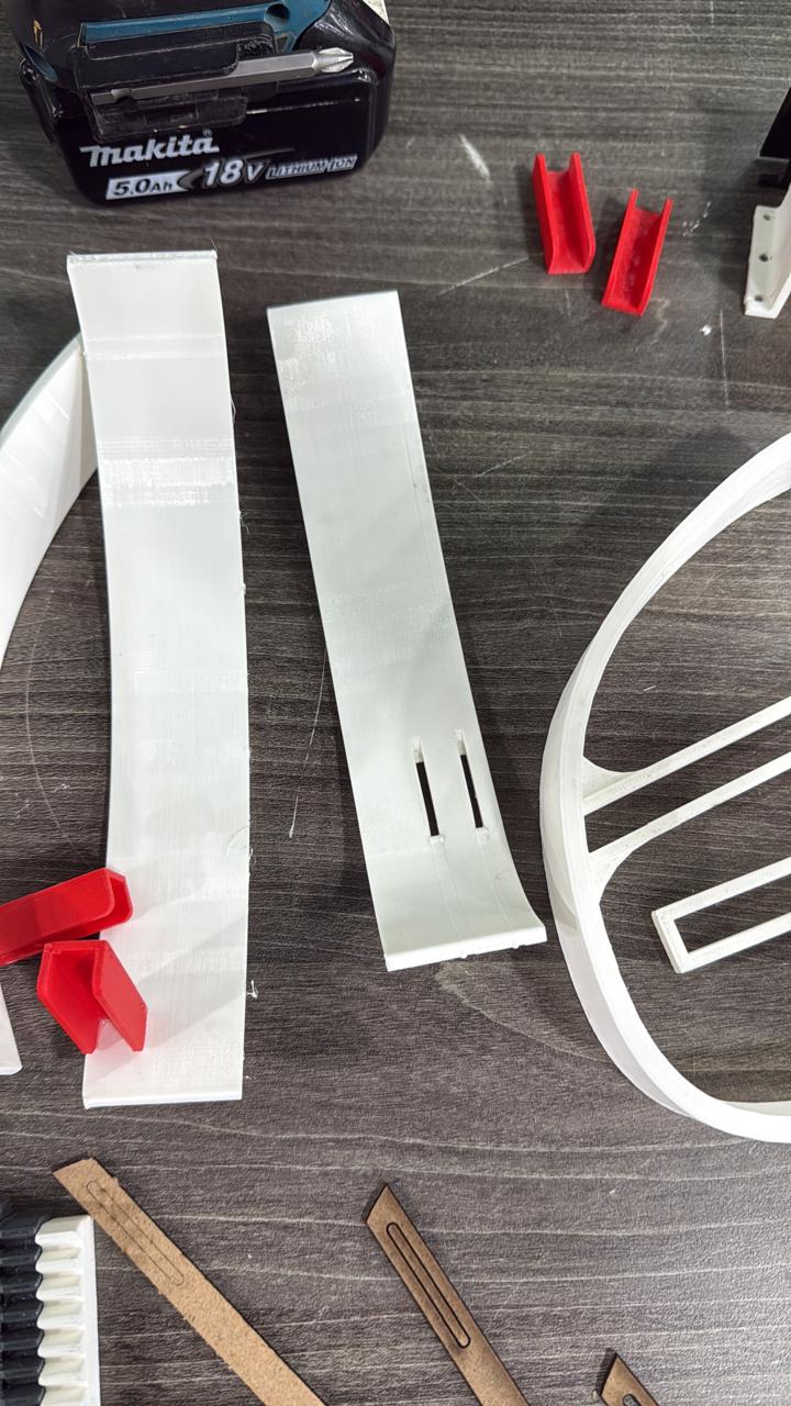
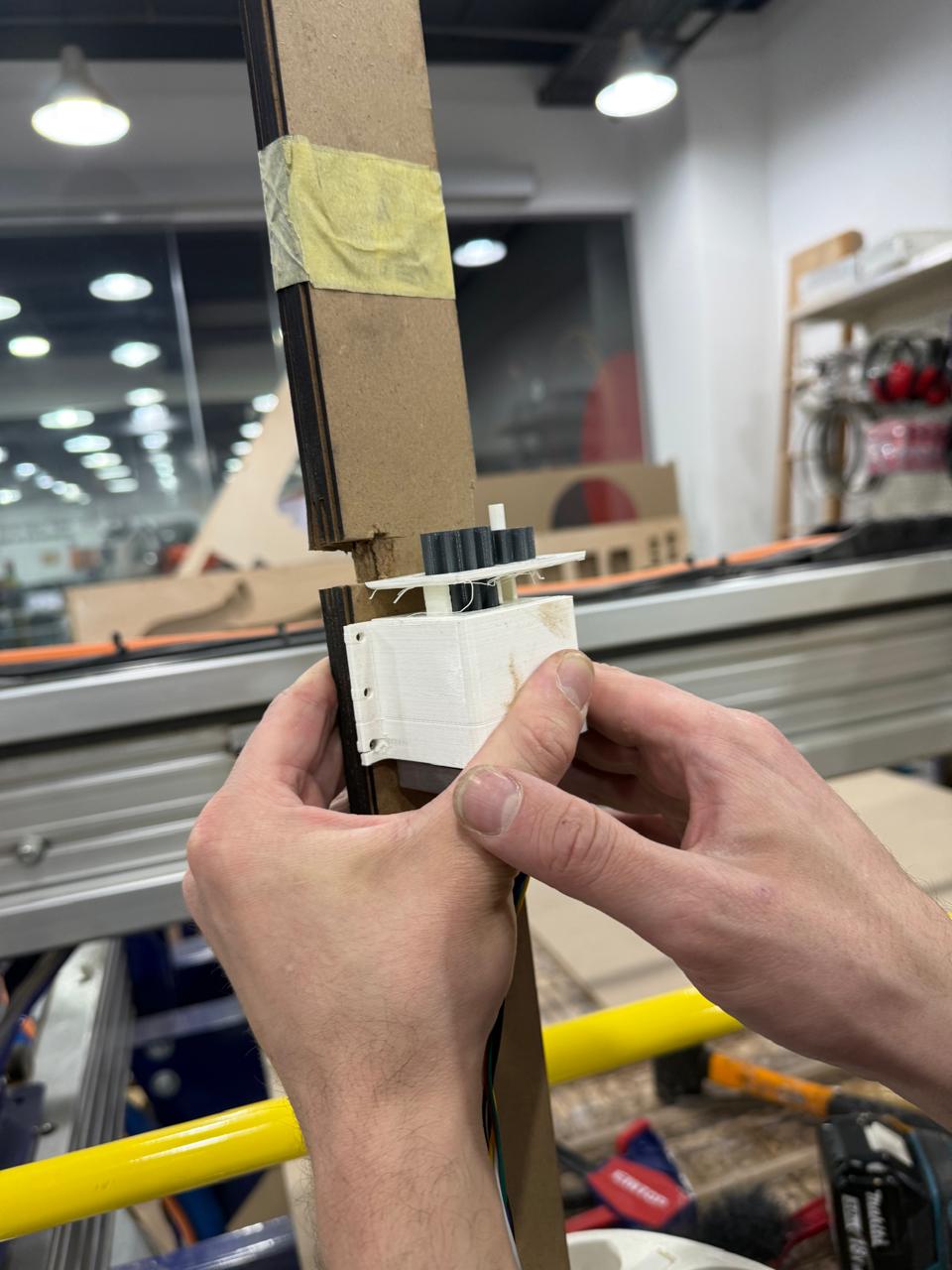
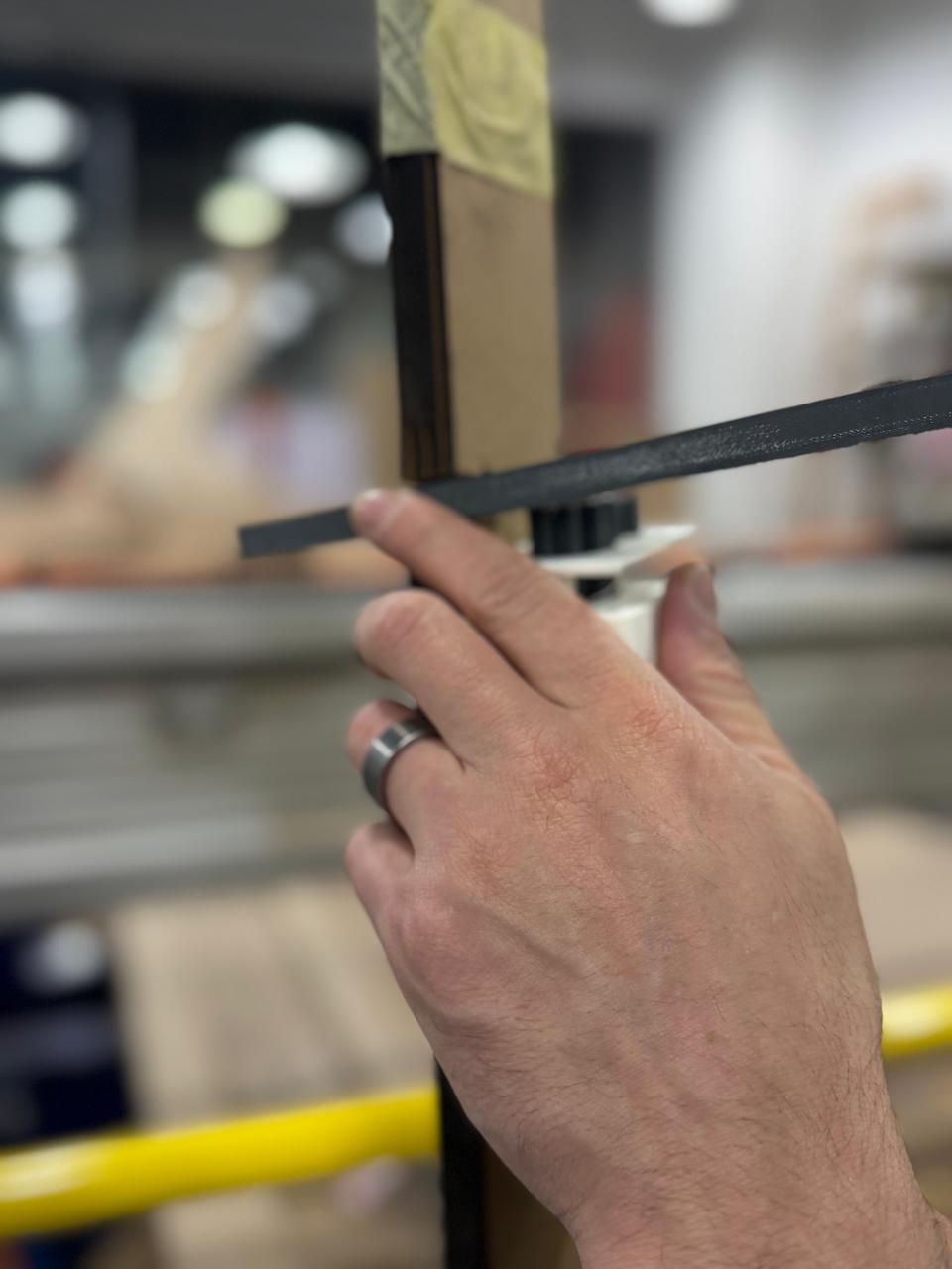
The second phase covered the bust mechanism. As mentioned earlier, the first iteration failed, but this phase was a mix of live modifications and reflecting outcomes on the model. Below are shots from this failed phase which led to the radial expansion mechanism development. This phase also covered the 3D printing of the motor vertical clamp base, which remained unchanged throughout the project.
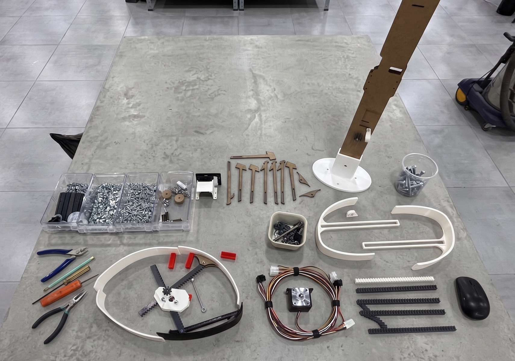
Final Part List for Revised Mechanism
7.0 System Integration (Mechanical and Automation)
Mohammed Azizi — Mechanical IntegrationIntegrating the mechanical chassis required careful alignment to bridge the gap between static 3D printed components and motorized automation. I focused on building the centralized structural framework, ensuring that the tolerances of the printed gears and laser-cut plates accommodated the physical mounting of the NEMA 17 stepper motors and limit switches without causing structural binding. This involved meticulously routing internal spacing for the wiring looms and establishing solid structural anchoring points, allowing the physical mechanism to reliably translate high-torque motor rotation into fluid, multi-axis panel expansion.
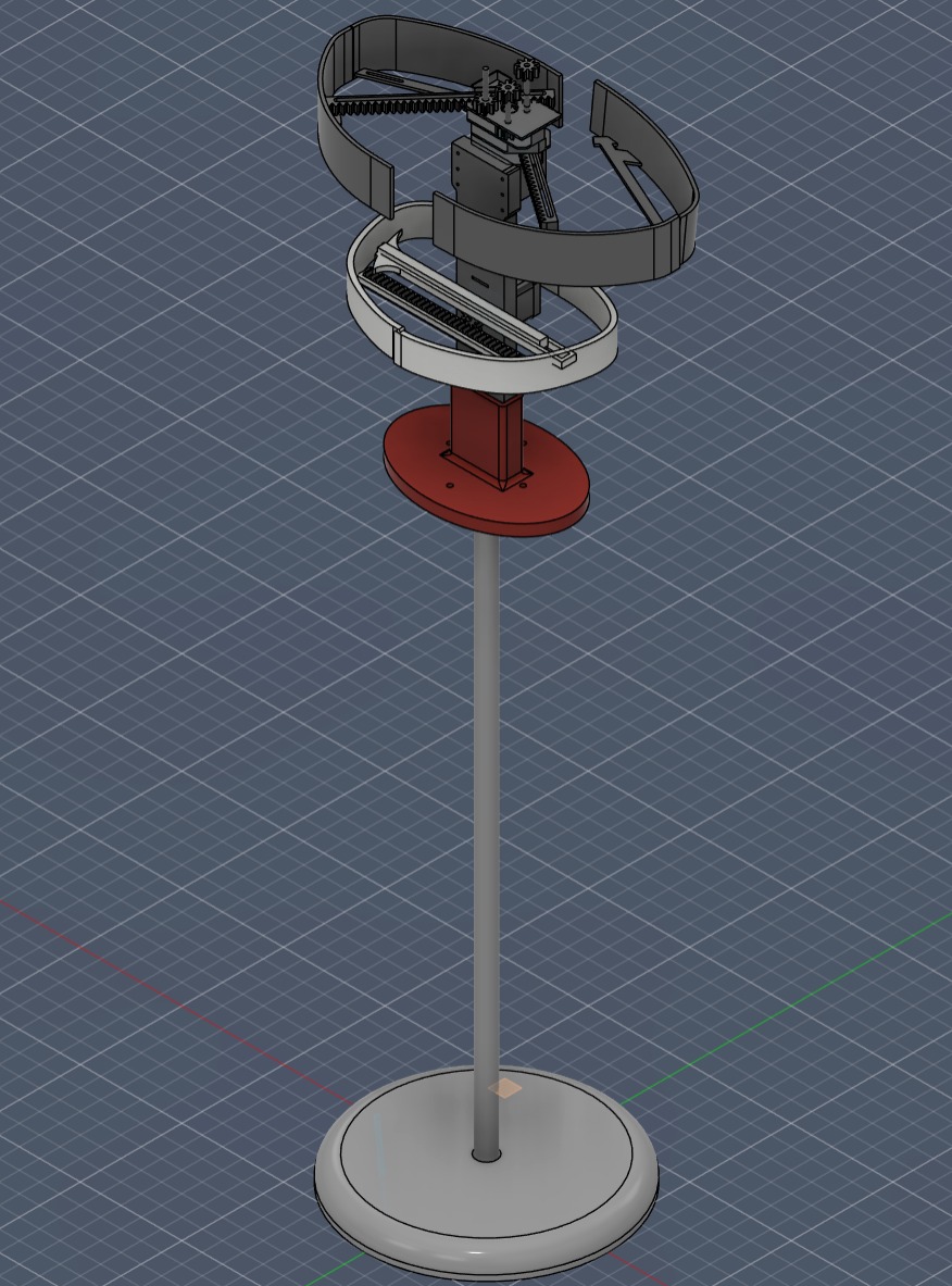
During a final development sprint, I redesigned the mechanism into a Spider Radial Expansion system. This utilizes a multilayered rack and pinion mechanism for much higher reliability. This was the major issue I faced during the design of this project. Below is a progress of what the first bust mechanism was and the final design sketch I developed.
Integration Status
| System Component | Status | Action Required |
|---|---|---|
| Motor Functionality | OK | Proceed |
| Electronic Controls | OK | Proceed |
| Mechanical Movement | ISSUE | Redesign for smoothness |
8.0 Electronic Details
Malak Al-Sharqawi — Electronics LeadThe electrical system uses two motors and supports two operating modes: Free Mode and Preset Mode. In Free Mode, you select an axis and control it using the rotary encoder. In Preset Mode, you can choose between Small, Medium, and Large sizes, and the mannequin adjusts its dimensions accordingly. At startup, the system homes itself by rotating the motors until the limit switches are pressed.
Detailed documentation for the electronic components and their integration can be found on Malak's documentation page.
Electronic Connection Diagram
Building Circuit
Free Mode
Malak started by implementing the free mode, using the CNC shield with push buttons and a rotary encoder.
In the video, you can see the motor being controlled using the push buttons, with limit switches stopping the motor when it reaches its limits. This allows for safe operation and prevents damage to the machine.
Download the code: first_mode_without_oled.rar
Next step: adding the OLED display to enhance the user interface.
Download the code: done_first_mode.zip
Control Panel
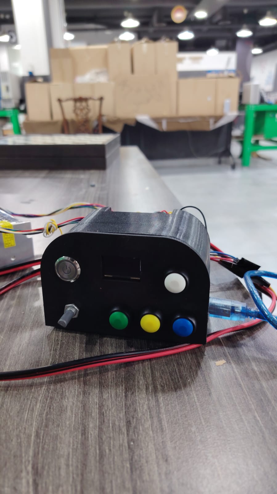
Malak designed a control panel to make user interaction easier. It includes buttons for selecting the mode and axis, a rotary encoder for adjusting dimensions, and an OLED display for feedback.
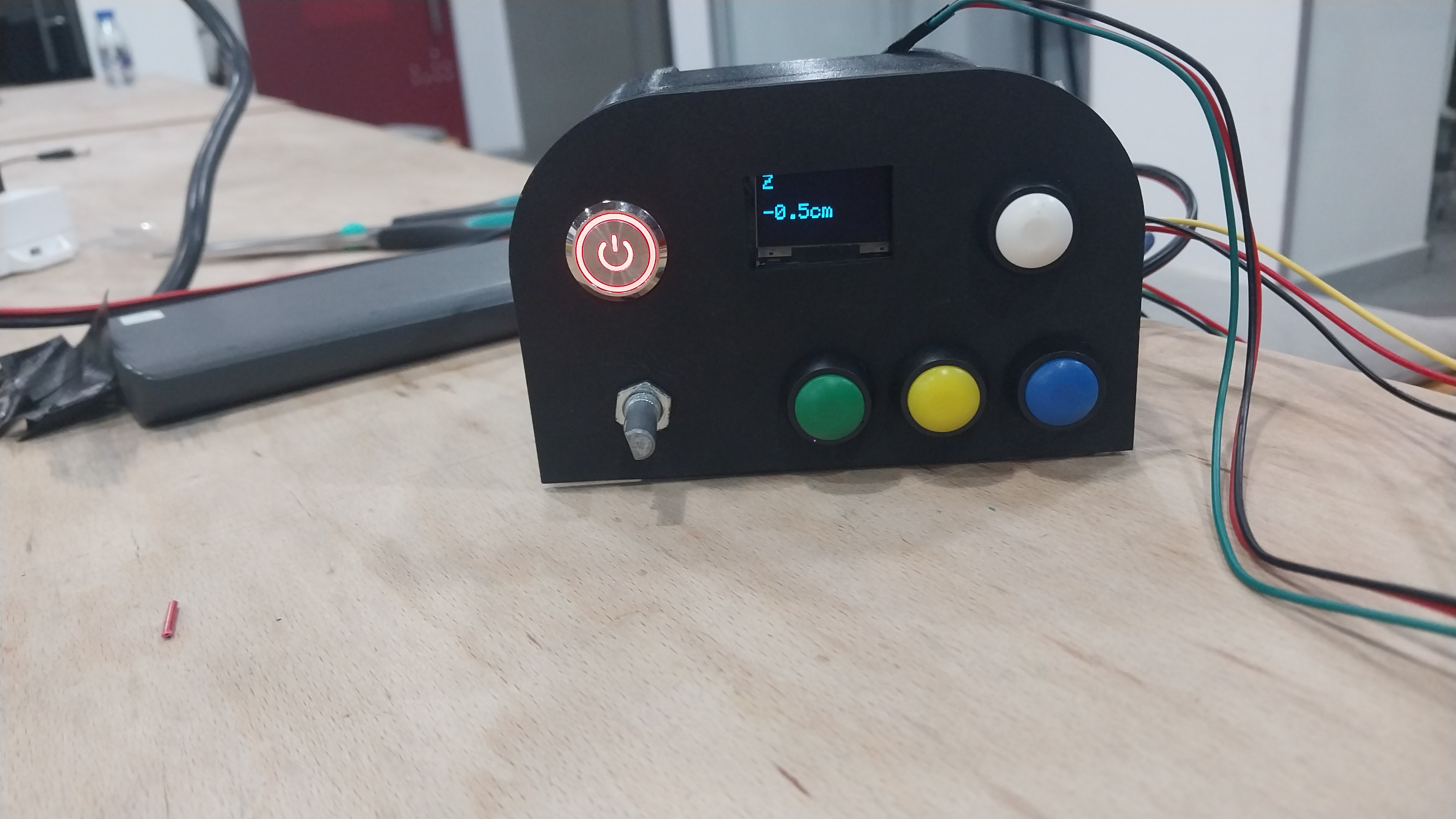
Components
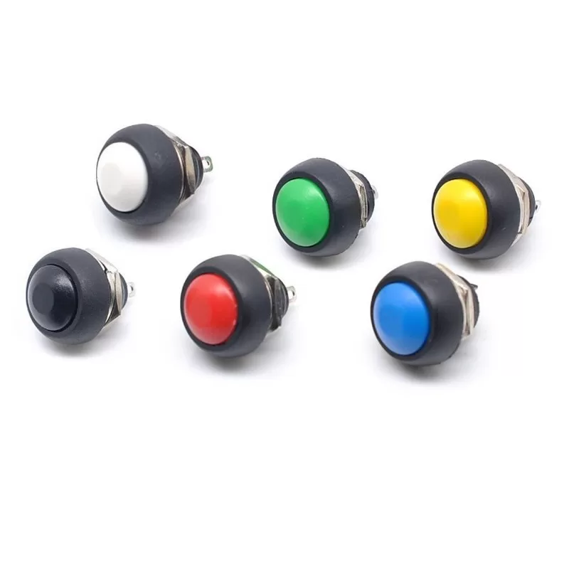
- Push Buttons: used for selecting the mode (free or preset) and for selecting the axis (X, Y, Z). A 2-pin mini switch (1A, 12V): waterproof PBS33B momentary, non-locking push button.
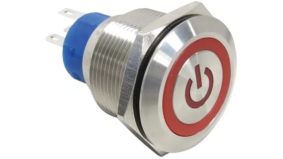
- Power Button: used to turn the machine on and off. A 12V 16mm metal push-button switch with LED momentary reset.
- Rotary Encoder & OLED Display: used for adjusting dimensions and providing real-time feedback.
Design
The control panel was designed in Fusion 360, the front part laser-cut from wood, and the back part 3D-printed to hold the components in place. The design allows easy access to the buttons and display while keeping the wiring organized and secure.
Download the design file: control-panel-design.stl
Soldering
After assembling the control panel, all components were soldered to ensure secure and reliable connections.
Testing the First Mode
After completing the control panel, the first mode was tested to ensure everything was working correctly — verifying that the buttons and rotary encoder functioned as intended.
Add Second Mode & Integrate
After successfully testing the first mode, the second mode (Preset Mode) was added and integrated with the control panel. The second mode provides a preset option for users to quickly select from predefined sizes S, M and L.
Download the code: final.zip
Final Testing
A comprehensive test of the full machine was conducted to ensure all components worked together seamlessly — both Free Mode and Preset Mode verified with correct responses to user input and smooth motor operation.
9.0 Final Results
The transition to the radial expansion mechanism allowed for synchronized, smooth adjustments across all body segments. The prototype successfully responds to digital inputs to match specific anatomical measurements. However there is further room to improve the assembly and model for the central spider radial expansion mechanism by introducing guides, sliders, and a more efficient design for the gearbox itself — it was nonetheless a successful proof of concept to produce and manufacture the components and test them outside of the full assembly.
The waist mechanism was fully functional and achieved its target to prove it can be integrated in future iterations of digital mannequins.
10.0 Possible Improvements
If we continue developing this project, the next improvements would focus on reliability, user experience, and mechanical refinement:
- Add a stronger enclosure and cleaner cable management to protect the electronics.
- Improve the radial mechanism with better bearings or low-friction guides for smoother motion.
- Add preset memory storage so the mannequin can save custom sizes beyond S, M, and L.
- Replace the current display flow with a more polished menu and clearer on-screen feedback.
- Introduce dedicated slider guides and a more efficient gearbox design for the spider radial expansion mechanism.
- Expand to the Neck/Shoulders measurement axis (currently scoped but not yet implemented).