Week 9: Input Devices
This week focuses on understanding input sensors, interpreting digital vs. analog signals, and utilizing test equipment to observe real-time sensor waveforms communicating with an MCU.
Understanding Input Signal Workflows
When working with microcontrollers, input hardware sends data across two core electrical types:
- Digital Signals (Obstacle Sensor): Binary transitions that instantly snap between a state of HIGH (VCC) and LOW (0V).
- Analog Signals (Potentiometer): Continuous variable voltage ranging from 0V up to VCC, decoded by the MCU's Analog-to-Digital Converter (ADC).
Oscilloscope Setup (GW Instek GDS-1152A-U)
To read these signals reliably without clipping or losing resolution, the hardware scope settings must match the probe characteristics.
1. Reference Grounding:
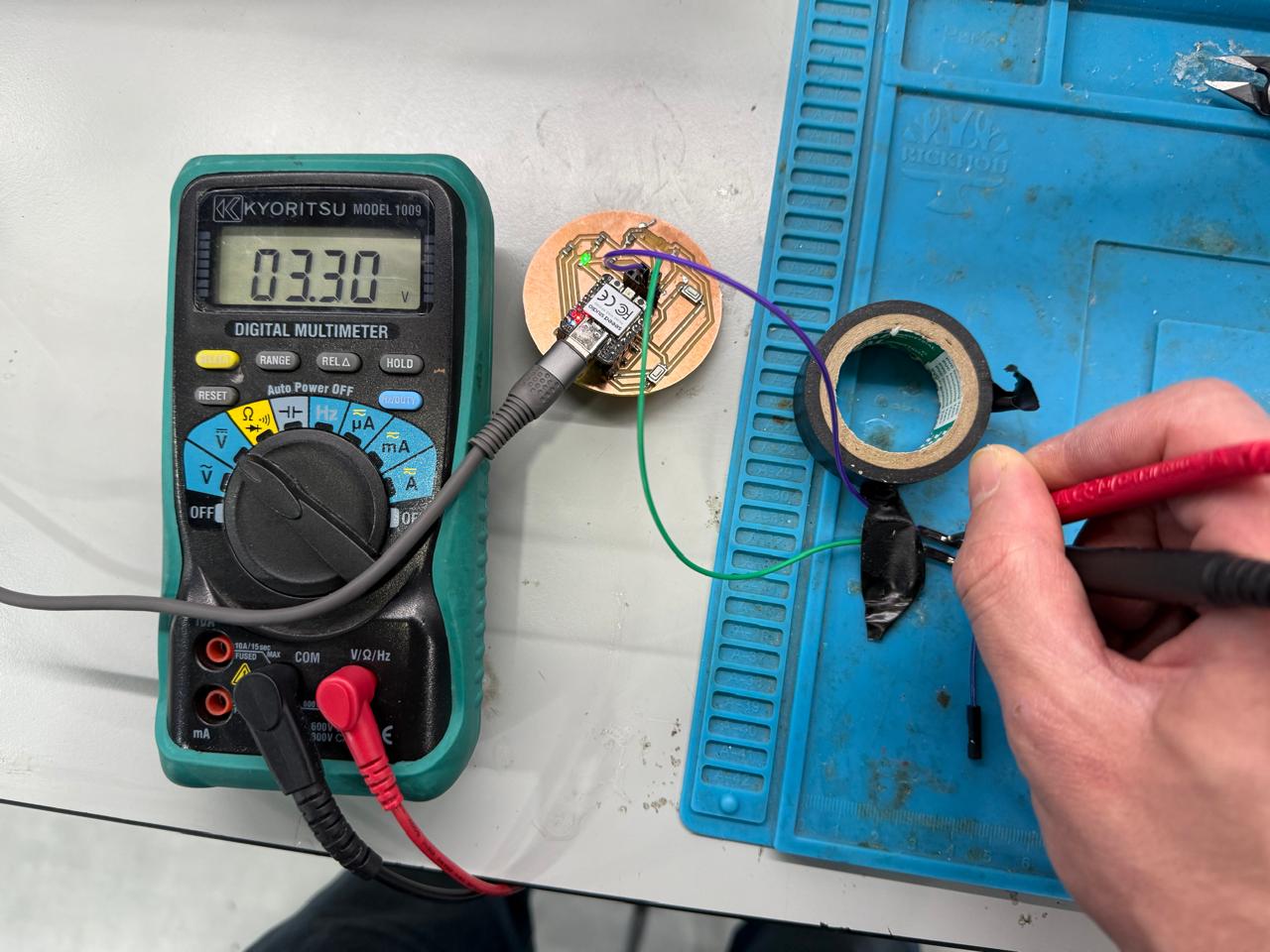
Connect the probe's black alligator clip firmly to a common GND bus shared by the microcontroller and sensors. Failing to establish a mutual ground reference injects destructive floating environmental noise into your traces.
2. Probe Attenuation Link:
Match the physical switch toggle on your probe handle (1X or 10X) with the internal system software scale. Click the CH1 Menu button on the panel face and modify the Probe attenuation multiplier variable to match the toggle choice.
Probing the Obstacle Sensor (Digital)
Digital interaction takes place in millisecond windows. If your scope is mistakenly adjusted to microseconds or low millivolt vertical windows, the signal waveform will look flat or display ambient room noise.
Physical Connection:
GDS-1152A-U Adjustments:
- Coupling: Set to DC. (Avoid AC coupling, as it filters out the flat DC baseline transitions you need to monitor).
- VOLTS/DIV: Set to 1V or 2V per division so a 3.3V/5V shift is easily viewable inside the grid bounds.
- TIME/DIV: Scale out to 50ms or 100ms to view human interaction timeframes.
- Trigger Menu: Type: Edge | Source: CH1 | Slope: Falling | Mode: Auto.
Attach the CH1 probe tip clip to the digital output pin (OUT/DO) of the infrared obstacle module.
Modify variables using the control knobs to match the configuration rules below:

Troubleshooting Signal Anomalies
If your scope readouts produce a dense, high-frequency fuzzy yellow band rather than a solid signal line, use the following validation routine:
| Observed Symptom | Root Electrical Cause | Corrective Action Required |
|---|---|---|
| Dense 50Hz/60Hz fuzzy wave blocks | AC coupling active or missing common reference Ground line | Switch Channel Coupling from AC to DC. Re-verify the black alligator ground clip link. |
| Flat line with minor static near 0V | Vertical scale resolution is too sensitive (e.g., 5mV/Div) | Turn VOLTS/DIV counter-clockwise to scale up to 1V or 2V per division block. |
| Signal jumps out of display limits | Incorrect attenuation settings | Validate that the 1X/10X hardware switch on the physical probe body perfectly matches the channel software variable. |
Conclusion
Accurately acquiring input sensor signals requires matching the oscilloscope's time domains, voltage scales, and reference grounding to the real-world behaviors of your physical components. Verifying inputs with a diagnostic hardware trace before writing or testing microcontroller code ensures clean processing lines and prevents debugging software for failures caused by hidden hardware noise.