Week 5: 3D Scanning and Printing
This week we moved from 2D cutting into the world of additive manufacturing. Our group worked with the Ultimaker S5 FDM printer to systematically explore the range of 3D printers at our lab. We were introduced to design-rule testing, and how to start, operate, and maintain 3D printers primarily focused on the Ultimaker S5 in our lab. The design rule testing checks crucial baseline limitations: overhangs, bridging, and dimensional accuracy.
Group Assignment Requirements
- Test the design rules for your 3D printer(s).
- Document your work on the group work page and reflect on your individual page what you learned about the characteristics of your printer(s).
Machine Overview & Hardware Setup
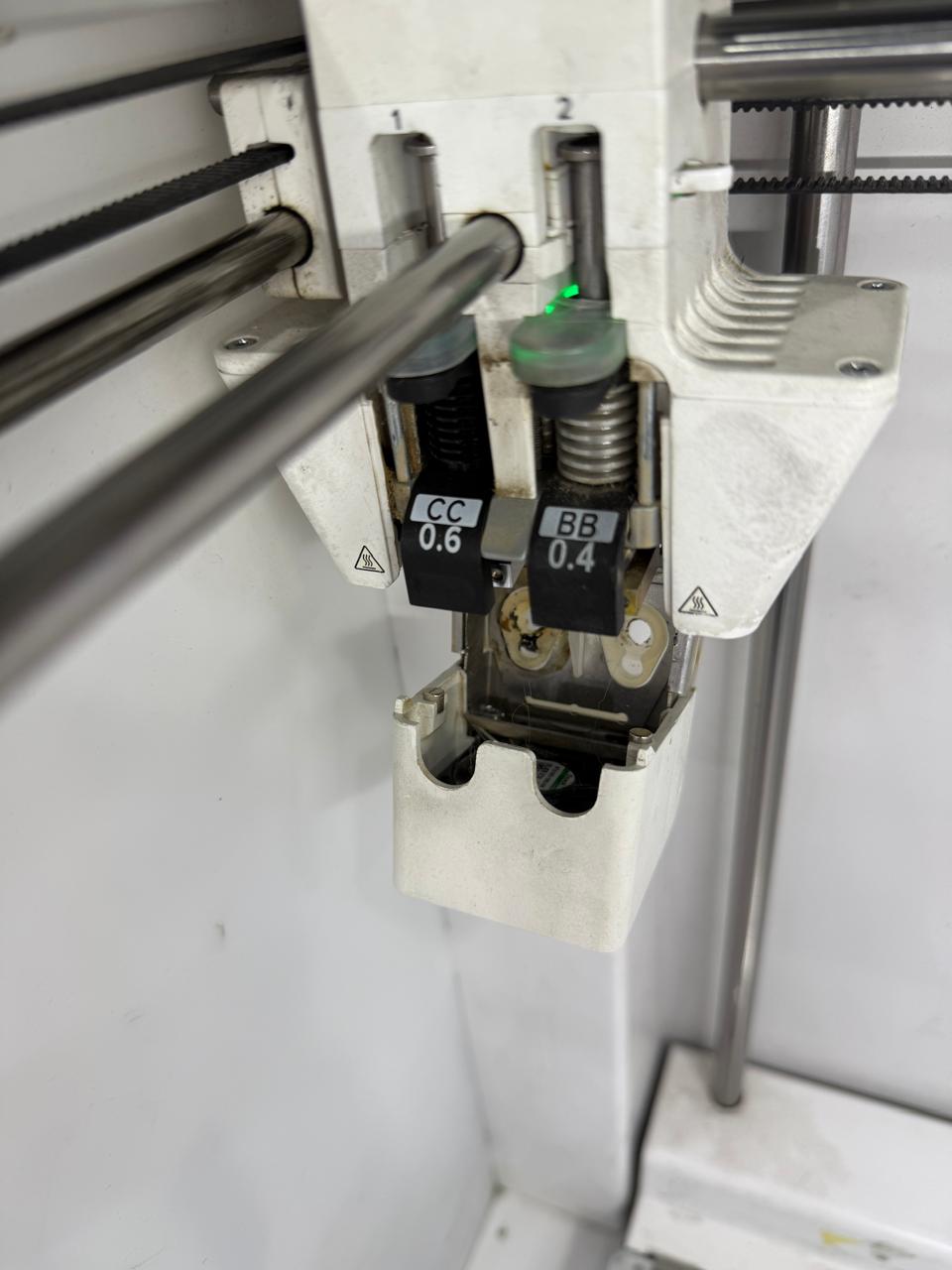
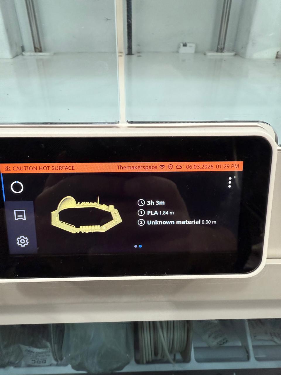
The Ultimaker S5 is a professional-grade dual-extrusion FDM printer with a generously sized build volume. Its enclosed frame and heated bed make it well-suited for a broad range of filament materials beyond basic PLA — including nylon, PETG, and flexible TPU. The dual print-core system lets you load a support material (such as PVA) alongside the primary filament. During our hardware preparation, we verified our active print cores directly inside the print head assembly.
| Parameter | Value | Notes |
|---|---|---|
| Machine | Ultimaker S5 | Professional dual-extrusion FDM desktop printer |
| Build Volume (L × W × H) | 330 × 240 × 300 mm | One of the largest desktop FDM envelopes available |
| Min. Layer Height | 0.06 mm | Achievable with 0.4 mm nozzle at reduced speed |
| Max Volumetric Flow | 40 mm³/s | Varies by nozzle diameter and material |
| Filament Diameter | 2.85 mm | Bowden-fed; not compatible with 1.75 mm spools |
| Max Nozzle Temp. | 280 °C | Supports engineering-grade filaments |
| Heated Bed Max Temp. | 140 °C | Glass bed with adhesive BuildTak surface |
| Print Technology | FDM (Fused Deposition Modeling) | Thermoplastic filament melted through heated nozzle |
| Test Material | PLA — 2.85 mm | Standard material; good detail; no enclosure required |
| Slicer Used | Ultimaker Cura (latest stable) | Native integration with S5 printer profiles |
Safety Practices
Before operating the Ultimaker S5, every group member reviewed the lab's safety guidelines for FDM printing. While 3D printers are generally lower-risk than machine tools, there are several real hazards that deserve attention:
- Hot surfaces: The nozzle reaches up to 200 °C for PLA and the bed up to 60 °C. Never touch either during or immediately after a print — use tools to remove parts from the bed.
- Fumes and particulates: Melting thermoplastics releases ultrafine particles. The printer was operated with the lab ventilation running; the room door stayed open throughout.
- Filament loading: When changing filaments, wait for the printer's guided unload sequence — pulling cold filament forcefully can jam the Bowden tube.
- Unattended prints: Long prints were monitored periodically. A print that detaches mid-job can cause filament to tangle or the nozzle to crash into the build plate.
- Bed removal: A thin palette knife was used to pry parts off after the bed cooled, reducing the risk of cracking the glass surface or slipping with a sharp blade.
- Electrical: The machine was plugged into a surge-protected outlet. No cable extensions were used near the printer enclosure.
Slicing Profiling & Filament Comparison Tests
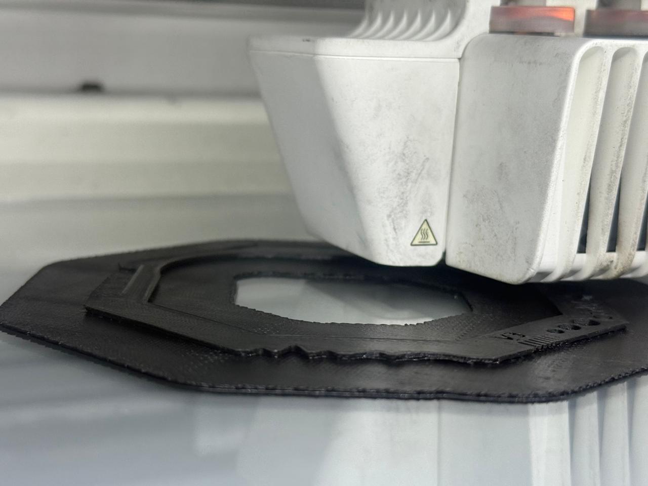
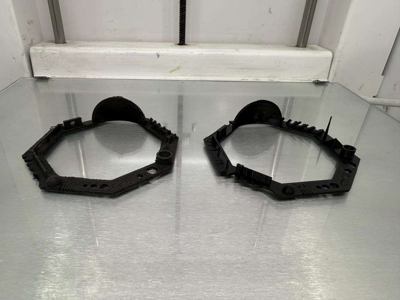
All test geometry was sliced in Ultimaker Cura. To understand our operating parameters fully, we contrasted two distinct setups: an uncalibrated profile running a rough profile settings test versus a properly adjusted generic PLA settings configuration. The side-by-side differences clearly showcase how profile accuracy dictates part success.
Material: PLA | Nozzle: 0.4 mm | Layer height: 0.2 mm | Infill: 20% grid | Print speed: 50 mm/s | Supports: None | Adhesion: Brim (8 mm) | Cooling: 100% fan from layer 3
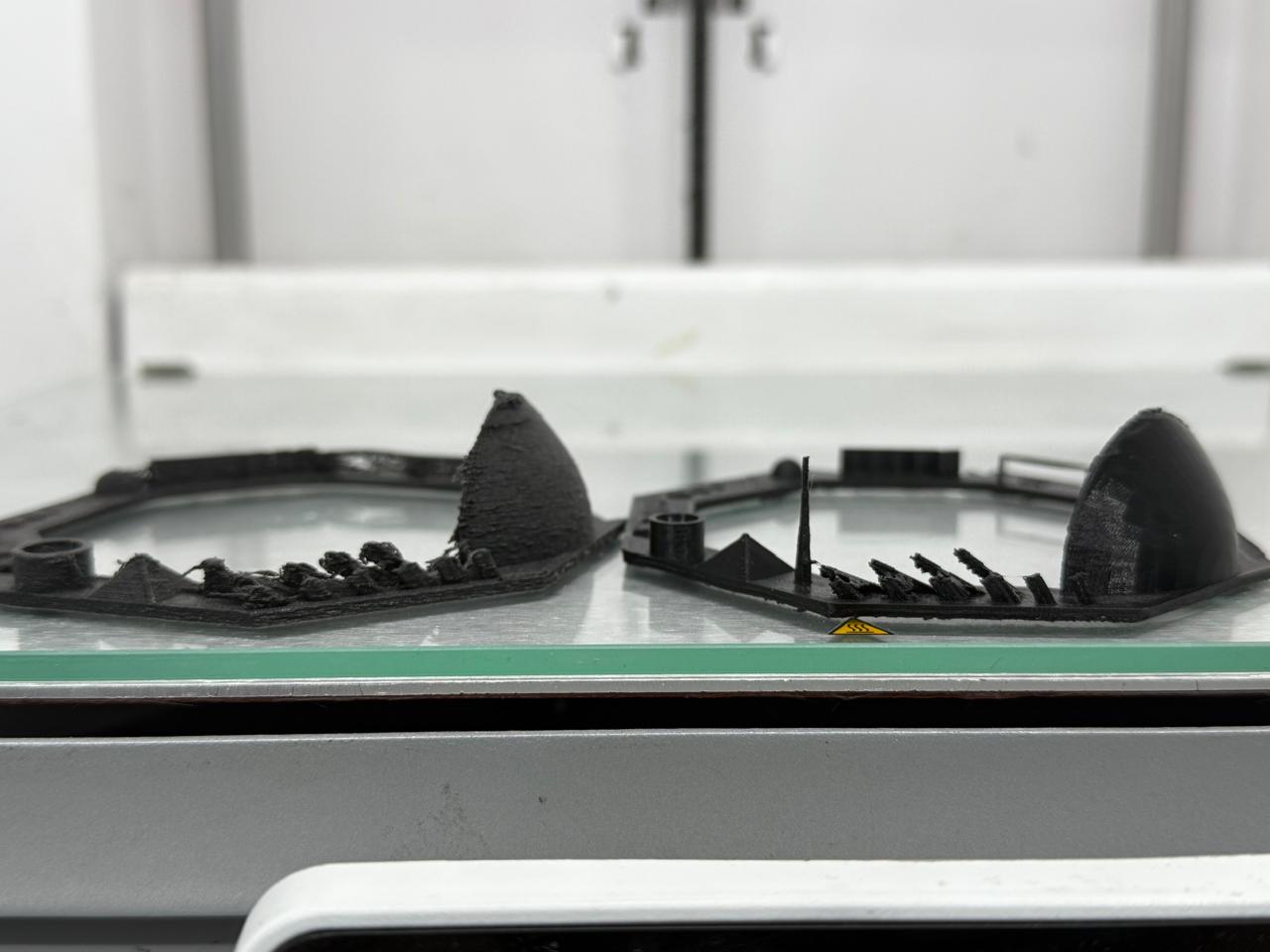
Design Rule Test Model
We used the Thingiverse "Test Your 3D Printer" model by ctrlV (thing:1363023). This well-established test geometry packs several independent capability checks into a single compact print, evaluating multiple parameters simultaneously.
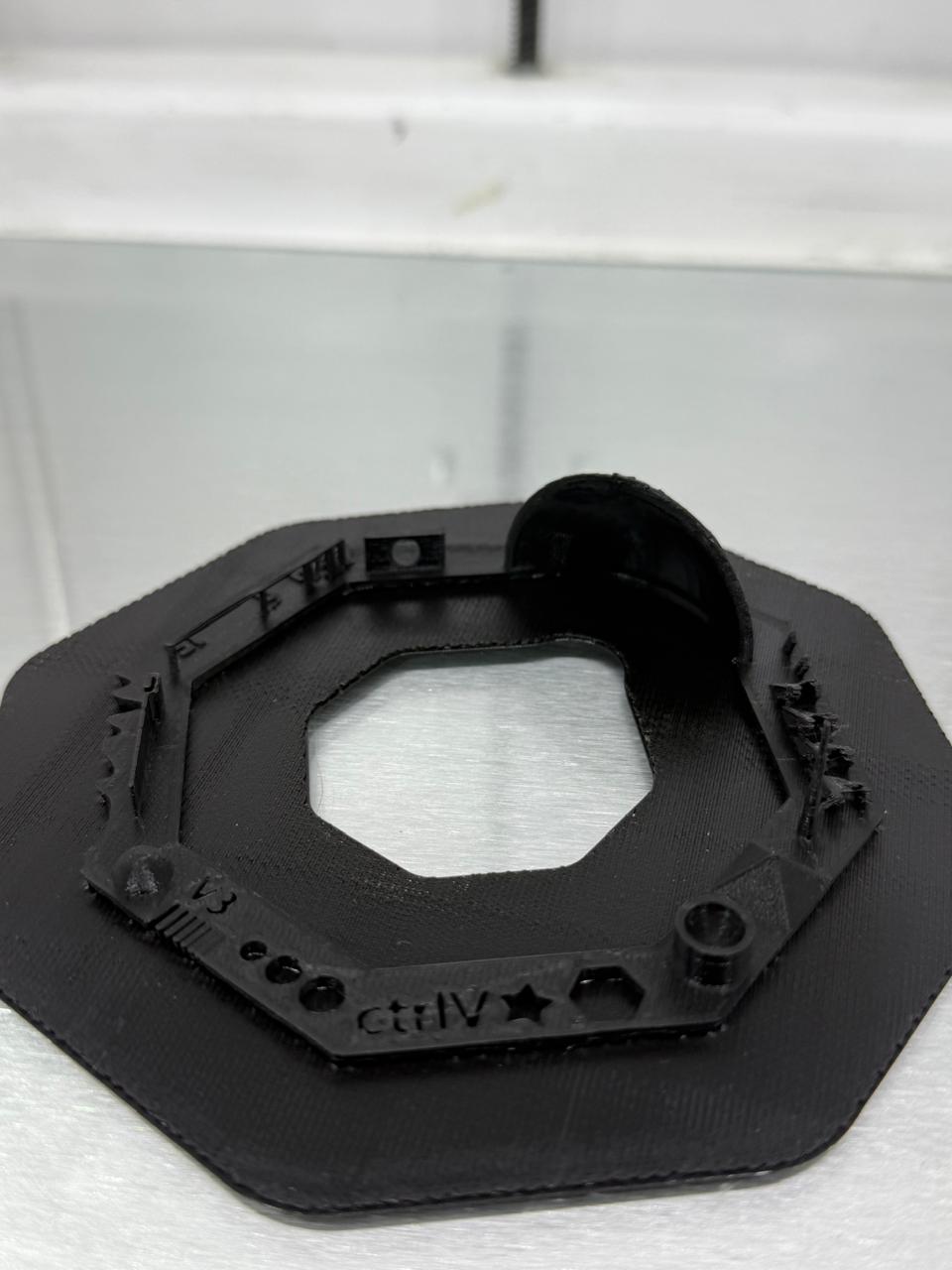
Test Results Analysis
Result 1 — Overhang & Curved Surface Performance
Overhangs remain one of the most limiting factors in FDM printing. Without support material, the printer must deposit filament partially into open air. We looked underneath the stepping geometries and internal curved arches to trace the exact threshold of performance breakdown.
- Clean layer lines visible
- No drooping or curling
- Smooth under-surface
- Slight surface roughness underneath
- Minor filament sag visible on close inspection
- Top surface remains clean
- Visible filament drooping
- Stringy under-surface texture
- Layer adhesion to prior layer weak
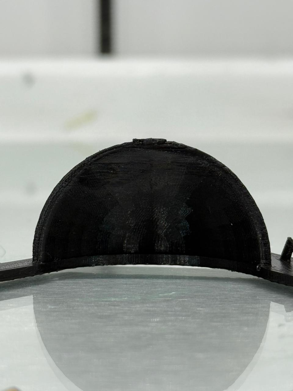
Takeaway: Design features with overhangs up to 45° can be printed confidently without supports. The 50° zone is usable for non-cosmetic geometry. Anything steeper should either be reoriented on the build plate or have support material enabled in Cura.
Result 2 — Bridge Span Performance
Bridging measures how far the printer can span a horizontal gap between two walls before filament begins to sag significantly. The test model includes progressively wider gaps. Each was inspected visually and tactilely handled to verify actual material deflection limits.
| Bridge Span | Under-surface Quality | Sag Visible? | Verdict |
|---|---|---|---|
| 5 mm | Perfectly flat | None | Excellent |
| 10 mm | Flat with faint ripple | Barely perceptible | Excellent |
| 15 mm | Slight mid-span roughness | Minimal | Good |
| 18 mm | Noticeable texture underside | Yes — ~0.5 mm | Marginal |
| 22 mm | Visible stringing and sag | Yes — ~1.5 mm | Needs supports |
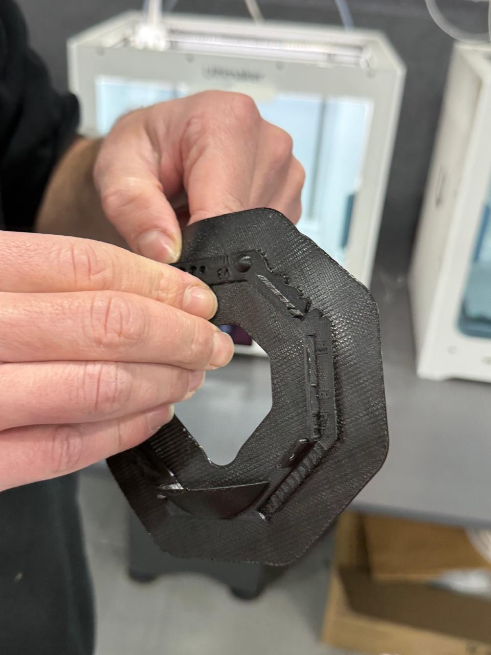
Takeaway: The Ultimaker S5 handles unsupported bridges up to about 15 mm reliably. At 18 mm the result is still acceptable for internal geometry, but anything beyond that should be supported or re-designed with an arch profile to distribute the load.
Result 3 — Fine Detail Reproduction & Dimensional Accuracy
The test model includes raised lettering, thin walls, and a calibration column with a nominal outer diameter of 20 mm. After printing, we measured the column with a digital caliper in two perpendicular orientations and compared the readings to the CAD dimension.
Fine detail: Raised lettering 1 mm tall was clearly legible. The thinnest test wall (0.4 mm, equal to one nozzle width) printed as a single-extrusion pass with no gaps, though it required careful handling off the bed. Walls at 0.8 mm and above were robust and fully fused.
Design Rules Summary Table
| Capability | Tested Range | Safe Design Limit | Notes |
|---|---|---|---|
| Overhang (no supports) | 30° – 70° | ≤ 45° | 50° borderline; 60°+ requires supports |
| Bridge span (no supports) | 5 – 22 mm | ≤ 15 mm | 18 mm marginal; beyond that use supports |
| Minimum wall thickness | 0.4 – 2.0 mm | ≥ 0.8 mm | 0.4 mm possible but fragile |
| Dimensional accuracy (XY) | 20 mm reference | ±0.15 mm typical | Uniform −0.1 mm offset; tunable via flow rate |
| Layer height used | 0.2 mm | 0.15 – 0.25 mm | 0.2 mm balances speed and detail well |
| Embossed text readability | ≥ 1 mm feature height | ≥ 1 mm | Sub-1 mm text loses legibility at 0.2 mm layers |
Reflection & Key Takeaways
- The 45° rule is real — and easy to design around. We initially thought overhangs up to 60° might print cleanly given the S5's reputation as a precision machine. In practice, gravity wins above 50°. Reorienting a model so that overhangs fall within the safe zone is almost always a better solution than adding support structures, which leave marks on the surface.
- Bridging is better than expected for short spans. The S5's high cooling fan speed (100% from layer 3) and relatively slow bridge print speed in Cura's default profile solidify the filament quickly enough to bridge 15 mm cleanly. This is useful for printing cable channels, slots, and window cutouts without supports.
- Dimensional accuracy requires a flow-rate check. A consistent −0.1 mm offset across both axes is not a geometry or axis problem — it is a calibration issue with extrusion volume. A quick flow-rate calibration print would be worth running before any precision-fit part. For most structural prints the current accuracy is fine, but for parts that mate with off-the-shelf hardware (screws, bearings, threaded inserts), the offset matters.
- Think in layers — literally. Small features like text or pins smaller than one nozzle diameter are not reliably reproducible. When designing for this machine, keeping minimum features at 0.8 mm (two extrusion widths) ensures structural integrity and clean edges. When in doubt, model it slightly oversized and sand to fit.