Week 7: Computer-Controlled Machining
This week shifts scale from desktop PCB milling to large-format subtractive fabrication. Working with the ShopBot Gantry CNC and 18 mm plywood, our group characterized the machine's real-world performance across three core areas: spindle speed, dimensional accuracy, and part-to-part fit tolerance. The goal was to build an evidence-based reference that anyone in the lab can use before committing to a full production cut.
Group Assignment Requirements
- Complete your lab's safety training.
- Test runout, alignment, fixturing, speeds, feeds, materials and toolpaths for your machine.
- Document your work to the group work page and reflect on your individual page what you learned.
Machine Overview & Toolpath Setup
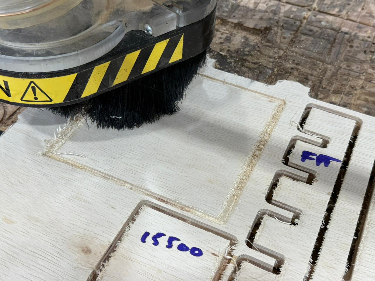
The ShopBot Gantry is a large-format CNC milling system whose spindle travels on a rigid overhead bridge (gantry) spanning the full working bed. Unlike desktop machines where the bed moves, here the spindle assembly travels in X and Y while the Z-axis drives the collet up and down into the material. This architecture keeps the workpiece stationary — critical when cutting heavy sheet goods like 18 mm plywood.
| Parameter | Value | Notes |
|---|---|---|
| Machine | ShopBot Gantry (PRSalpha series) | Large-format, lab floor-mounted |
| Max Spindle Speed | 18,000 RPM | Variable via ShopBot controller |
| Standard Feed Rate | 15,000 mm/min (15 m/min) | Used for wood / MDF production cuts |
| Rapid / Transit Feed | 40 m/min | Movement above the material only |
| Test Material | 18 mm Plywood | Standard structural sheet; 1220 × 2440 mm |
| Bit Used | 6 mm flat / square end mill | Upcut spiral, 2 flutes |
| Fixturing Method | Screw-down to sacrificial spoilboard | Perimeter screws at 150 mm intervals |
Safety Training & Stock Preparation
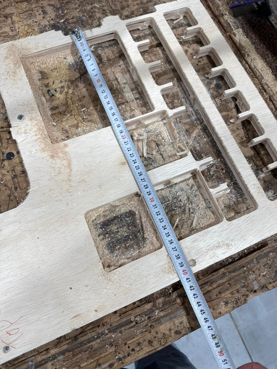
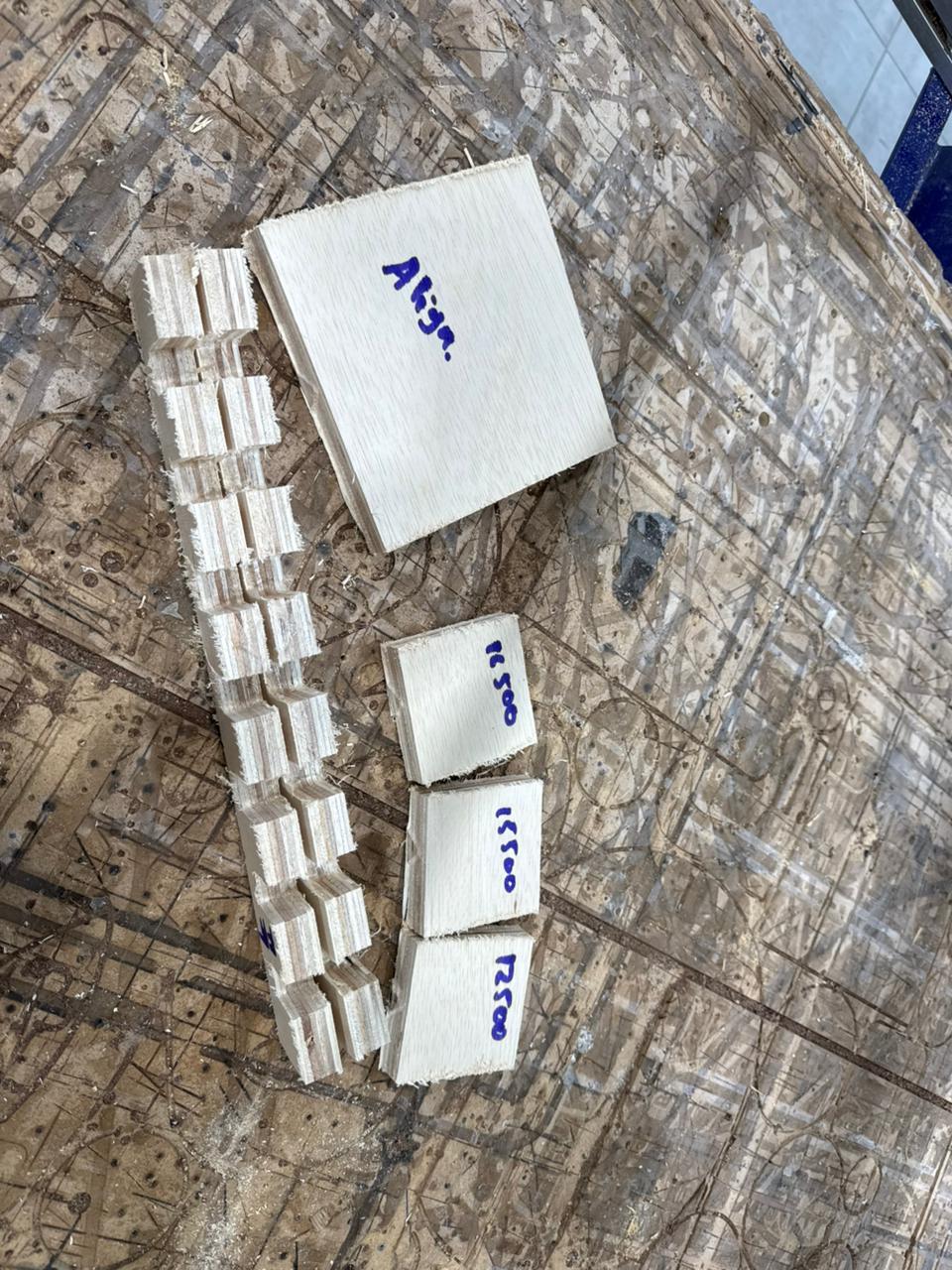
Before any machine time was granted, all group members completed the lab's mandatory ShopBot safety induction. We prepared a standard 1220 × 2440 mm sheet of 18 mm plywood. Stock must be fully secured; a loose sheet can move slightly under high load forces, leading to geometric skewing or ruined parts. We carefully aligned the plywood board flat to the spoilboard bed and fastened the margins securely.
- No loose clothing or jewelry near the spindle area at any time.
- Hearing and eye protection must be worn whenever the spindle is running.
- Dust extraction must be connected and verified before starting a job — MDF and plywood dust are respiratory hazards.
- Never reach over the bed while the gantry is in motion; the machine does not detect obstructions.
- Emergency stop (E-stop) location confirmed by every operator before powering on.
- Bit changes only performed with the spindle fully stopped and the machine in a parked, zero-power state.
- Stock must be fully secured (screwed or clamped) before starting — a loose sheet becomes a projectile at high feed rates.
Test 1 — Spindle Speed Characterization
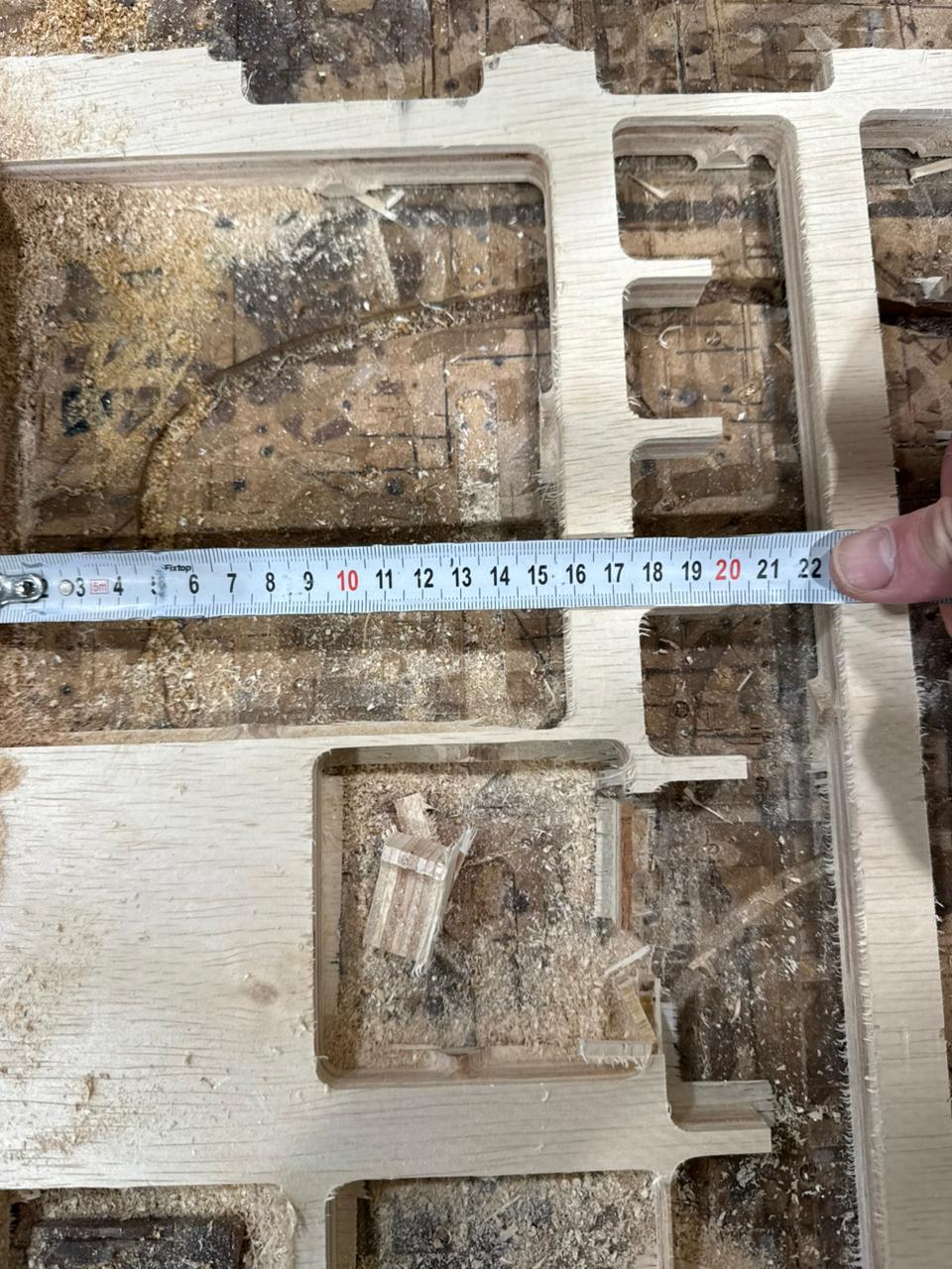
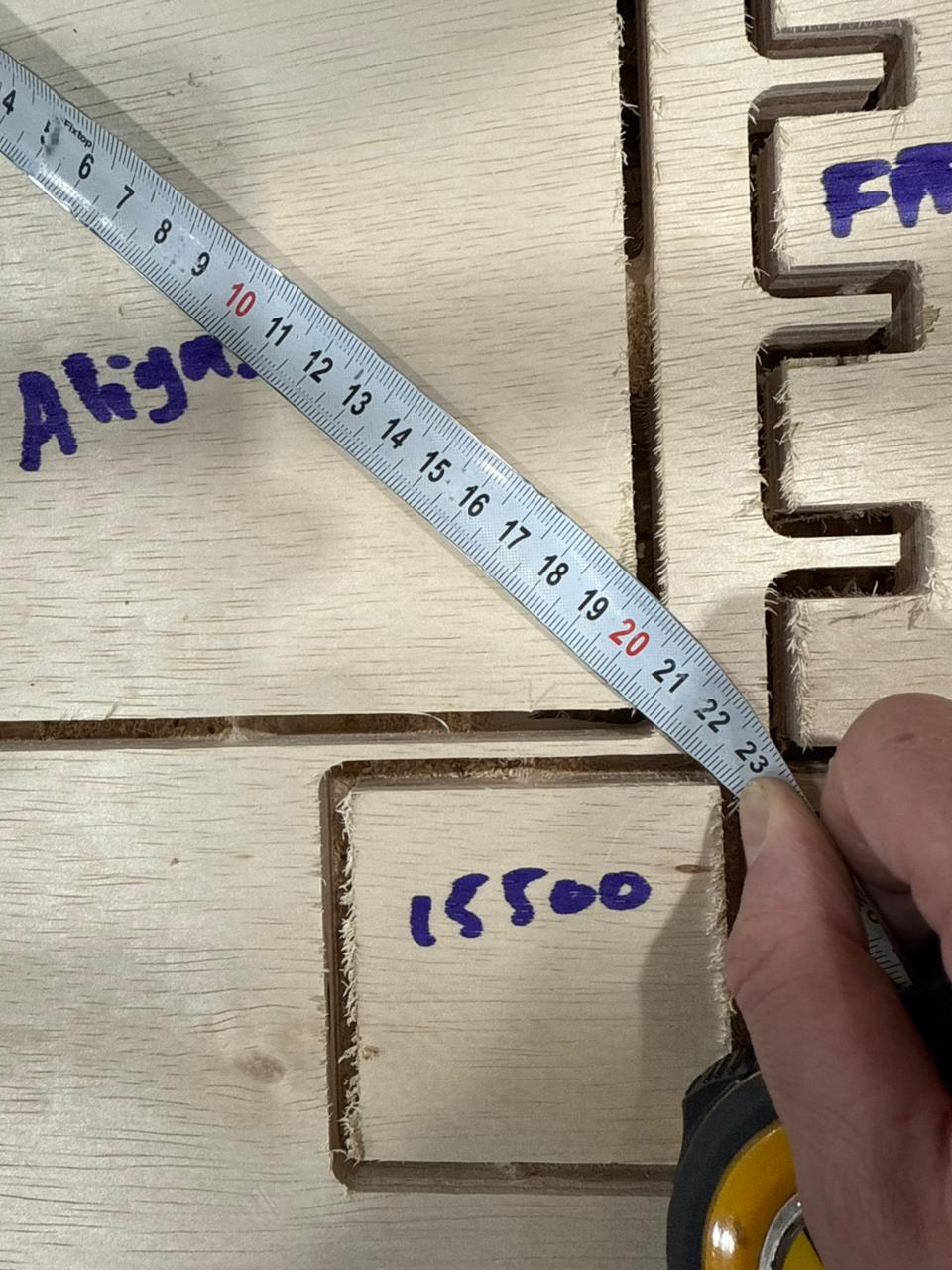
To understand how spindle RPM affects cut quality on 18 mm plywood, we cut three identical 50 × 50 mm square pockets at three different spindle speeds while keeping feed rate, pass depth, and toolpath identical. Each square was then examined visually and by hand for surface finish, edge tearout, and burning.
Feed rate: 15,000 mm/min | Pass depth: 6 mm | Tool: 6 mm 2-flute upcut end mill | Material: 18 mm plywood
- Clean, smooth side walls
- Minimal tearout on grain exit
- No burning observed
- Fine dust; good chip evacuation
- Smooth walls, slightly rougher than A
- Slight fuzz on top ply layer
- No burning
- Good chip size; adequate evacuation
- Noticeable grain tearout on edges
- Rougher pocket floor
- Larger chips; some re-cutting
- Slight tool chatter audible
| RPM | Surface Finish | Edge Tearout | Burning | Chip Evacuation | Verdict |
|---|---|---|---|---|---|
| 16,500 | Smooth | Minimal | None | Excellent | Recommended |
| 15,500 | Good | Slight fuzz | None | Good | Acceptable |
| 12,500 | Rough | Noticeable | None | Adequate | Not Recommended |
Takeaway: Design features with profiles up to 16,500 RPM print and cut with maximum definition. Lower spindle speeds around 12,500 RPM degrade the edge cleanly due to chip loading variations, inducing tool chatter across alternating grain plies.
Test 2 — Alignment & Squareness Test
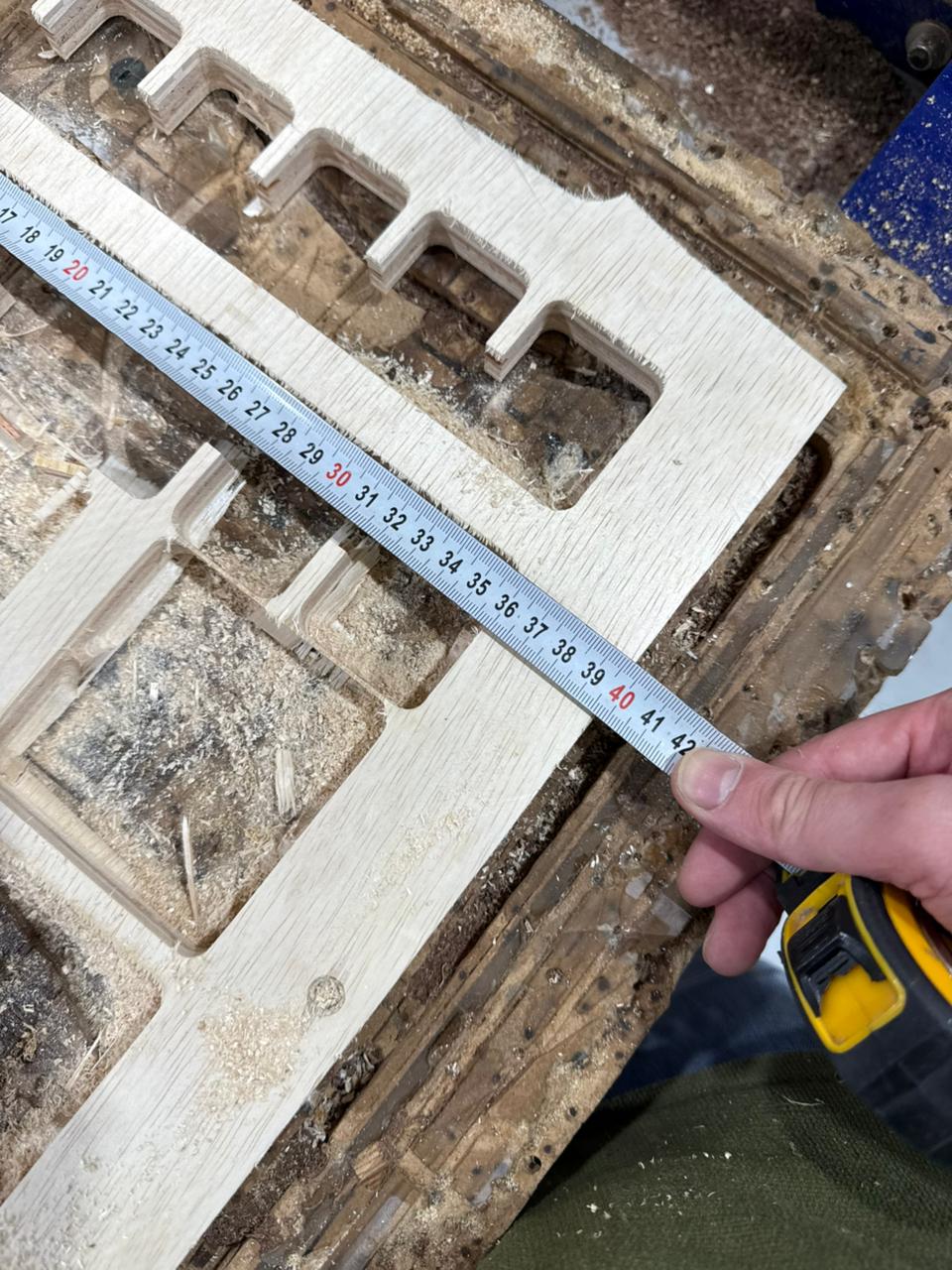
A fundamental check for any CNC machine is whether the axes are truly perpendicular to each other and whether the bed is level relative to the spindle travel plane. We cut a 150 × 150 mm square profile from the 18 mm plywood and then measured both diagonals with a steel rule. On a perfectly square part, the two diagonals must be equal — any difference directly reveals angular error in the machine's X/Y axis calibration.
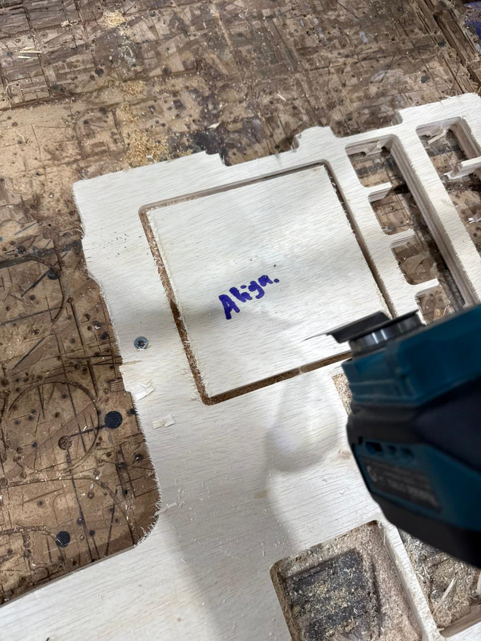
Interpretation: Equal diagonals confirm that the ShopBot's X and Y axes are perpendicular and that there is no measurable racking or skew in the gantry at the time of testing. This also validates that the material was held flat against the spoilboard — a warped or improperly screwed sheet would produce an uneven pocket floor and dimensional shift.
Test 3 — Fit & Tolerance Test
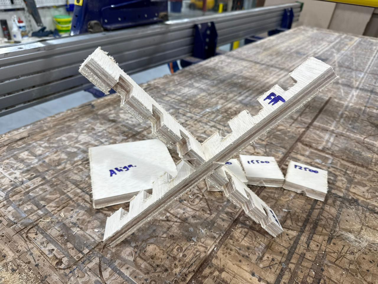
To determine usable tolerances for press-fit joinery (e.g., tabs and slots in flat-pack furniture), we designed a tolerance test set. A series of rectangular male tabs was cut at nominal width, while a matching row of female slots was cut at incrementally increasing clearances. The test reveals at which offset the two parts transition from too tight (requires mallet) through press-fit (hand pressure) to loose (drops in freely).
Tab nominal width: 18 mm (matching material thickness) | Slot offsets tested: −0.2 mm, −0.1 mm, 0.0 mm, +0.1 mm, +0.2 mm, +0.3 mm, +0.4 mm | All parts cut from the same 18 mm plywood sheet at 16,500 RPM.
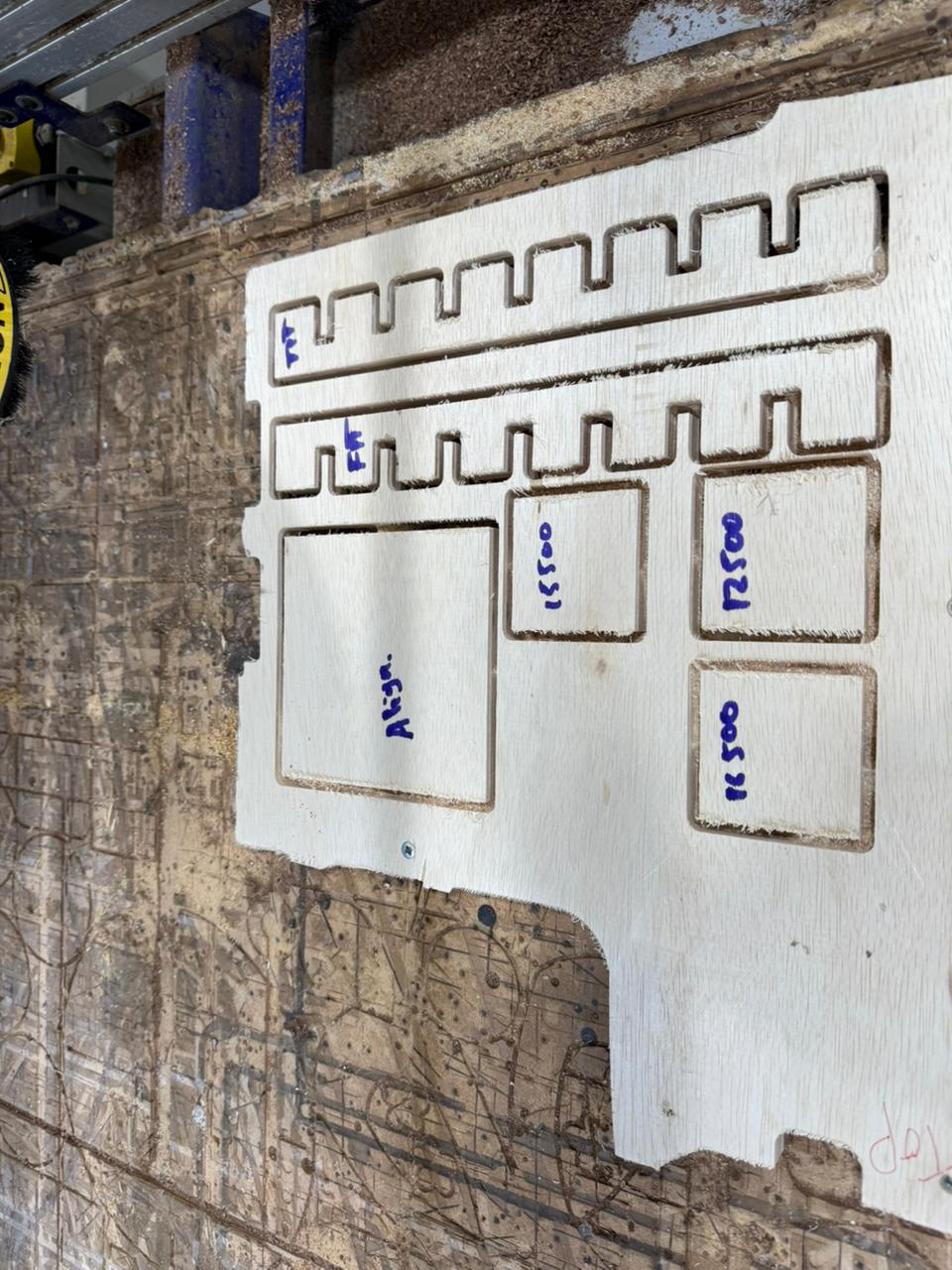
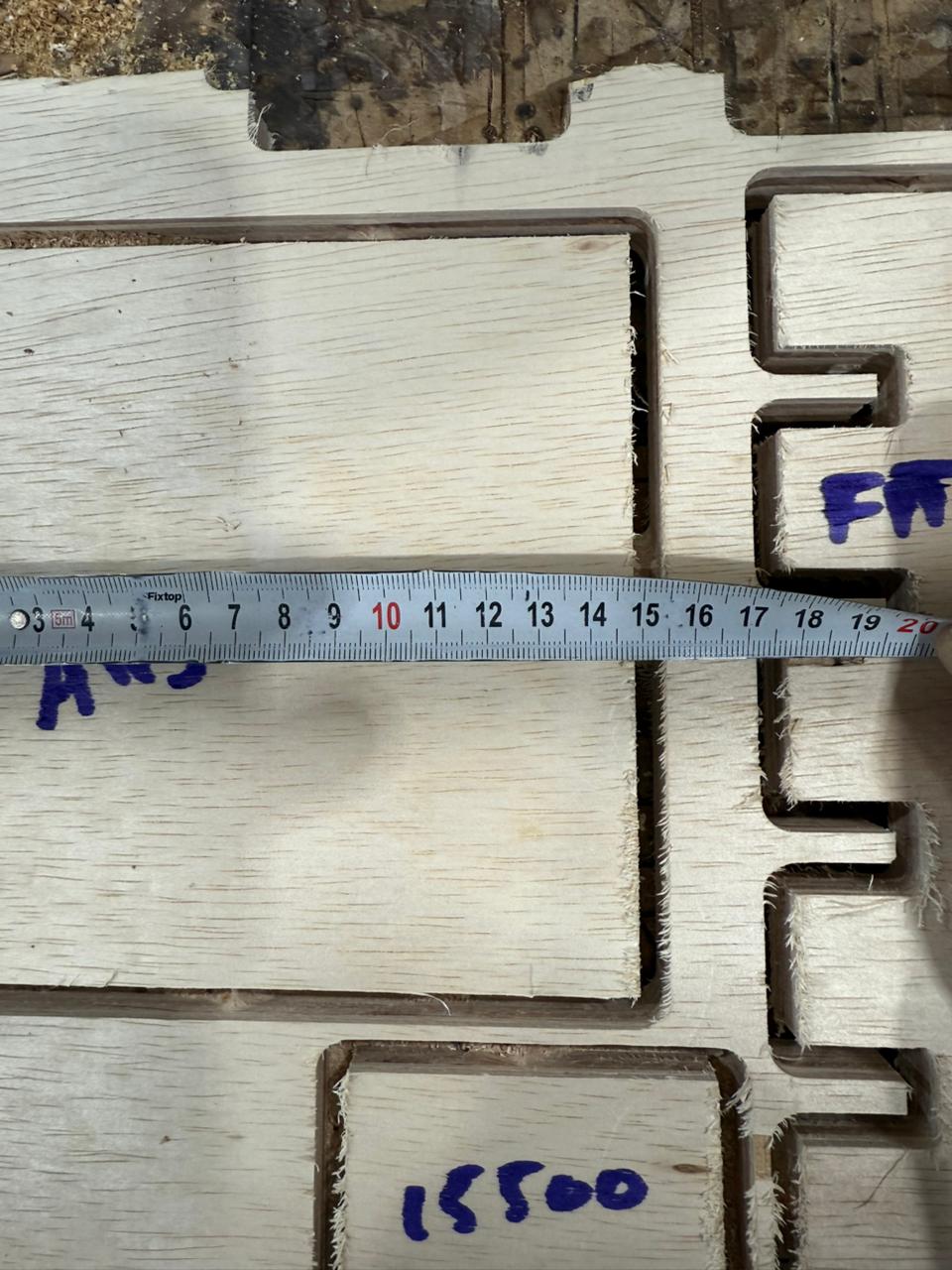
| Slot Offset | Slot Width (mm) | Fit Result | Assembly Method | Recommended Use |
|---|---|---|---|---|
| −0.2 mm | 17.8 | Impossible / binding | Would not assemble | — |
| −0.1 mm | 17.9 | Very tight | Mallet required | Permanent structural joints |
| 0.0 mm | 18.0 | Press-fit ✓ | Firm hand pressure | Furniture / flat-pack joints |
| +0.1 mm | 18.1 | Press-fit ✓ | Easy hand pressure | Preferred for repeatable assembly |
| +0.2 mm | 18.2 | Snug / loose | Slides in by hand | Hinged / removable panels |
| +0.3 mm | 18.3 | Loose | Drops in freely | Test fits / dry assembly only |
| +0.4 mm | 18.4 | Very loose / gap visible | No resistance | — |
Key finding: With this machine, end mill, and material combination, an offset of 0.0 mm to +0.1 mm on the slot dimension produces the most reliable hand-pressure press-fit. Plywood has natural grain variation — cutting parallel to grain tends to give slightly looser slots than cutting across grain, so the +0.1 mm offset is a safer universal starting point when joint direction is mixed.
Characterization Summary
| Parameter | Tested Range | Recommended Value |
|---|---|---|
| Spindle Speed | 12,500 – 16,500 RPM | 16,500 RPM (plywood) |
| Feed Rate | Fixed at 15,000 mm/min | 15,000 mm/min |
| Pass Depth (18 mm ply) | 6 mm per pass | 6 mm (3 passes for full depth) |
| Axis Squareness Error | Measured via 150 mm square | < 0.1 mm diagonal difference ✓ |
| Press-Fit Offset (plywood) | −0.2 mm to +0.4 mm | 0.0 mm to +0.1 mm |
| Fixturing | Perimeter screws into spoilboard | Screw every 150 mm on perimeter |
Reflection & Key Insights
- Spindle speed matters more than expected on plywood. The difference between 16,500 and 12,500 RPM was immediately visible — not just in surface finish but in audible chatter. Running the ShopBot at or near its upper speed range produces cleaner cuts in this material with no burning risk as long as feed rate is maintained.
- The alignment test is a quick but powerful health check. Cutting a square and measuring its diagonals takes under 10 minutes and instantly tells you whether the machine needs re-squaring. We confirmed our ShopBot is well-calibrated — both diagonals matched, giving confidence in dimensional accuracy for real parts.
- Tolerance is not just a number — it is direction-dependent. Plywood's alternating grain layers mean that a slot cut with the grain behaves slightly differently from one cut across it. A +0.1 mm universal slot offset proved the most forgiving choice across both orientations.
- Fixturing is the most underestimated step. A single missed screw can allow the sheet to lift during a profile cut, ruining the part and potentially snapping the bit. Spending extra time screwing the perimeter thoroughly eliminated all movement during our tests.