Week 6: Electronics Design
This week focuses on the fundamentals of electronics design, including circuit analysis, component selection, and PCB layout.
For this week's group work, we will test multiple types of electrical signals, including:
- Digital Signal.
- Analog Signal.
- PWM (Pulse Width Modulation) Signal.
What is a Signal?
A signal is a function that conveys information about the behavior or attributes of some phenomenon. In electronics, signals are used to transmit data, control systems, and communicate between devices.
Here is a good resource for learning more about signals: link
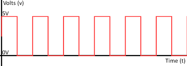
Digital Signal
A digital signal is a type of signal that represents data as discrete values, typically using binary code (0s and 1s). Digital signals are used in digital electronics and communication systems.-
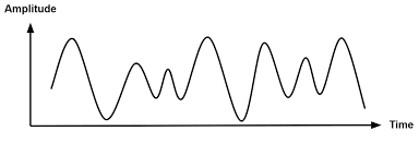
Analog Signal
An analog signal is a continuous signal that can take on any value within a certain range. Analog signals are used in various applications, including audio and video transmission. PWM (Pulse Width Modulation) Signal
PWM is a technique used to encode information in a signal by varying the width of the pulses. It is commonly used for controlling the power delivered to electrical devices, such as motors and LEDs.
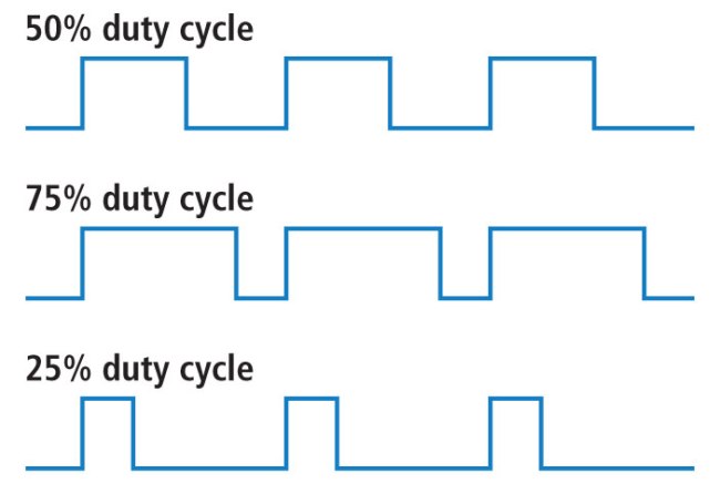
For example, to make an LED light at 50% of its full brightness, we set the duty cycle to 50%. For 30% of full brightness, we set it to 30%, and so on.
Here is a good resource for learning more about PWM: link
How to Test Signals?
To test signals, you can use various tools such as oscilloscopes and multimeters. These tools allow you to visualize and measure the characteristics of different types of signals.
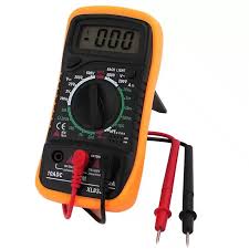
Multimeter
Oscilloscope
A multimeter is a tool used to measure basic electrical quantities such as voltage, current, and resistance in a circuit. It displays the measured value as a single numerical reading, representing the electrical condition at a specific moment in time.
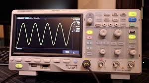
An oscilloscope is a device used to visualize and analyze the waveform of electrical signals. It provides a graphical representation of voltage over time, allowing you to observe the shape, frequency, and amplitude of the signal.
Our Test
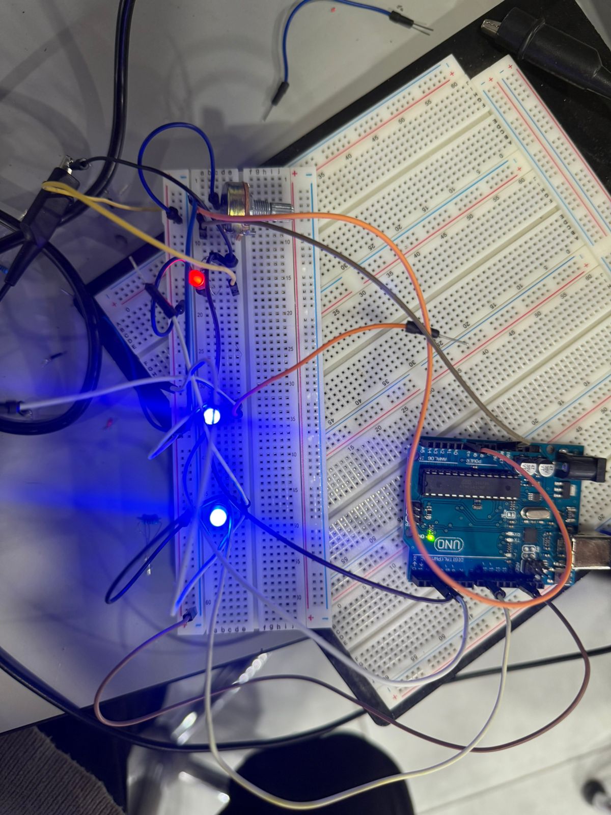
For our test, we will use an Arduino to generate the three types of signals (digital, analog, and PWM), and then use a multimeter and oscilloscope to measure and visualize them.
- Pin 2: Digital Signal (ON/OFF)
- Pin 3: Analog Signal (using a potentiometer to vary the voltage)
- Pin 4: PWM Signal (using analogWrite to vary the duty cycle)
Setup
We built a simple circuit with an Arduino that includes three LEDs, each connected to a different pin and driven by a different type of signal.
Code
Here is the Arduino code we used to generate the signals:
                        // Pin definitions
const int digitalLedPin = 2;   // Digital LED
const int analogLedPin = 3;    // LED controlled by potentiometer
const int pwmLedPin = 9;       // PWM LED

const int potPin = A0;         // Potentiometer

void setup() {
  pinMode(digitalLedPin, OUTPUT);
  pinMode(analogLedPin, OUTPUT);
  pinMode(pwmLedPin, OUTPUT);
}

void loop() {
  // 1. Digital LED: blink every 1 second
  digitalWrite(digitalLedPin, HIGH);
  delay(500);
  digitalWrite(digitalLedPin, LOW);
  delay(500);

  // 2. Analog LED: brightness controlled by potentiometer
  int potValue = analogRead(potPin);                  // 0-1023
  int analogBrightness = map(potValue, 0, 1023, 0, 255);
  analogWrite(analogLedPin, analogBrightness);

  // 3. PWM LED: fixed brightness (example 128 out of 255)
  analogWrite(pwmLedPin, 128);

  delay(50); // small delay
}
Here is the Arduino code file: week6.ino
Multimeter Test
- Measure the voltage across the blinking LED that is used to implement the digital signal.
- Measure the voltage across the potentiometer that is used to implement the analog signal.
- Measure the voltage across the PWM LED at different duty cycles.
Oscilloscope Test
- Visualize the waveform of the blinking LED (digital signal).
- Visualize the waveform of the potentiometer signal (analog signal).
- Visualize the waveform of the PWM signal at different duty cycles.
Conclusion
In this week's assignment, we explored the fundamentals of electronics design by testing different types of electrical signals using an Arduino, multimeter, and oscilloscope. We successfully generated and visualized digital, analog, and PWM signals, gaining a deeper understanding of their characteristics and applications in electronic circuits.