Week 8: Electronics Production
This week focuses on the processing workflow of transforming schematic layouts into tangible hardware, testing the mechanical limits of CNC trace milling, characterizing design parameters, and implementing alternative PCB generation streams through standard boardhouses.
Group Assignment Requirements:
- Characterize the design rules for your in-house PCB production process: document the settings for your machine.
- Document the workflow for sending a PCB to a boardhouse.
- Document your work to the group work page and reflect on your individual page what you learned.
Working with Roland SRM-20
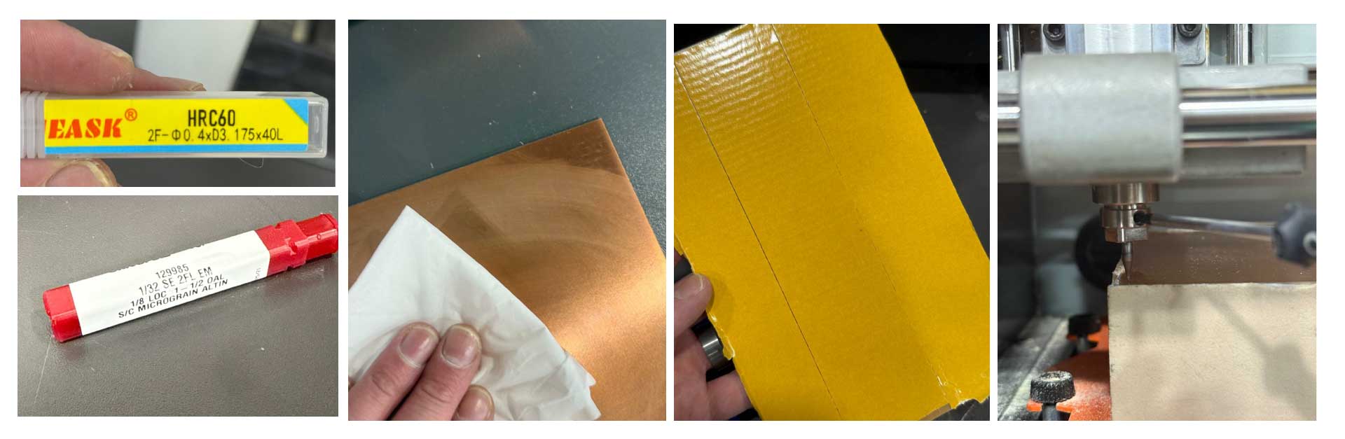
The Roland SRM-20 is a compact mini-milling machine, and we learned it is most suitable to mill the traces on a PCB board. A key difference in the world of milling machines is that the Roland has a fixed spindle, and the bed moves relative to its position. Another key difference is that the Roland milling machine is compatible with a finer range of mill ends. In this week, we used the 1/64in (0.4mm), the 1/32in (0.8mm), and HRC60- 2F- D0.4 X D3.175 X 40L ends.
1/32 SE 2FL EM , 1/8 LOC 1-1/2 OAL , S/C MICROGRAIN ALTIN
| Specification | Breakdown | Description |
|---|---|---|
| 1/32 | Cutting Diameter | The width of the cut (0.03125"). |
| SE | Commonly Single End | Cutting teeth are on one end only. |
| 2FL | 2 Flutes | Two spiral grooves; provides maximum space for chip evacuation. |
| EM | End Mill | The tool category (used for profile and slot milling). |
| 1/8 LOC | Length of Cut | The length of the sharp, fluted cutting edge (0.125"). |
| 1-1/2 OAL | Overall Length | The total length of the tool from top to bottom (1.50"). |
| S/C | Solid Carbide | The tool material; provides high rigidity for precision. |
| Micrograin | Carbide Grade | Ultra-fine grain structure that prevents edge chipping. |
| AlTiN | Coating | Aluminum Titanium Nitride; high-heat coating for hard metals. |
HRC60- 2F- D0.4 X D3.175 X 40L
| Specification | Breakdown | Description |
|---|---|---|
| HRC60 | Hardness Rating | Designed to cut materials with a hardness up to 60 Rockwell C (hardened steels). |
| 2F | 2 Flutes | Two cutting edges; allows for larger chip clearance in micro-milling. |
| D0.4 | Cutting Diameter | The diameter of the cutting tip is 0.4mm (approx. 0.0157"). |
| D3.175 | Shank Diameter | The diameter of the base is 3.175mm (exactly 1/8"), standard for most collets. |
| 40L | Overall Length | The total length of the tool is 40mm (approx. 1.57"). |
Roland SRM-20 Overview & Design Rules
| Feature | Specification / Process Boundary |
|---|---|
| Workpiece Table Size | 232.2 (X) x 156.6 (Y) mm (9.14 x 6.17 inches) This is where the spoiler board is placed |
| Spoiler Board (Wasteboard) | Sacrificial MDF/Acrylic protective layer for through-cutting / PCB milling |
| X, Y, Z Operation Strokes | 203.2 (X) x 152.4 (Y) x 60.5 (Z) mm (8 x 6 x 2.38 inches) |
| Distance (Collet Tip to Table) | Maximum 130.75 mm (5.15 inches) |
| Loadable Workpiece Weight | 2 kg (4.4 lbs) |
| Operating Speed | 6 – 1,800 mm/min (0.24 – 70.87 inches/min) |
| Mechanical Resolution | 0.000998594 mm/step (0.0000393 inches/step) |
| Software Resolution | 0.01 mm/step (RML-1) or 0.001 mm/step (NC code) |
| Spindle Rotation Speed | Adjustable 3,000 – 7,000 RPM (Set to 7,000 RPM for traces) |
| Drive System | Stepping motor |
Pre-Cutting Process & Workflow
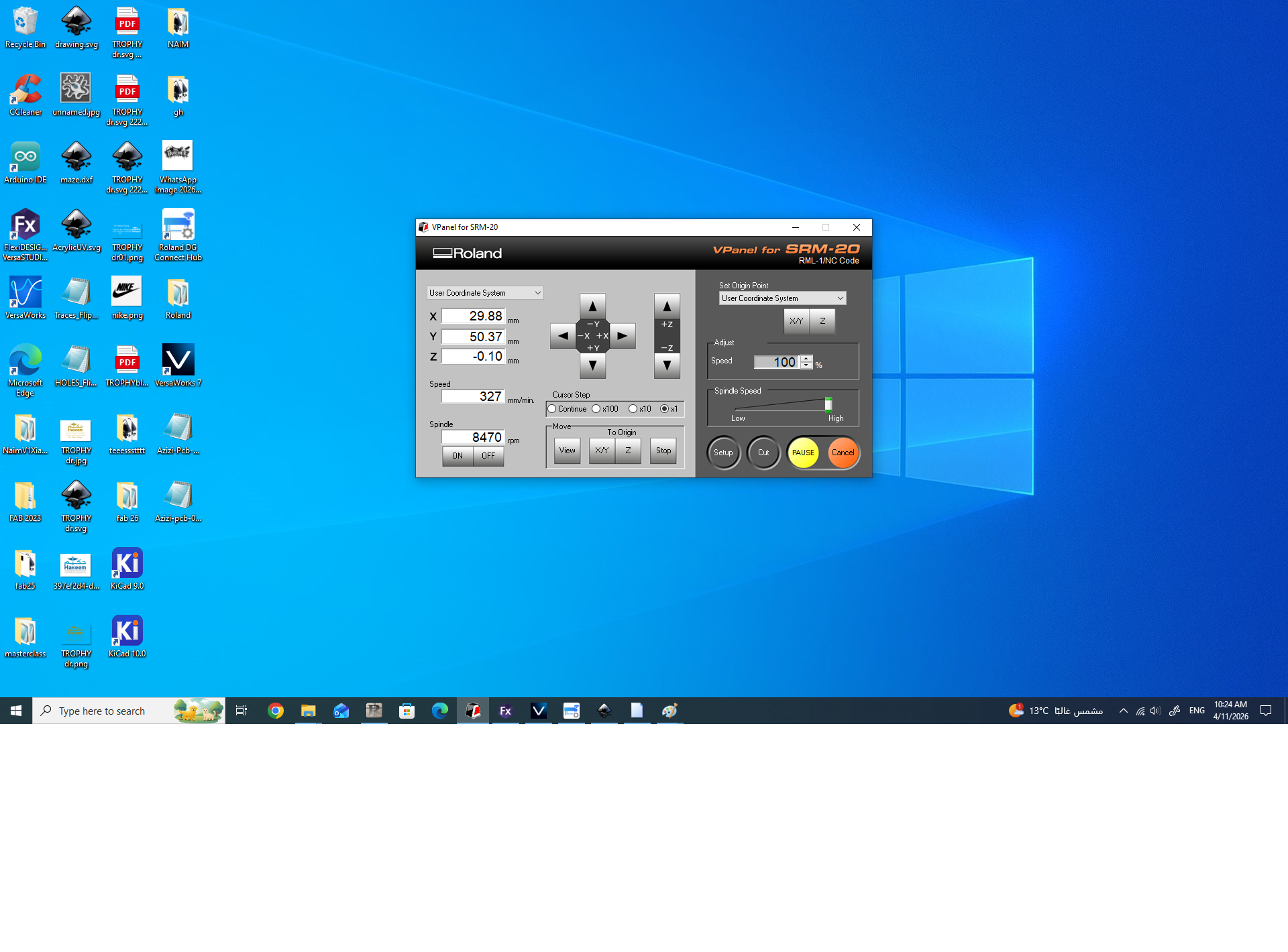
Clean, mount, and calibrate the Z-axis as shown below, and then start your program following the step-by-step sequence.
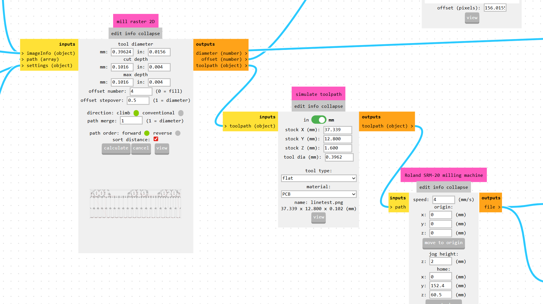
Using Mods Project We prepared the G-Code files for the traces and milling, here we learned how to preset the different end mills
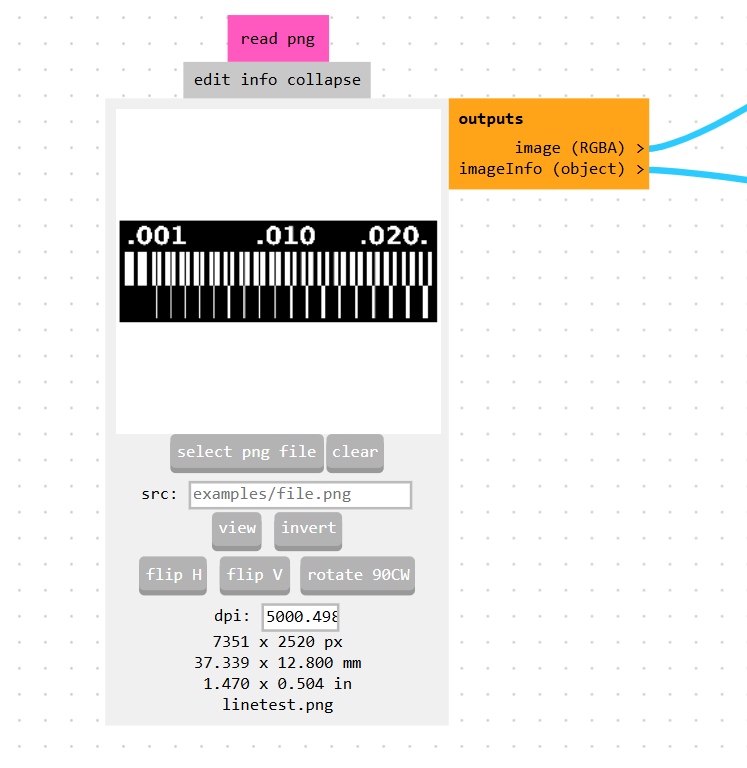
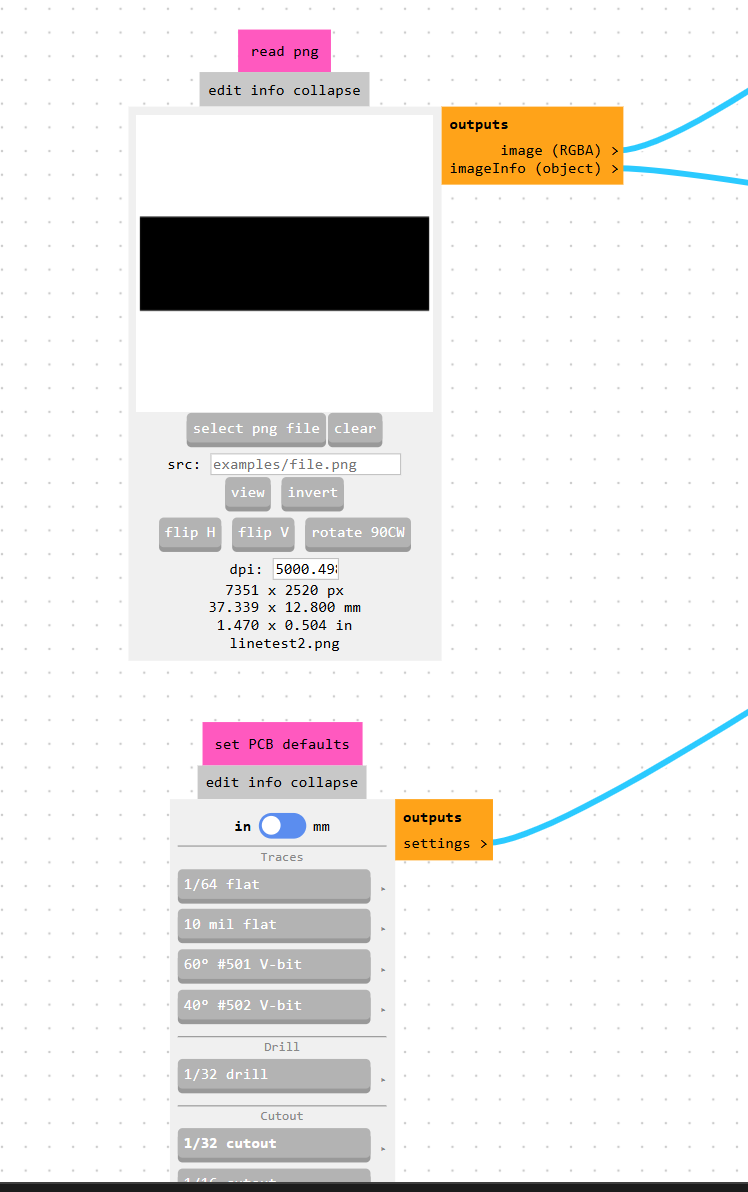
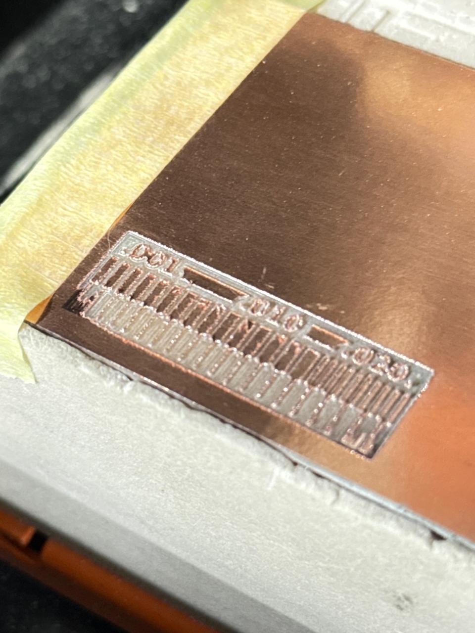
By importing the 2D PNG file into the "read png" node, we verified that the image resolution was correctly calibrated to 5000.498 dpi, which accurately sets the physical board dimensions to 37.339 x 12.800 mm. We also used the "set PCB defaults" node as a quick baseline supervisor to easily toggle between the 1/64" flat end mill for superficial trace isolation and the 1/32" tool for structural contour cutting.


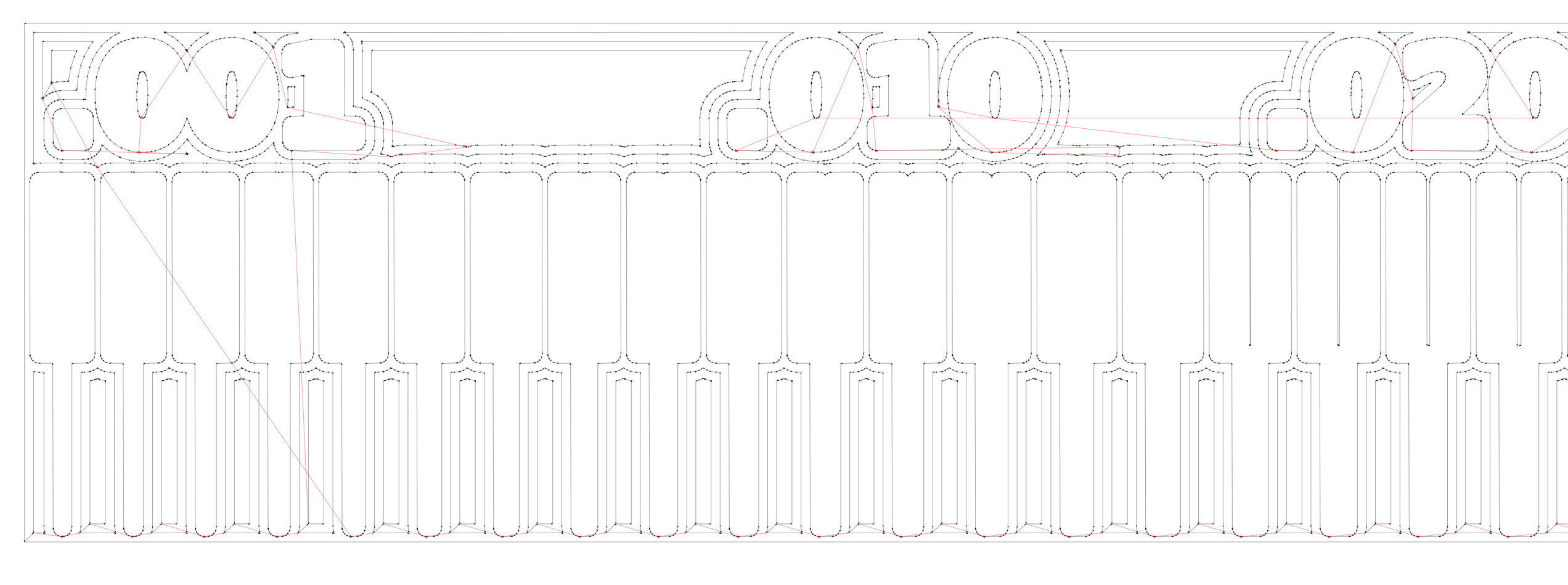
For the trace isolation process, we adjusted the settings inside the "mill raster 2D" node, specifying a tool diameter of 0.39624 mm and a single-pass cut depth of 0.1016 mm to cleanly shave off the top copper layer without drilling into the fiberglass core. We set the offset number to 4 with a 0.5 stepover, which creates four overlapping concentric paths around our traces to clear out enough surrounding copper and prevent any accidental solder bridging later.
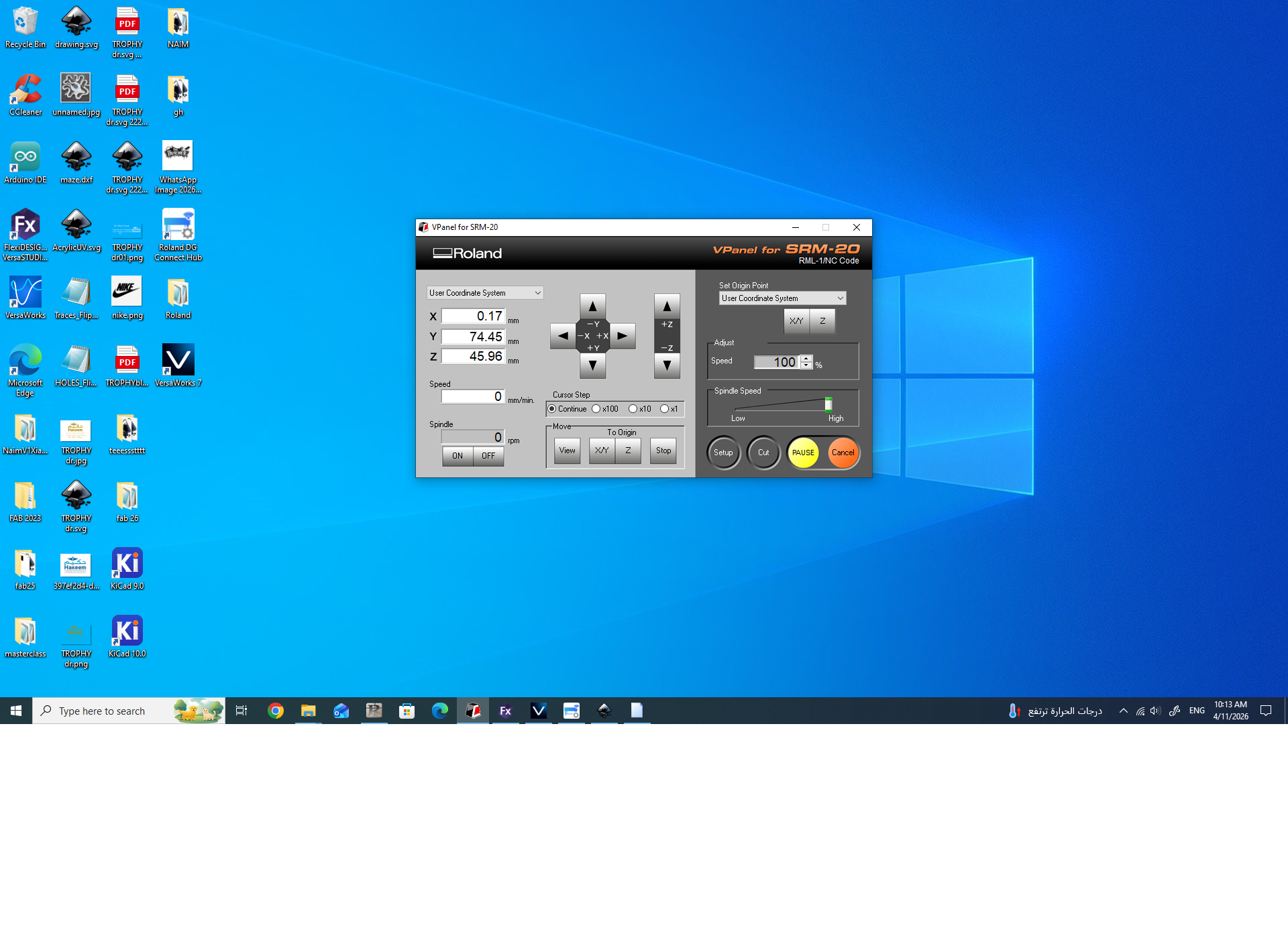
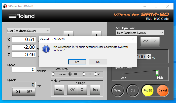
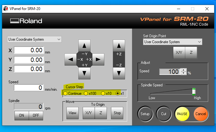
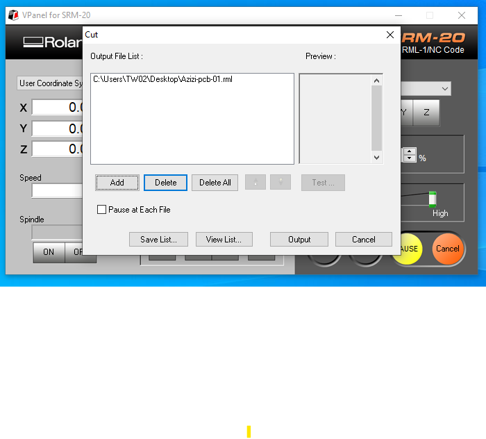
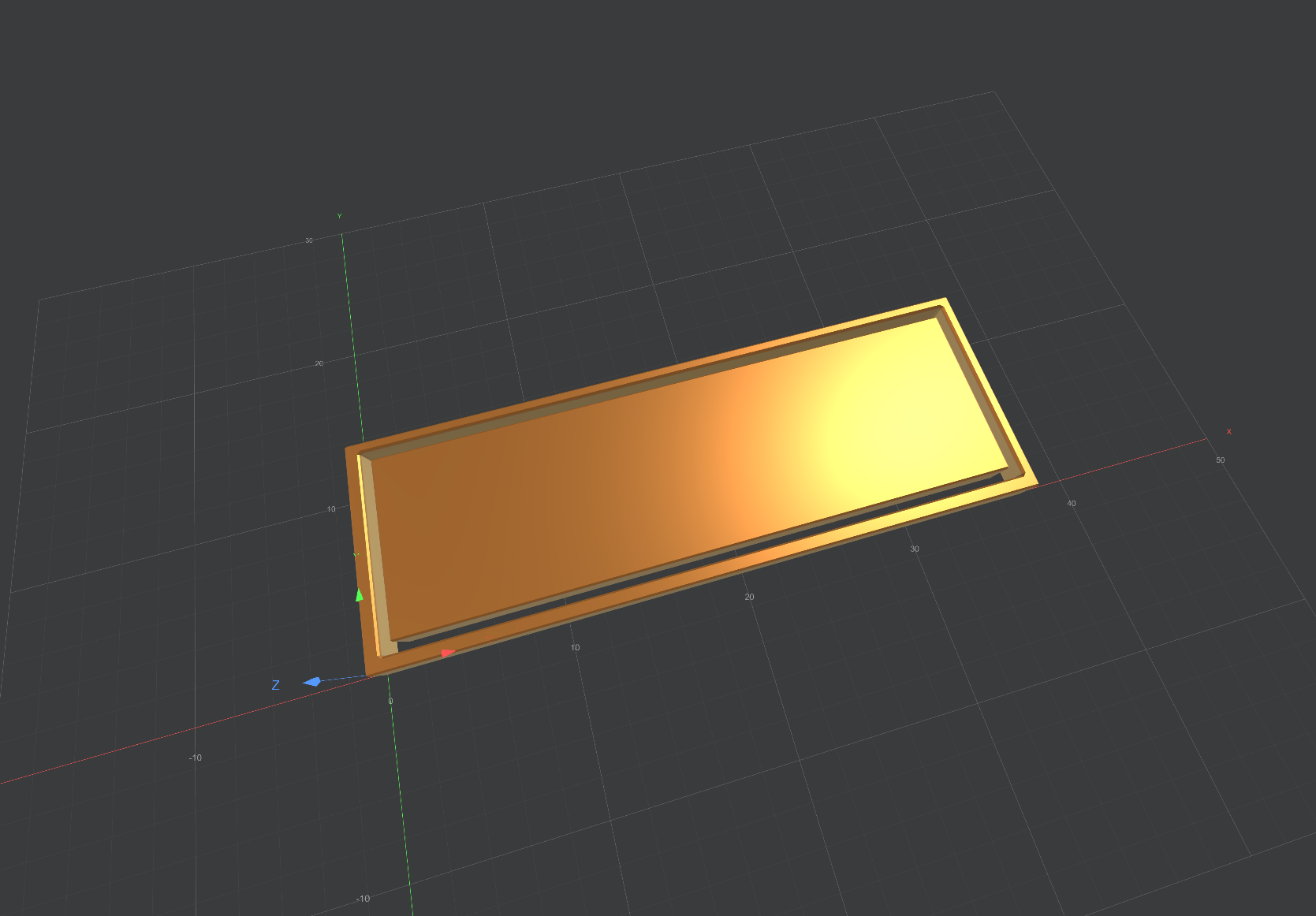
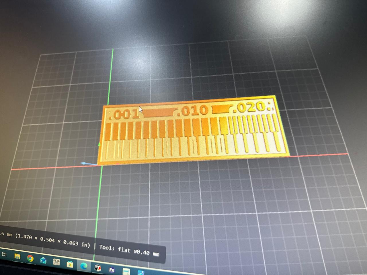
Finally, we simulated the generated toolpath vectors over our 1.600 mm thick stock material to visually validate the machine paths before sending the final file to the Roland SRM-20 milling machine node. We configured a safe processing feed rate of 4 mm/s to prevent fragile bit breakage, established our precise surface origin points, and programmed a 2 mm jog height alongside a convenient custom home parking coordinate to finish the job cleanly.
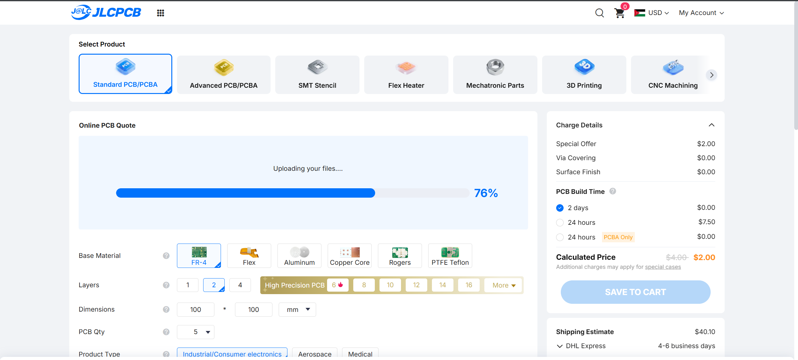
Commercial Fabrication Pipeline: Ordering from JLCPCB
When transition from in-house milling to external scale manufacturing is required, the standard commercial sequence for processing an order through JLCPCB follows these steps:
- Account Authentication: Access the vendor platform by logging into your existing credentials or establishing a new developer profile on the registry portal.
-
Gerber Archive Submission:
Upload the compressed compilation package (typically a
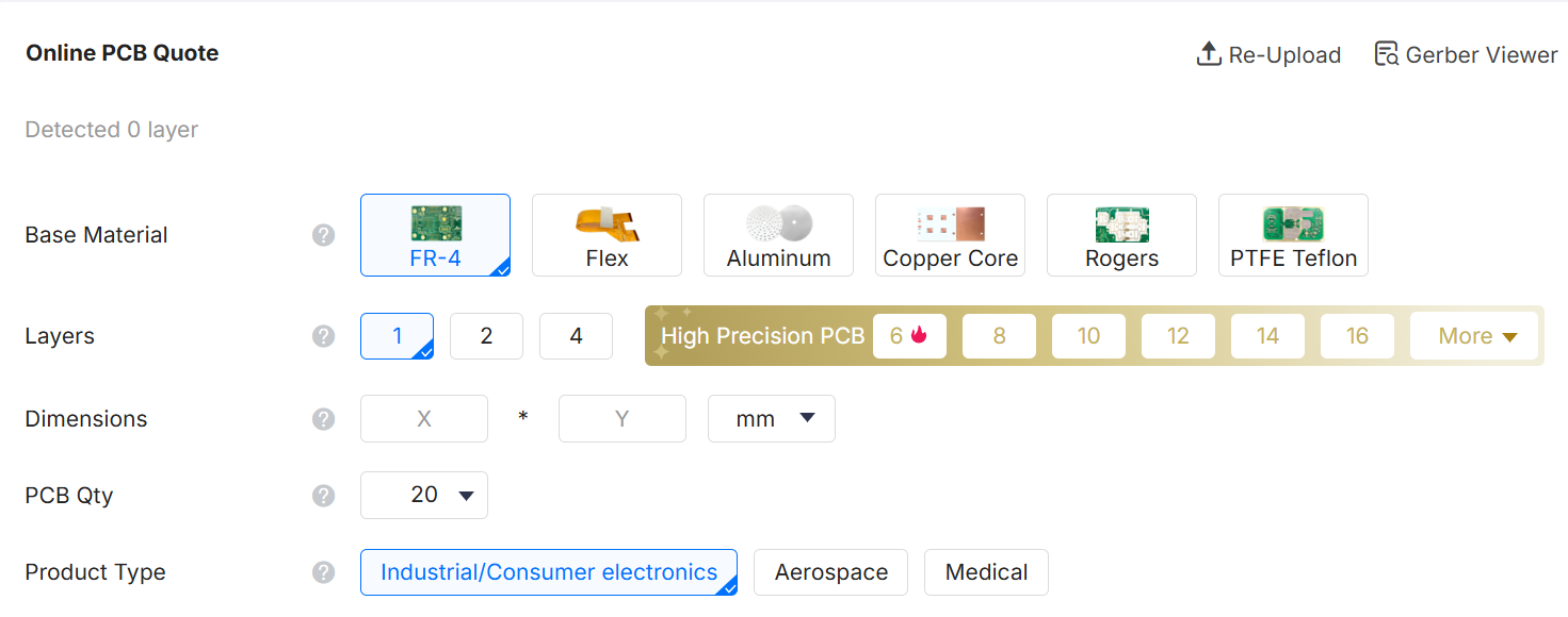
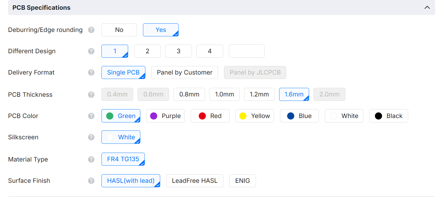
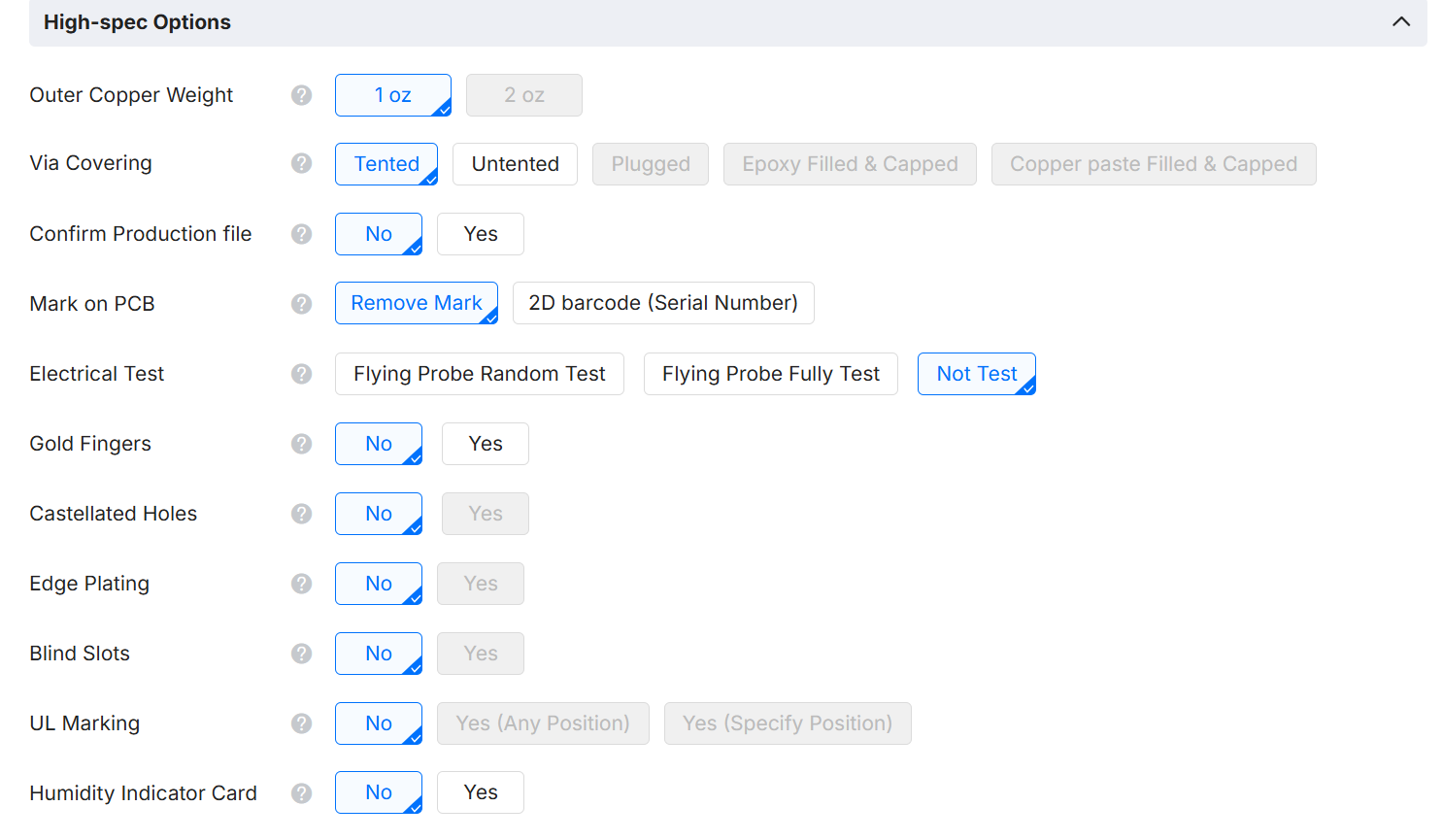
.zipor.rarfile) containing your completed layout vectors. Ensure all structural layers, trace pathways, and profile boundary files are fully included and uncorrupted. - Configuring Manufacturing Metrics: Input the precise physical parameters required for the production batch. Define key variables including unit quantity, substrate thickness (standard 1.6mm), copper cladding density, solder resist aesthetics, and final pad surface treatments.
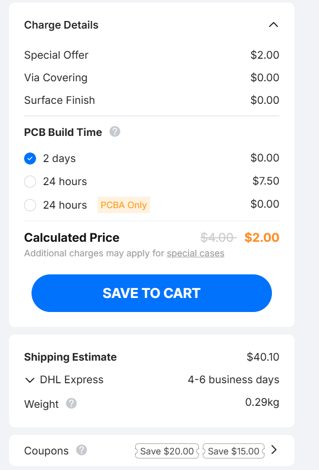
- Data Validation and Pricing Audit: Carefully evaluate the automated structural render, verifying that the processed specifications, batch quantities, and real-time cost estimations align with your design intents.
- Cart Commit: Once configuration parameters are verified against the visual inspector tool, commit the compiled asset stack to your shopping cart.
- Logistics Set-Up: Advance to the processing terminal to designate the exact shipping destination address and select the optimal courier service tier based on lead times.
- Financial Settlement: Authorize the transactional total using your preferred payment infrastructure, such as credit instruments, PayPal, or institutional bank wire routing.
- Production Phase Queue: Upon payment authorization, the design package transitions directly to the factory floor. Total fabrication lead time will adapt automatically based on design density, multi-layer routing complexity, and selected surface finishes.
- Real-Time Progress Oversight: Monitor active production milestones, automated optical inspection (AOI) checklists, and subsequent carrier tracking numbers via your primary account dashboard.
- Hardware Delivery: Conclude the deployment cycle by receiving the finalized, professionally masked, and safely packaged physical circuit boards at your specified shipping location.
Reflection & Key Insights Learned
Through our characterization test matrices and comparative processing with external factories, we acquired several functional operational reflections:
- Levelling Errors: Perfect Z-axis manual alignment across FR4 substrates is highly critical. Minimal deviations in tape adhesion thickness underneath the stock material cause tracing failures or tool snapping.
- Tool Management Boundaries: While the 1/64" endmill cuts pristine high-density trace gaps, it is highly fragile compared to the heavy material removal capacity of a 1/32" tool. Tool isolation geometries should maximize clearing widths to prevent accidental bridges during solder operations.
- In-House vs Commercial Trade-Offs: CNC rapid-prototyping offers immediate verification speeds (under 30 minutes) but lacks via plating and structural solder masks. Conversely, commercial production runs provide professional multi-layer reliability at the cost of shipping lead times.