Week 11: Networking and Communications
This week focuses on networking and communications, specifically the protocols and standards used in modern communication systems.
For this week, we will explore wired communication protocols and compare them, such as:
- UART
- I2C
Wired Communication Protocols
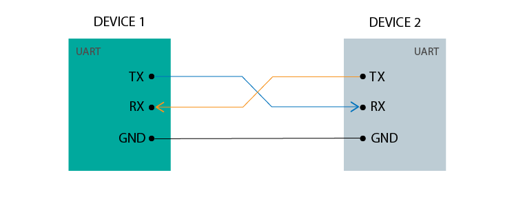
UART (Universal Asynchronous Receiver/Transmitter):
UART is a simple serial communication protocol that uses two wires (TX and RX) to transmit data between devices. It is asynchronous, meaning that there is no clock signal to synchronize the data transmission. UART is commonly used for communication between microcontrollers and peripherals such as sensors, displays, and GPS modules.
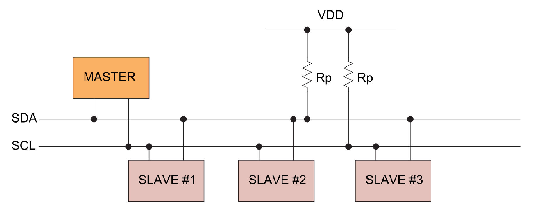
I2C (Inter-Integrated Circuit):
I2C is a synchronous serial communication protocol that uses two wires (SDA and SCL) to transmit data between devices. It is a multi-master protocol, meaning that multiple devices can be connected to the same bus and can take turns transmitting data. I2C is commonly used for communication between microcontrollers and peripherals such as sensors, displays, and EEPROMs.
Testing Communication Protocols
For testing, I will use two Arduino Uno boards. I will apply the same test for both protocols by connecting a push button on one board and an LED to the other so the communication can be tested.
UART
- The circuit connection diagram:
- Here is the sender program which uploaded to the first Arduino:
For testing UART, I will connect the TX pin of the first Arduino to the RX pin of the second Arduino, and there is no need to connect the other direction since the connection is one-way. I will then write a simple program to send a signal from the first Arduino when the button is pressed, and turn on the LED on the second Arduino when it receives the signal.
#define BUTTON_PIN 7

void setup() {

  pinMode(BUTTON_PIN, INPUT_PULLUP);

  Serial.begin(9600);
}

void loop() {

  int state = digitalRead(BUTTON_PIN);

  if (state == LOW) {

    Serial.println("1");

  } else {

    Serial.println("0");
  }

  delay(100);
}
In this program, we define a button pin and set it as an input with a pull-up resistor. In the loop, we read the state of the button and send "1" when the button is pressed (active LOW) and "0" when it is not pressed. We also add a small delay to avoid sending too many messages in a short time.
You can download the code from here.
#define LED_PIN 10

void setup() {

  Serial.begin(9600);

  pinMode(LED_PIN, OUTPUT);

void loop() {

  if (Serial.available()) {

    String msg = Serial.readStringUntil('\n');

    msg.trim();

    Serial.print("Received: ");
    Serial.println(msg);

    if (msg == "1") {

      digitalWrite(LED_PIN, HIGH);

    } else if (msg == "0") {

      digitalWrite(LED_PIN, LOW);
    }
  }
}
In this program, we define an LED pin and set it as an output. In the loop, we check if there is any data available on the serial port. If there is, we read the message until a newline character, trim any whitespace, and print the received message to the serial monitor. We then check if the message is "1" or "0" and turn the LED on or off accordingly.
You can download the code from here.
I2C
For testing I2C, I will connect the SDA pins of both Arduinos together and the SCL pins of both Arduinos together. I will also connect the GND pins together to ensure a common ground reference. I will then write a simple program to send a signal from the first Arduino when the button is pressed, and turn on the LED on the second Arduino when it receives the signal.
- The circuit connection diagram:
- Here is the sender (master) program, which is uploaded to the first Arduino:
#include <Wire.h>

#define BUTTON_PIN 2

int lastState = HIGH;

void setup() {

  pinMode(BUTTON_PIN, INPUT_PULLUP);

  Wire.begin();
}

void loop() {

  int currentState = digitalRead(BUTTON_PIN);

  if (currentState != lastState) {

    Wire.beginTransmission(8);

    if (currentState == LOW) {

      Wire.write(1);

    } else {

      Wire.write(0);
    }

    Wire.endTransmission();

    lastState = currentState;

    delay(50);
  }
}
In this program, we include the Wire library for I2C communication. We define a button pin and set it as an input with a pull-up resistor. In the loop, we read the current state of the button and compare it with the last state. If there is a change in state, we begin an I2C transmission to the device with address 8. We write "1" when the button is pressed (active LOW) and "0" when it is not pressed. We then end the transmission and update the last state variable. We also add a small delay to avoid sending too many messages in a short time.
You can download the code from here.
#include <Wire.h>

#define LED_PIN 10

void setup() {

  pinMode(LED_PIN, OUTPUT);

  Serial.begin(9600);

  Wire.begin(8);

  Wire.onReceive(receiveEvent);
}

void loop() {
}

void receiveEvent(int howMany) {

  while (Wire.available()) {

    int x = Wire.read();

    Serial.print("Received: ");
    Serial.println(x);

    if (x == 1) {

      digitalWrite(LED_PIN, HIGH);

    } else {

      digitalWrite(LED_PIN, LOW);
    }
  }
}
In this program, we include the Wire library for I2C communication. We define an LED pin and set it as an output. In the setup function, we initialize the serial communication and join the I2C bus with address 8. We also register a receive event handler function that will be called whenever data is received on the I2C bus. In the receiveEvent function, we read the incoming data and print it to the serial monitor. We then check if the received value is 1 or 0 and turn the LED on or off accordingly.
You can download the code from here.
Conclusion:
In my opinion, working with I2C was much easier and required less debugging than working with UART. I2C also made communication between multiple devices simpler and more organized because both boards shared the same communication lines.
In conclusion, both UART and I2C are widely used communication protocols in embedded systems, each with its own advantages and disadvantages. UART is simple and easy to use, making it ideal for short-distance communication between devices. I2C, on the other hand, is more complex but allows multiple devices to be connected to the same bus, making it suitable for larger systems with many peripherals. When choosing between the two protocols, it is important to consider the specific requirements of your project and the devices you are using.