Machine Design - Digital Adjustable Mannequin
A Multi-Axis Parametric Physical Mannequin
Project Planning
The selection process focused on finding a project that maximized the use of digital fabrication while solving a real-world design constraint.
| Criteria | Mannequin Project | Alternative Idea |
|---|---|---|
| Complexity | High (Mechanical + Electronic) | Medium |
| Digital Mfg | 3D Printing, Laser, CNC, PCB | 3D Printing only |
| Modelling | High (Parametric & Kinematic) | Low |
| Scalability | High (Modular segments) | Medium |
| Usability | Professional Tailoring / Fashion | Hobbyist |
Final Decision: Digital Adjustable Mannequin.
Scope
The project aims to create a functional prototype focusing on three primary body measurements: Waist, Bust, and Neck/Shoulders.
Roles and Responsibilities
| Concept and Design | Mohammed Azizi |
| Electronics and Wiring | Malak Al-Sharqawi |
| Video and Poster | Mohammed Azizi |
| Documentation | Collaborative |
Phase 1: Material Selection & Procurement
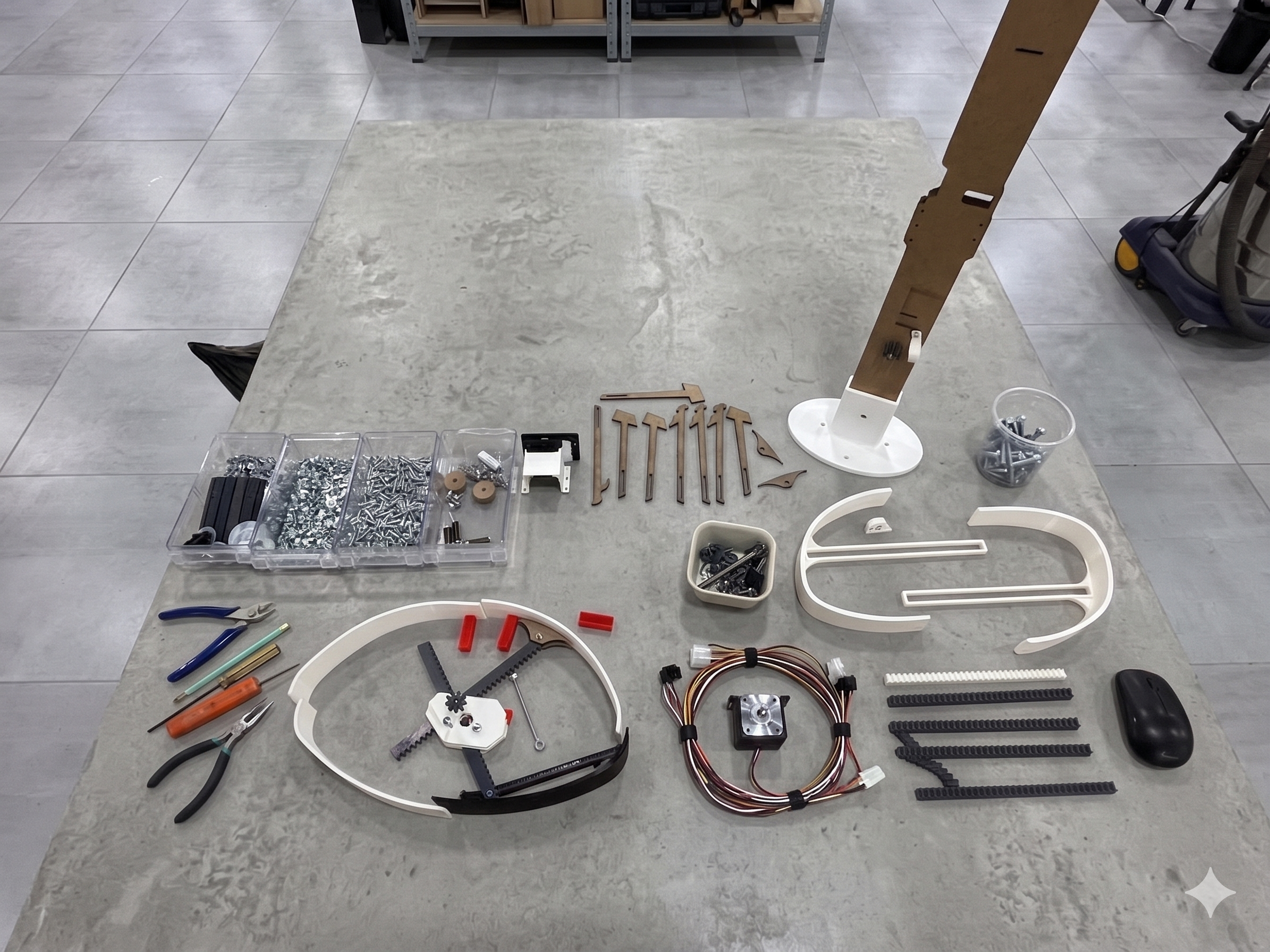
Following our initial discussions, we drafted a list of all components required to bridge the gap between digital design and physical actuation.
Bill of Materials (BOM)
| Category | Item | Description | Quantity |
|---|---|---|---|
| Motor Driver | Arduino Uno R3 | Main Microcontroller | 1 |
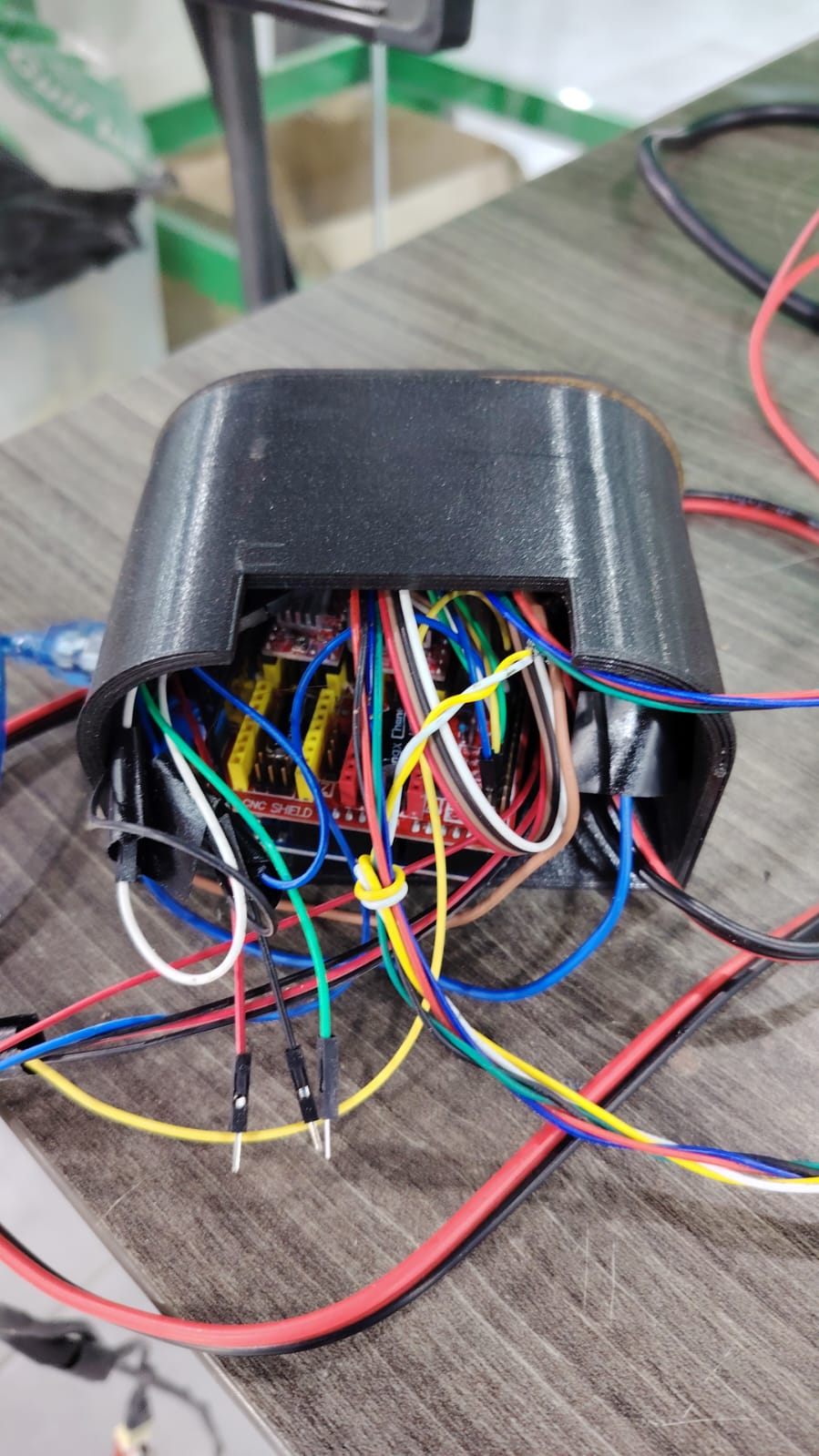
| CNC Shield V3 | Expansion Board | 1 | |
| A4988 Drivers | Stepper Motor Drivers | 2 | |
| Motors | NEMA 17 | Stepper Motors | 2 |
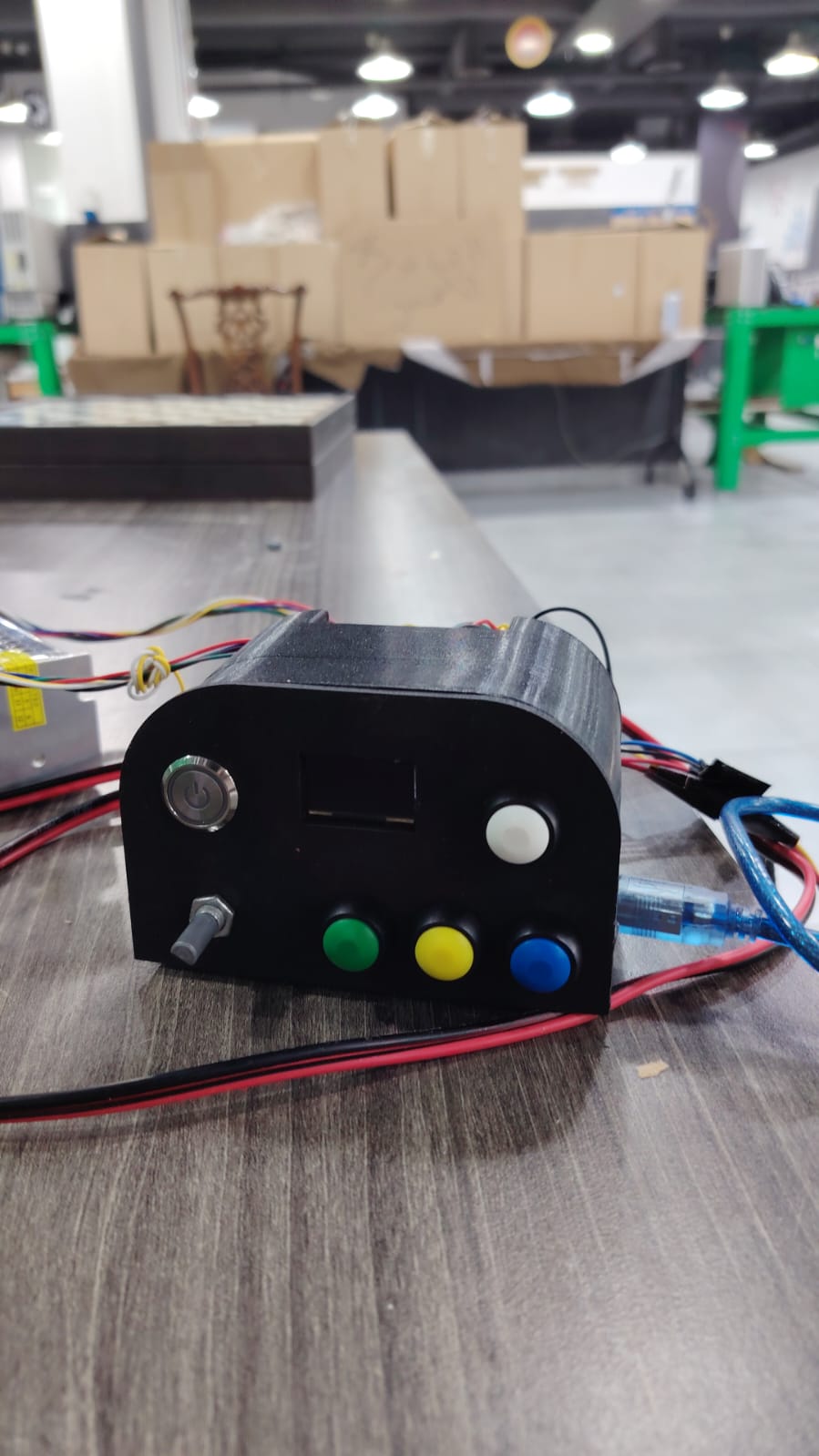
| Input Devices | Rotary Encoder | With push button for menu navigation | 1 |
| Push Buttons | Tactile switches | 4 | |
| Limit Switches | End-stops for homing/calibration | 2 | |
| Display | 0.96" OLED Display | I2C Communication | 1 |
| Power Supply | 12V Power Supply | Dedicated for Motor Rail | 1 |
| USB / 5V Cable | Logic power for Arduino | 1 |
Phase 2: Modelling & Electronics
-
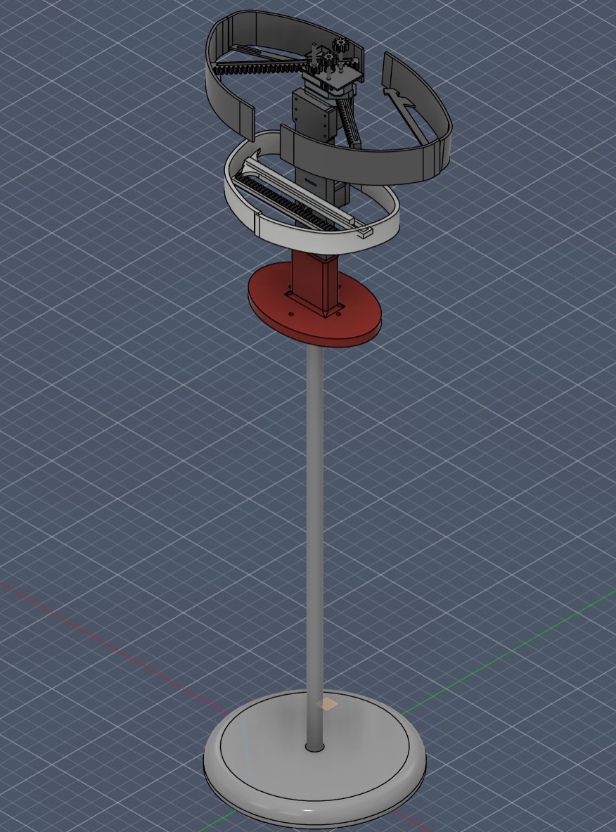
Modelling (Mohammed Azizi)
I created the design models starting with the waist mechanism. This phase included drafting the racks, gears, and the external shell panels.
-
Electronics (Malak Al-Sharqawi)
Investigation into the CNC shield architecture and the logic required to control multiple steppers simultaneously.
-
Assembly & Manufacturing
We utilized the following digital fabrication tools:
- Ultimaker: For high-precision 3D printed mechanical parts.
- Trotec Laser Cutter: For structural support plates and housing.
Phase 3: Prototyping & Calibration
3a: 3D Component Testing
| Part | Material | Walls | Infill | Result |
|---|---|---|---|---|
| External Shell | PLA | 2 | 5% | Success |
| Primary Gear | PETG | 4 | 5% | Success |
| Racks | PETG | 4 | 5% | Success |
| Racks | PLA | 4 | 5% | Success |
| Rack Gear | PETG | 2 | 5% | Failed |
Phase 4: Testing & Iteration
Initial Mechanism Test
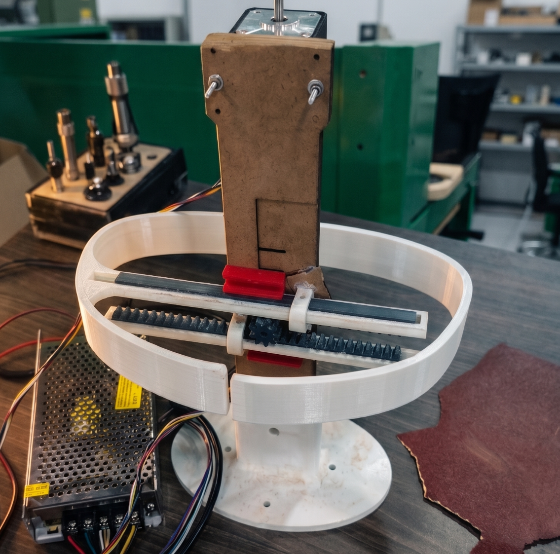
The waist mechanism assembly was successful, but the upper bust mechanism presented significant friction. The motion was not smooth.
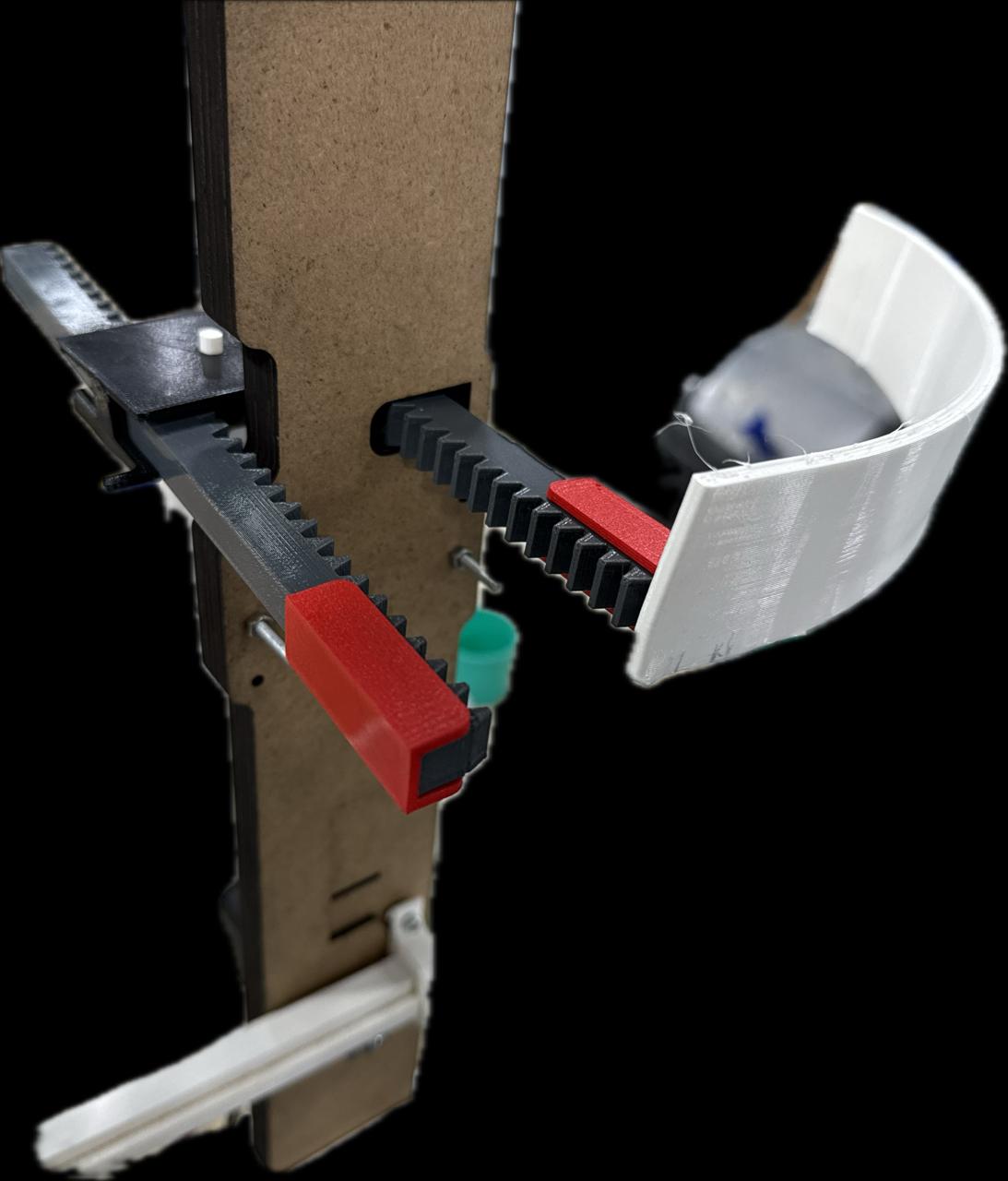
Analysis of the initial gear-driven bust mechanism showing friction points.
Final Results
The transition to the radial expansion mechanism allowed for synchronized, smooth adjustments across all body segments. The prototype successfully responds to digital inputs to match specific anatomical measurements.
Electronic Conenction Diagram