Week 3: Computer Controlled Cutting
Group Assignment Requirements
- Do lab’s safety training
-
Characterize your laser cutter’s:
- Focus
- Power
- Speed
- Rate
- Kerf
- Joint clearance
- Types
-
Documentation
- Document work on the group work page
- Reflect on individual page about what you learned
During this week we started by learning about the machines in CPF Makerspace, primarly focusing on the laser cutting machine, and the vinyl cutter.
Machine Specifications
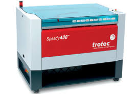
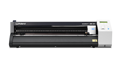
| Specification | Trotec Speedy 400 | Roland GS-24 |
|---|---|---|
| Machine Type | CO₂ Laser Cutter | Vinyl Cutter |
| Function | Cutting & engraving a wide range of materials (wood, acrylic, leather, etc.) | Cutting vinyl and thin materials for decals, signage, stencils |
| Max Power | Up to 120W CO₂ | Blade force 30–350 gf |
| Work Area | 1016 mm × 610 mm | Max cutting width 584 mm |
| Max Speed | Up to 4.3 m/s | Up to 500 mm/s |
| Software Used | Trotec JobControl | Inkscape / Roland CutStudio |
| Datasheet | Trotec Speedy 400 Datasheet | Roland GS-24 Datasheet |
Our Instructor Naim Haj-Ali explained the key concepts of operating the laser cutter and walked us through the tests we performed using 2–3 mm MDF wood.
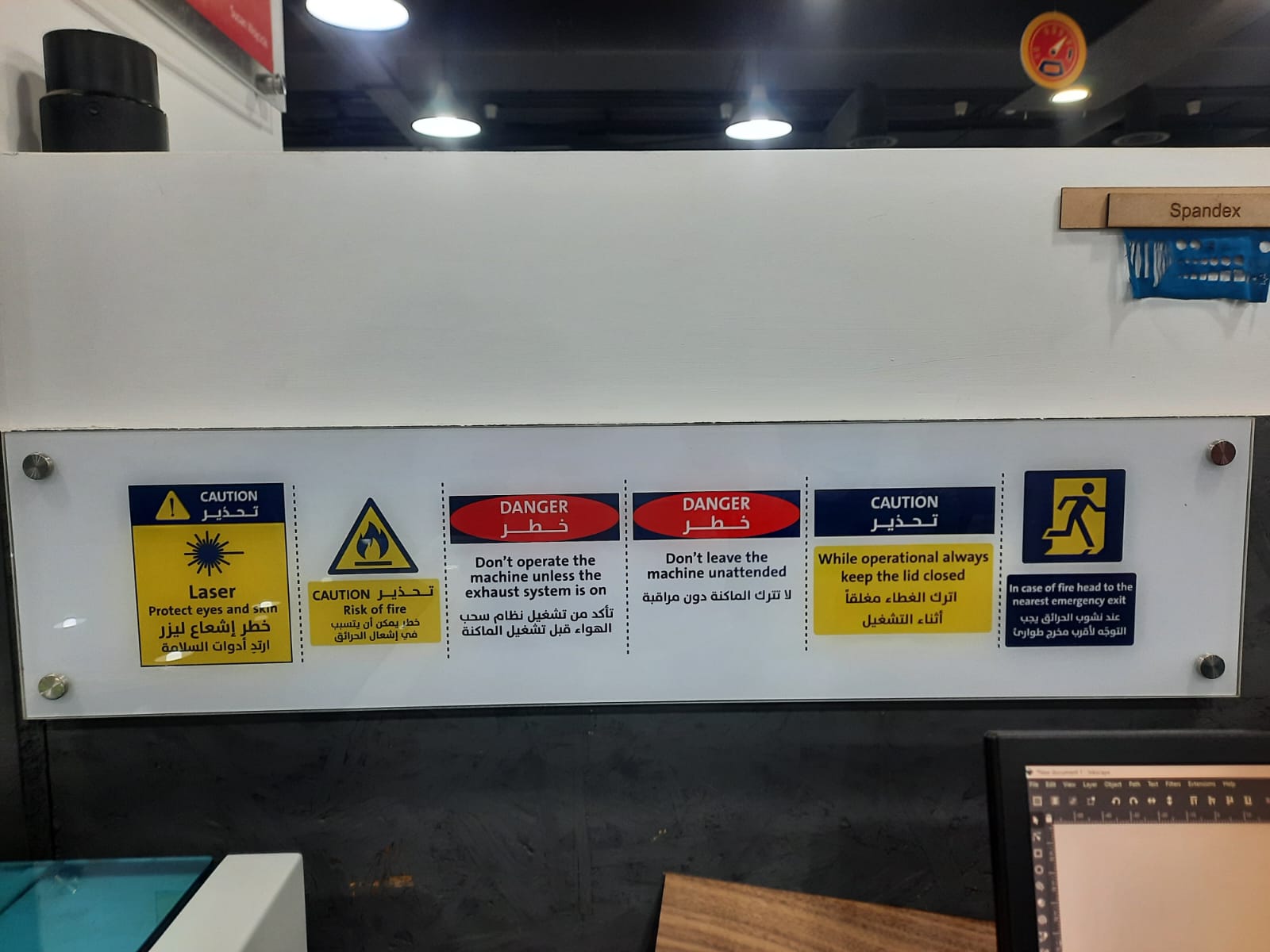
Laser Cutting Safety
- Eye Protection: Always wear appropriate laser safety goggles that are rated for the specific wavelength of the laser being used.
- Exhaust System: Do not operate the machine unless the exhaust system is functioning properly to remove fumes and smoke generated during cutting.
- Supervision: Never leave the laser cutter unattended while it is operating.
- Lid Safety: While operating, always keep the lid closed.
- Material Safety: Only cut materials that are approved for laser cutting. Avoid cutting PVC, vinyl, or other materials that can release toxic gases.
Important Definitions (Laser Cutting)
- Focal Point: The precise distance between the laser lens and the material where the laser beam is most concentrated, producing the smallest and most powerful spot.
- Laser Power: The amount of energy emitted by the laser (measured in watts). Higher power increases cutting ability but may cause more burning.
- Speed: The movement rate of the laser head across the material (mm/s). Higher speed reduces exposure time; lower speed increases material burn.
- Kerf: The width of material removed by the laser beam during cutting.
- Joint Clearance: The intentional gap designed between two interlocking parts to ensure proper fit after accounting for kerf.
Laser Cutting Tests (Material: MDF 2–3 mm)
1) Focal Point Test
- Determines the optimal focus distance.
- Ensures clean cuts and minimal charring.
2) Power vs Speed Test
- Tests different power and speed combinations.
- Identifies settings that fully cut the material without excessive burn marks.
3) Kerf Test
- Measures the material removed by the laser.
- Used to calculate accurate press-fit tolerances.
Note: The tests were performed using 2.3 mm MDF wood, which is a common material for laser cutting .
Focal Point Test Workflow and Results
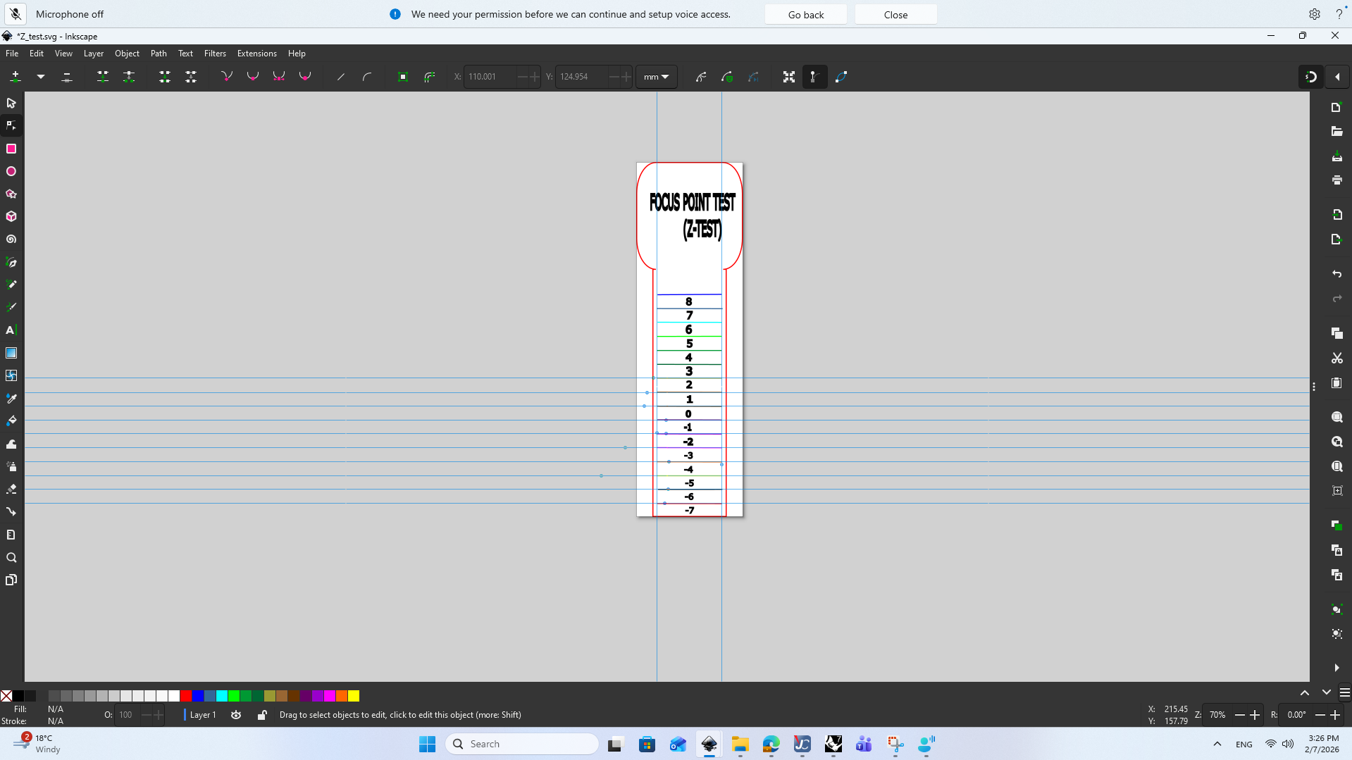
We aimed to find the optimal focal point for cutting MDF 2–3 mm. We created a test design with lines at varying distances from the laser head and observed the cut quality.
- We designed a test pattern with lines at different heights (z-axis) to find the focal point using Inkscape (here is the .svg file) and exported it as a DXF file.
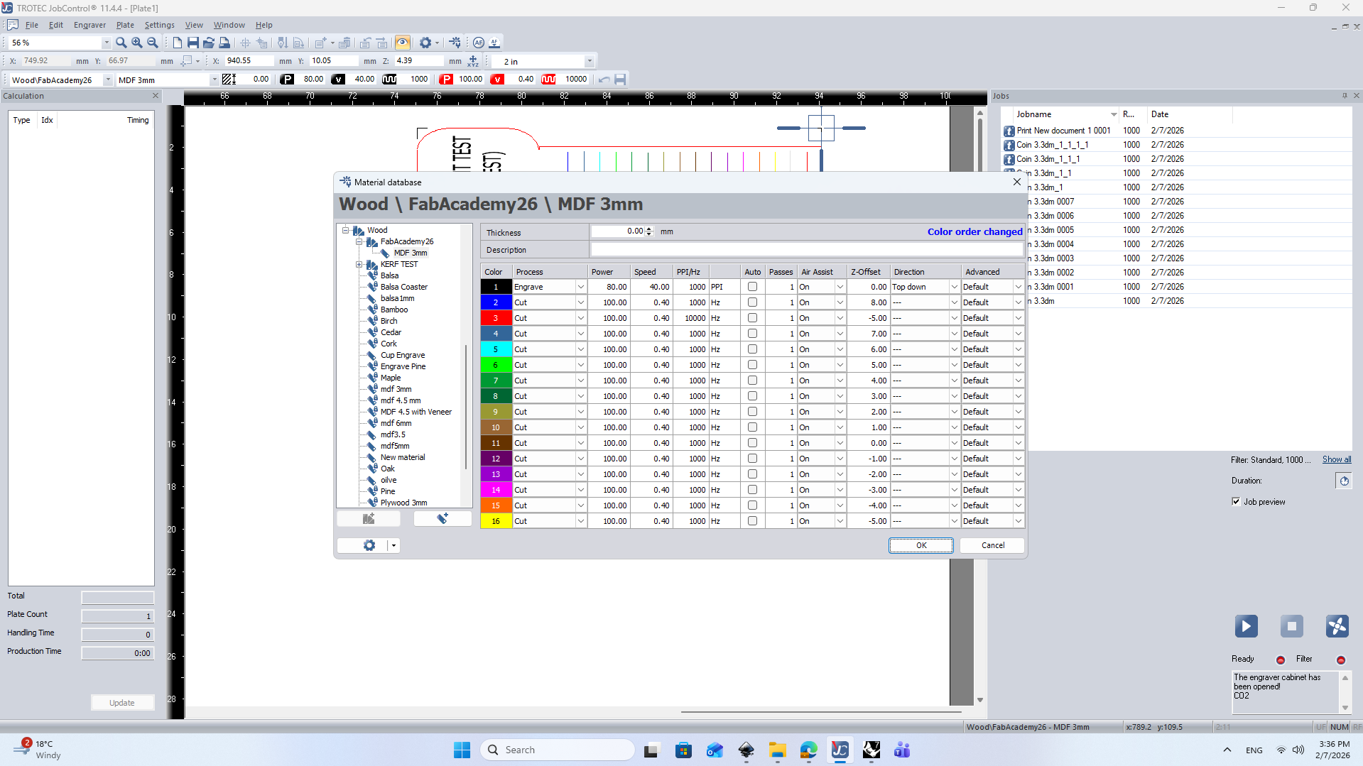
- We imported the DXF file into the Trotec JobControl software, set the laser parameters, and performed the test cuts.
- Then cut the piece.
- We observed the cut quality at different focal points.
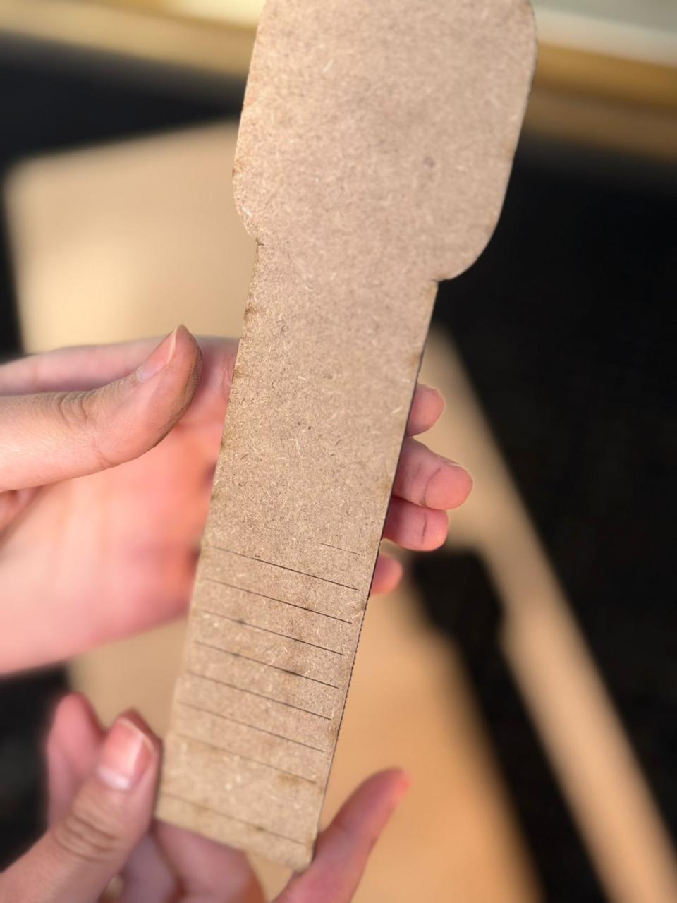
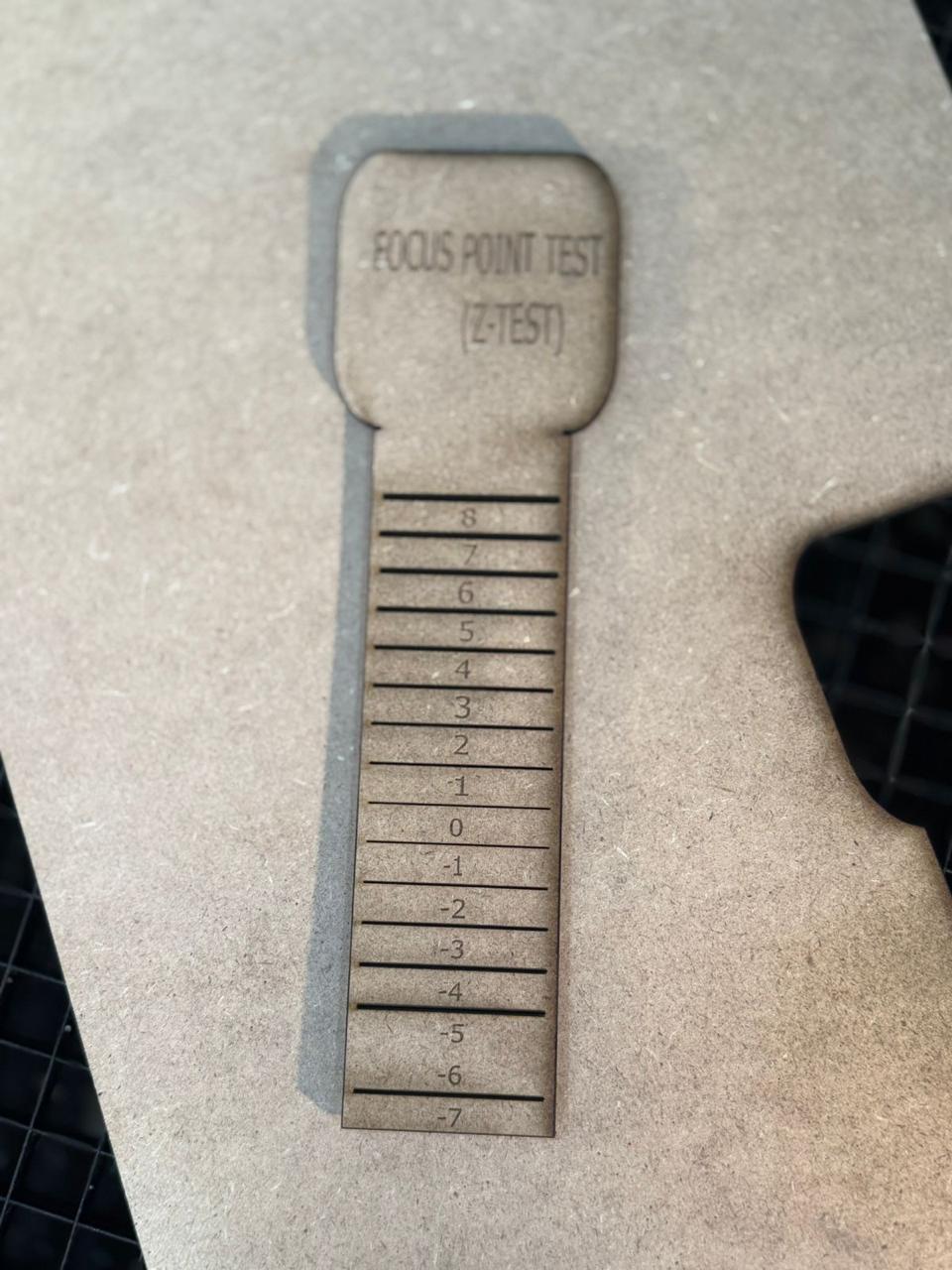
Results
- The optimal focal point for cutting MDF 2–3 mm was found to be at z = 0 mm (the default focal distance).
- At this focal point, the cuts were clean with minimal charring, while deviations from this point resulted in poorer cut quality.
Power VS Speed Test Workflow and Results
The goal of this test was to find the optimum power to speed ratio of cutting MDF 2.3mm (our material).
- We started by creating a template design containg 14-16 circles and engraved text definers such as (Material, Speed, Power) using Autocad.
- We imported the file into Inkscape to define color set strokes, ensure Hairline settings are applied and input different power vs speed values (here is the .svg file).
- Open JC Control and ensure that the cutting settings are well defined (We created a custom setting file).
- Perform the test cuts and observe the results.
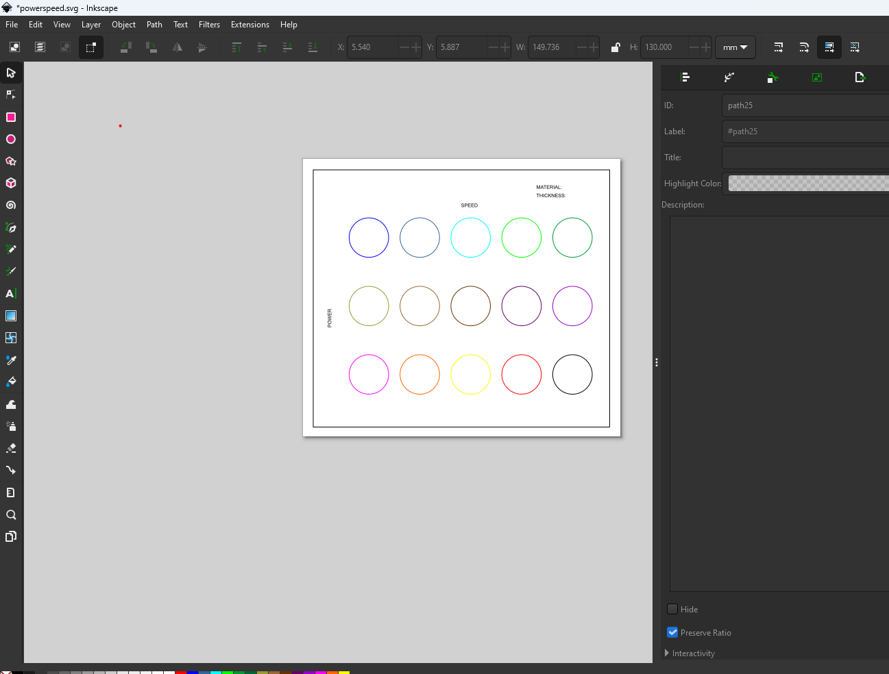
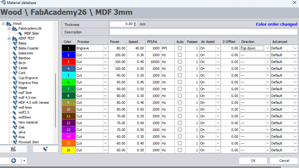
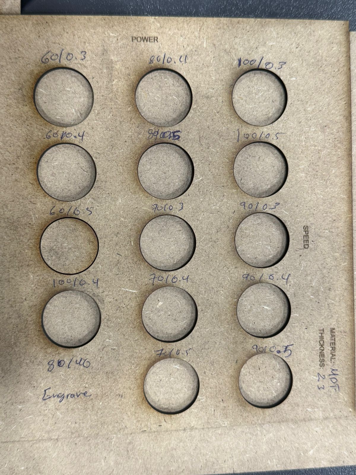
Results
- It was found the ideal power to speed ratio on MDF 2.3 mm was (Power = 60 to 70, Speed = 0.3-0.4).
- This result is based on the optimum focal point found in Focal Point Test (z = 0).
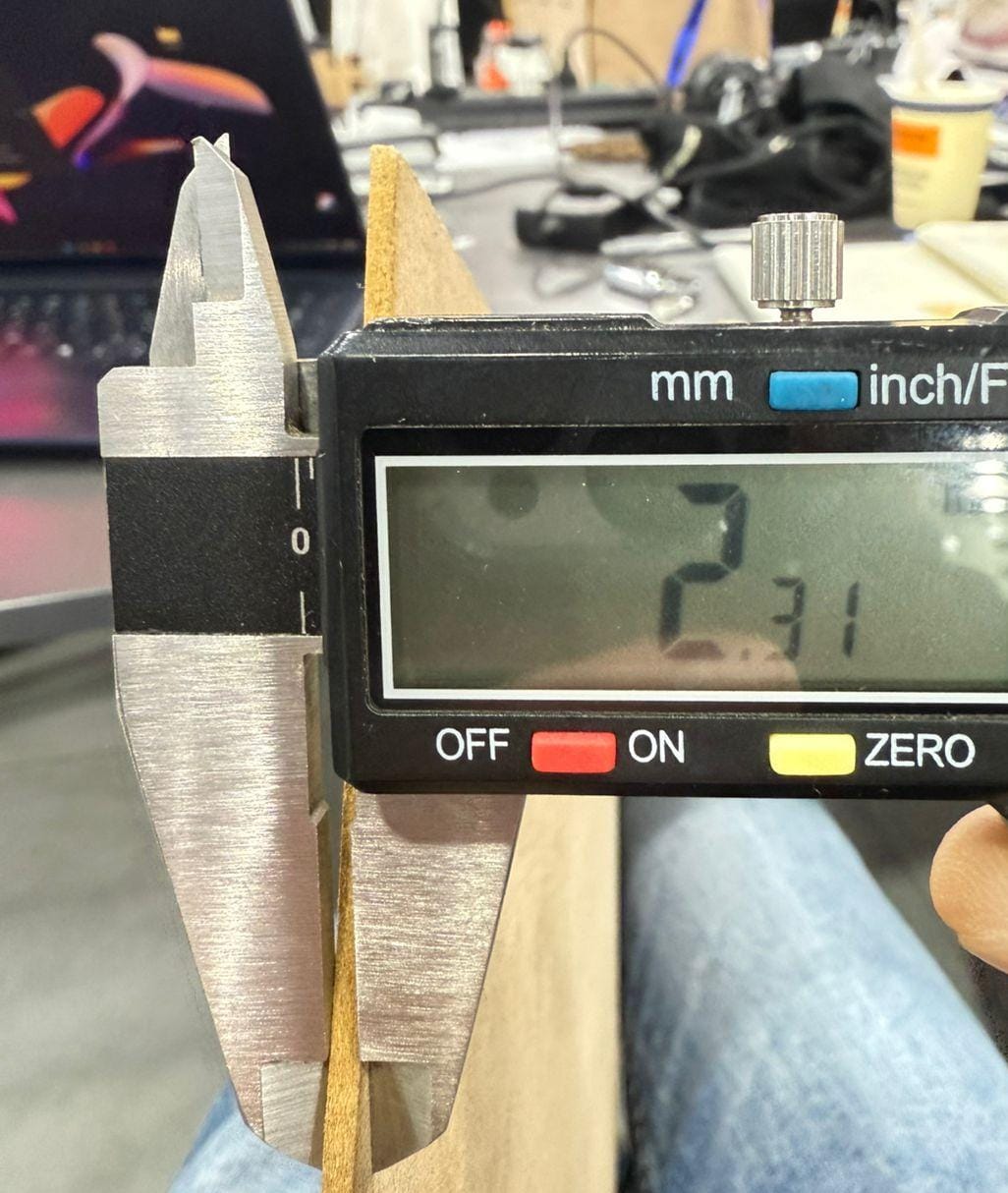
Kerf Test Workflow and Results
The goal of this test was to find and calculate the Kerf Value.
- We started by creating a template design containg slots inceasing in gap size by 0.05 mm and engraved text definers such as (Material, Actual Readings vs CAD dimensions) here is the .dxf file.
- Import the DXF file into Inkscape to define color set strokes, ensure Hairline settings are applied and input different power vs speed values.
- Manually measure the cut pcs using digital callipers and compare them with the cut slots.
- Use a piece of the same material to define the perfect joint.
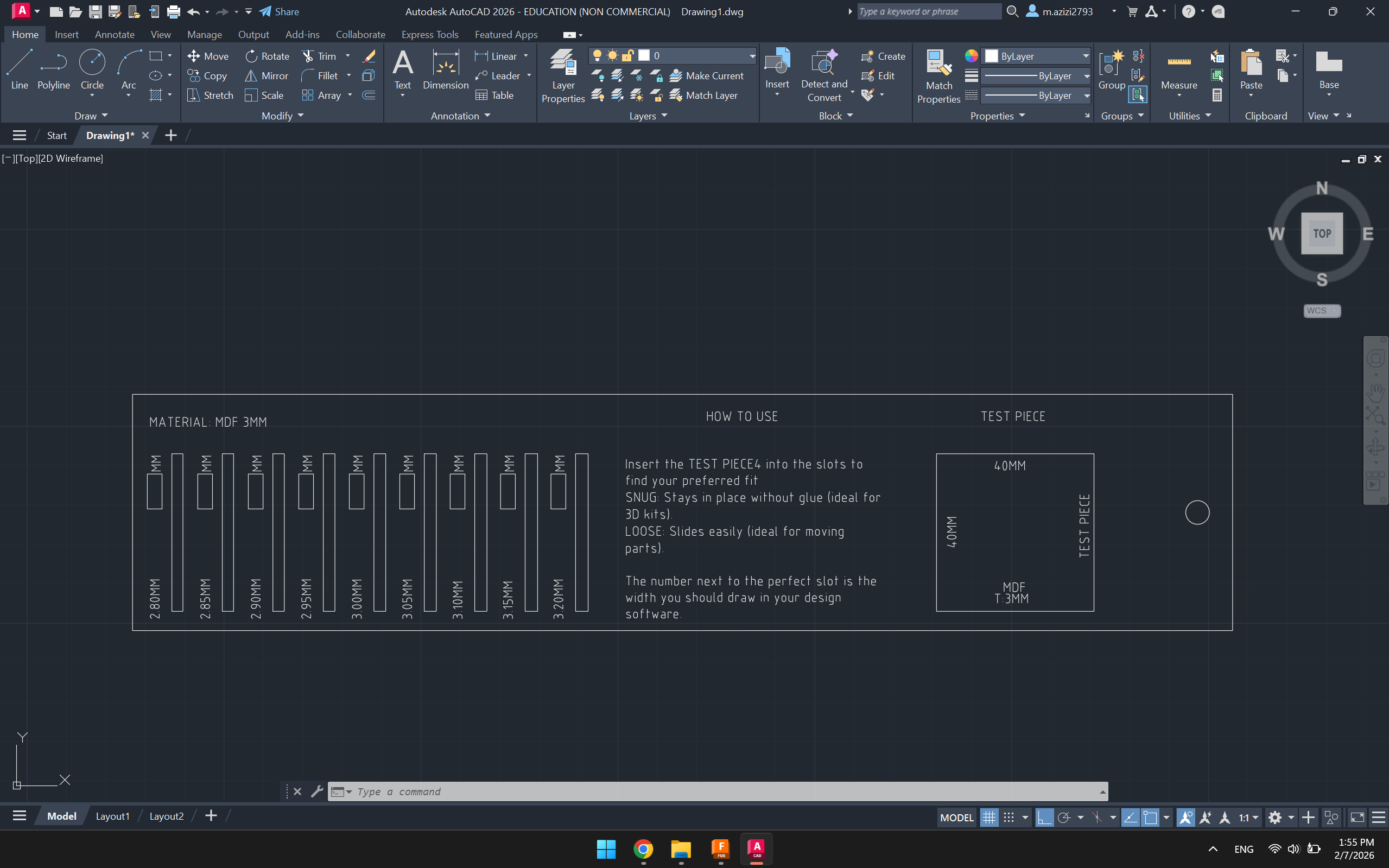
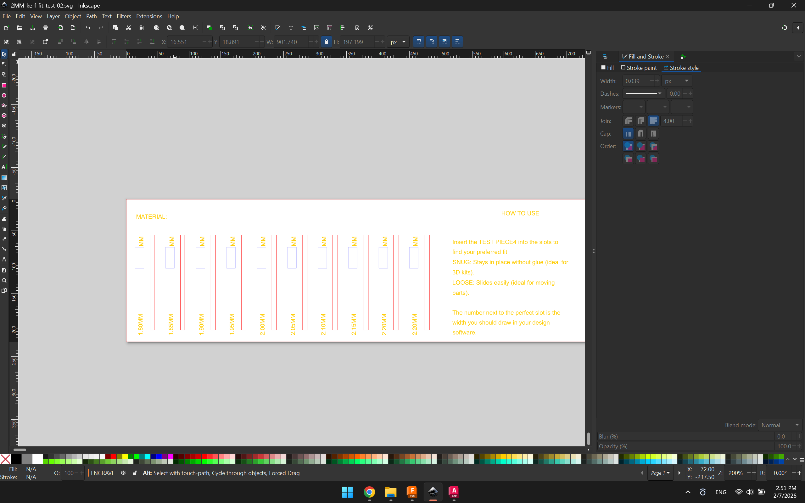
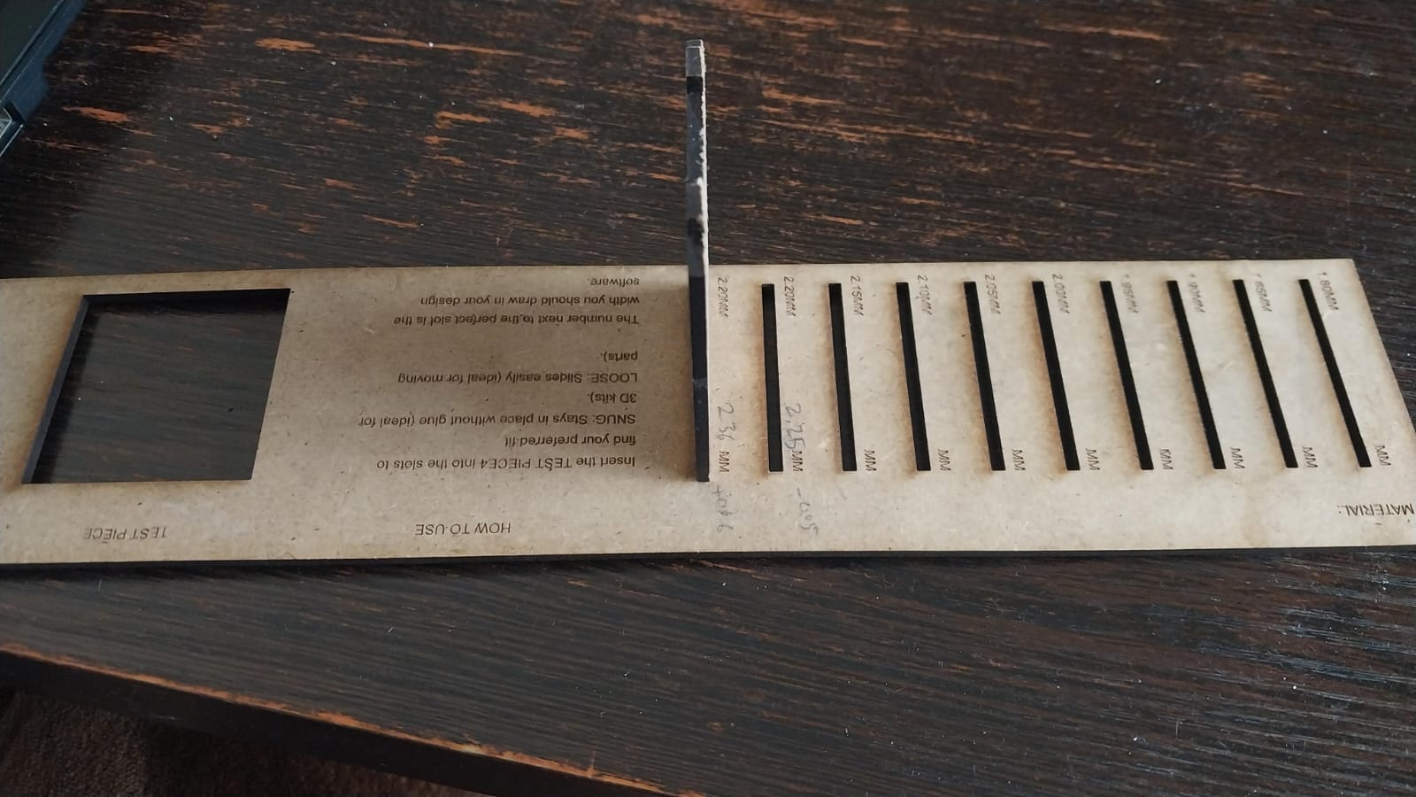
Results
- The kerf value for MDF 2.3 mm was calculated to be approximately 0.06 mm.
- This means that when designing press-fit joints, a clearance of around 0.06 mm should be added to ensure a proper fit after cutting.