Group Assignment
Digital Adjustable Mannequin / Waist Model and Prototype.
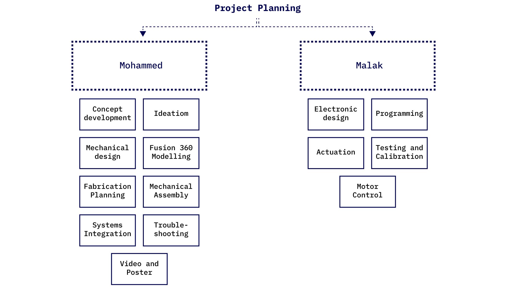
Project Work Breakdown Structure
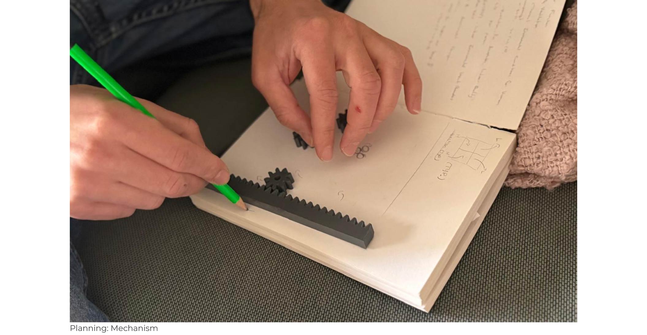
Iniital Sketching to draft the rack and pinion mechanism
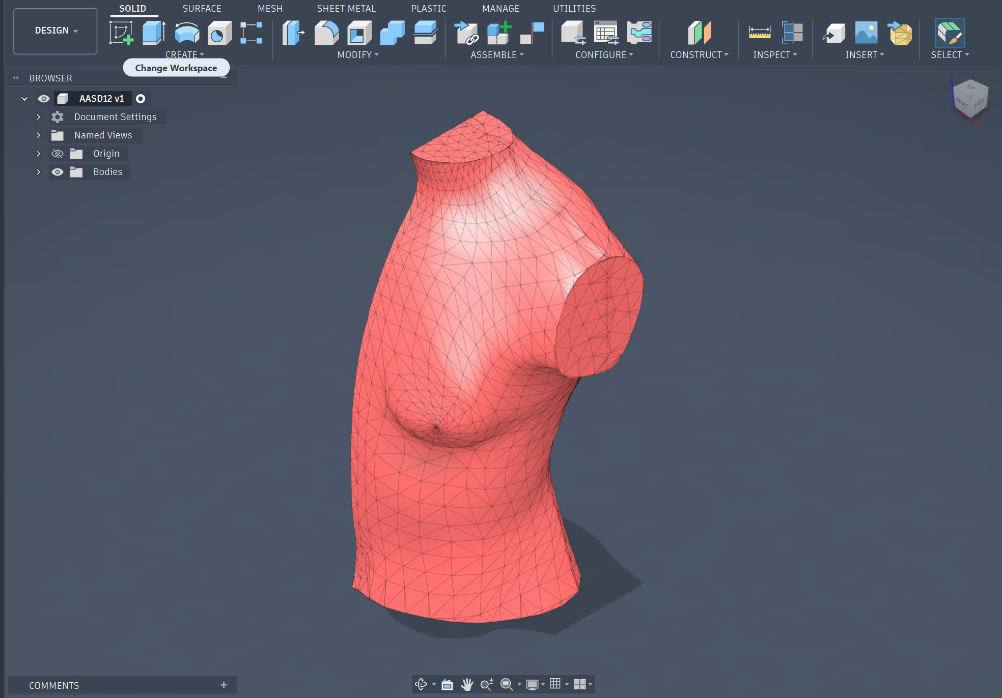
1. Importing the raw MakeHuman torso mesh as a geometric reference base.
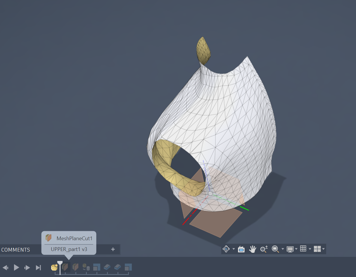
2. Sectioning the mesh with plane cuts to isolate targeted anatomy zones.
3. Reviewing the initial surface patch thickness and orientation from the isolated anatomy section.
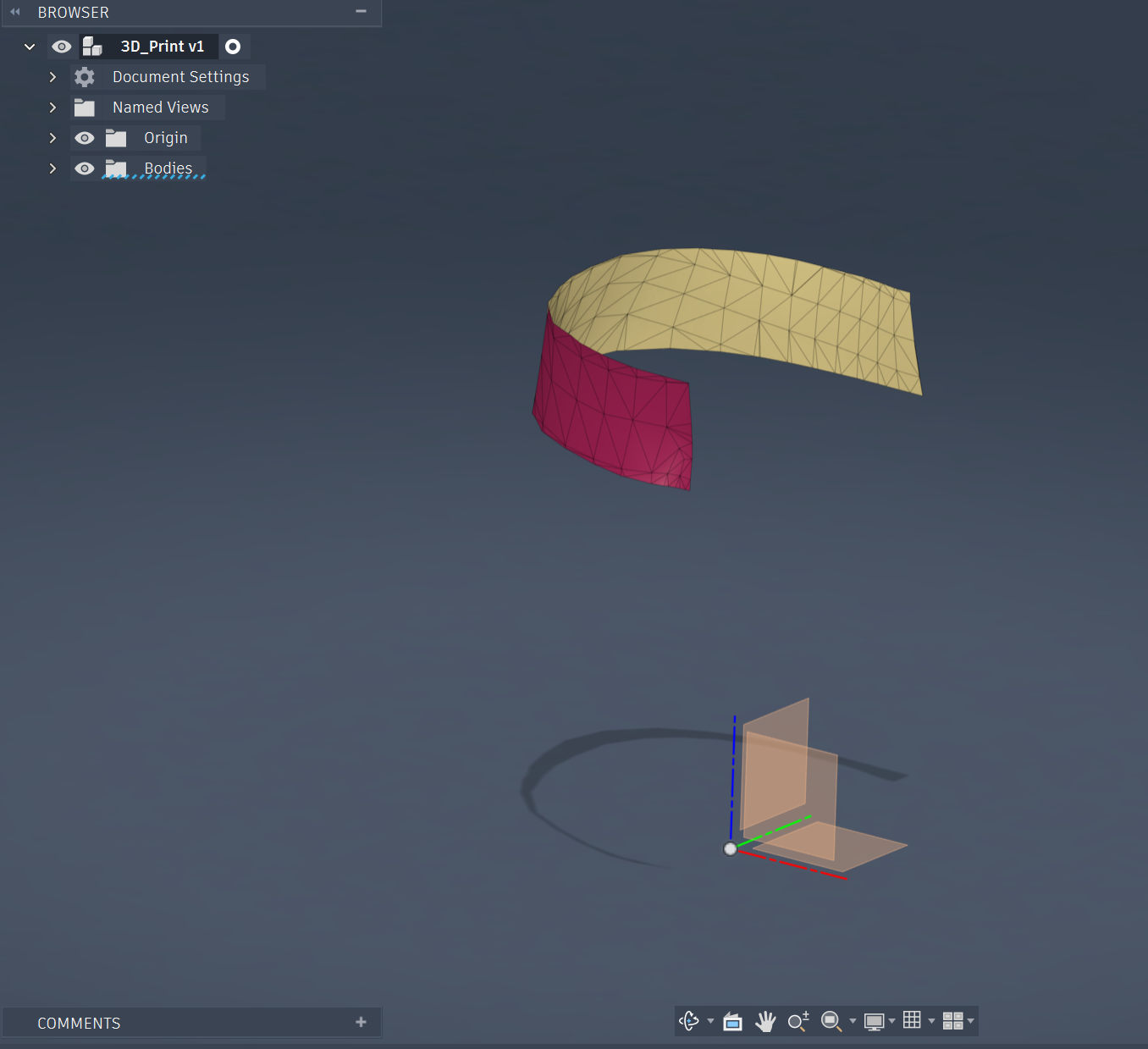
4. Isolating and partitioning specific mesh face strips to trace the shell profile.
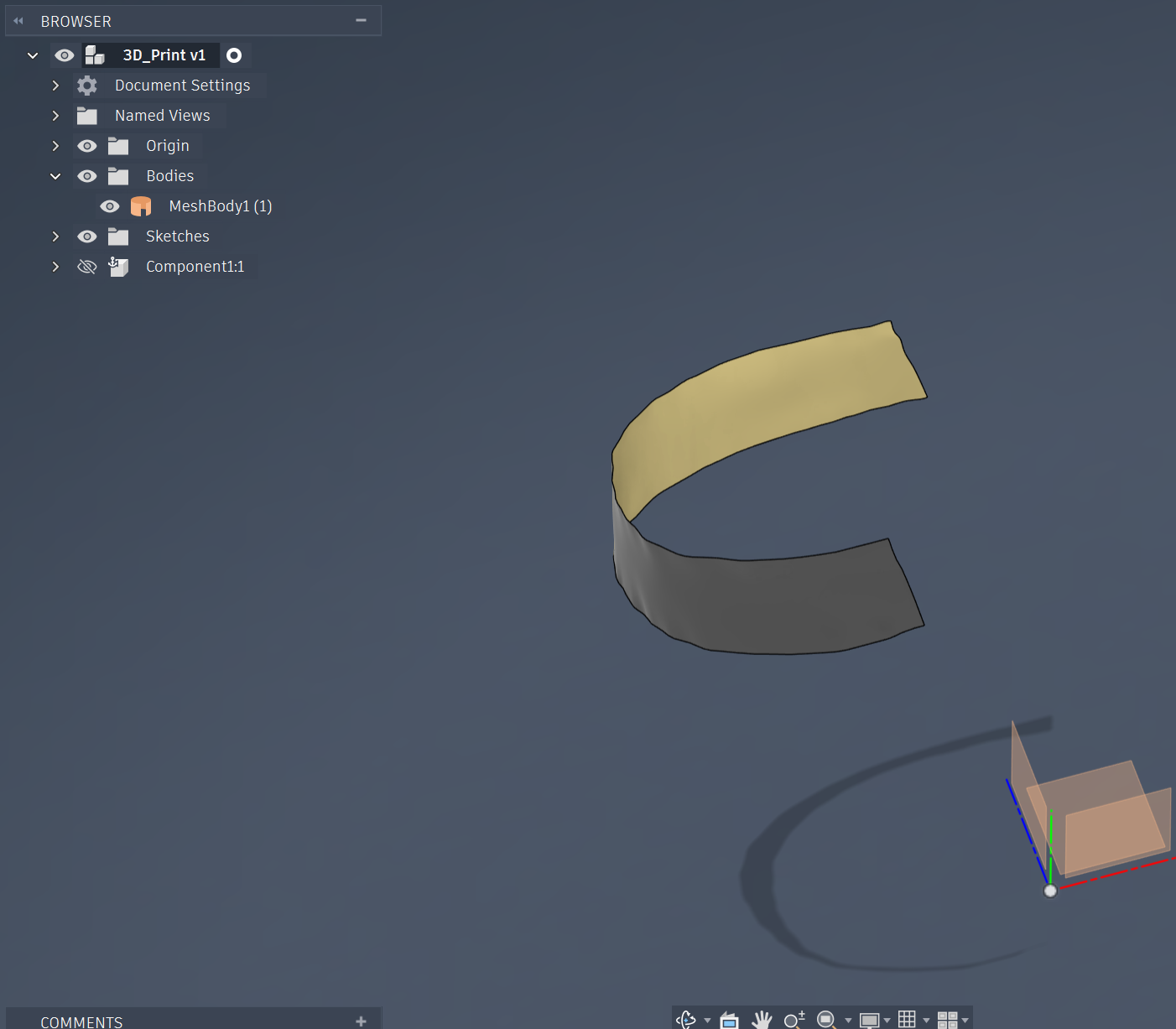
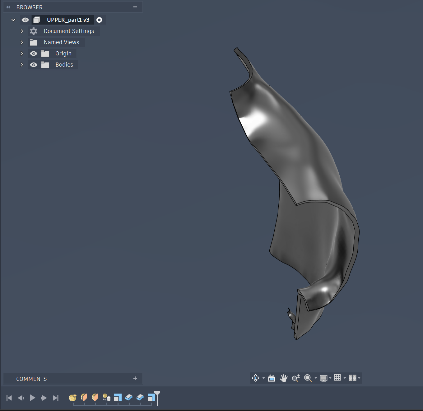
5. Converting the faceted mesh segment into a clean, smooth reference surface.
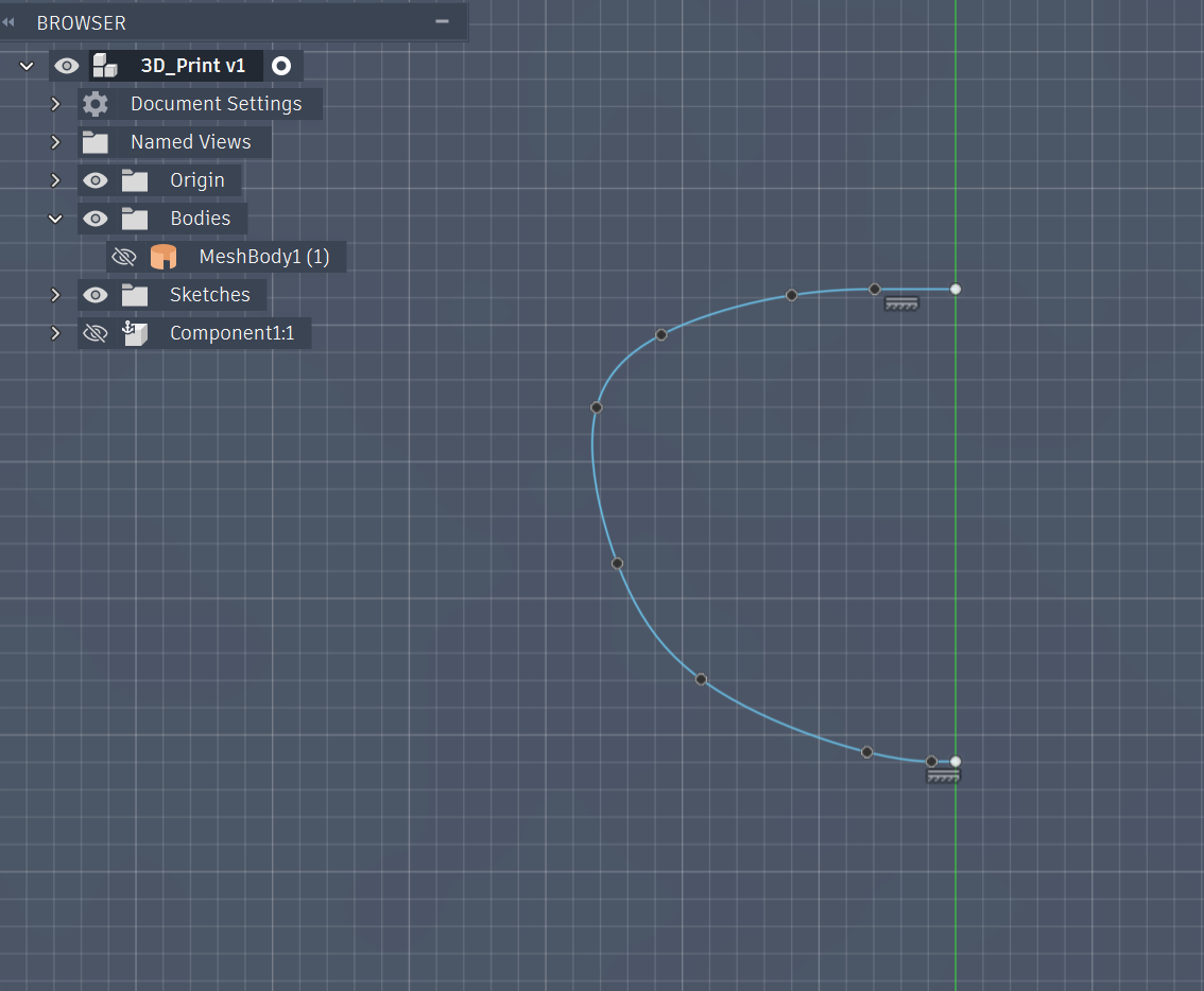
6. Tracing the precise anatomical curvature profile using a 2D spline sketch.
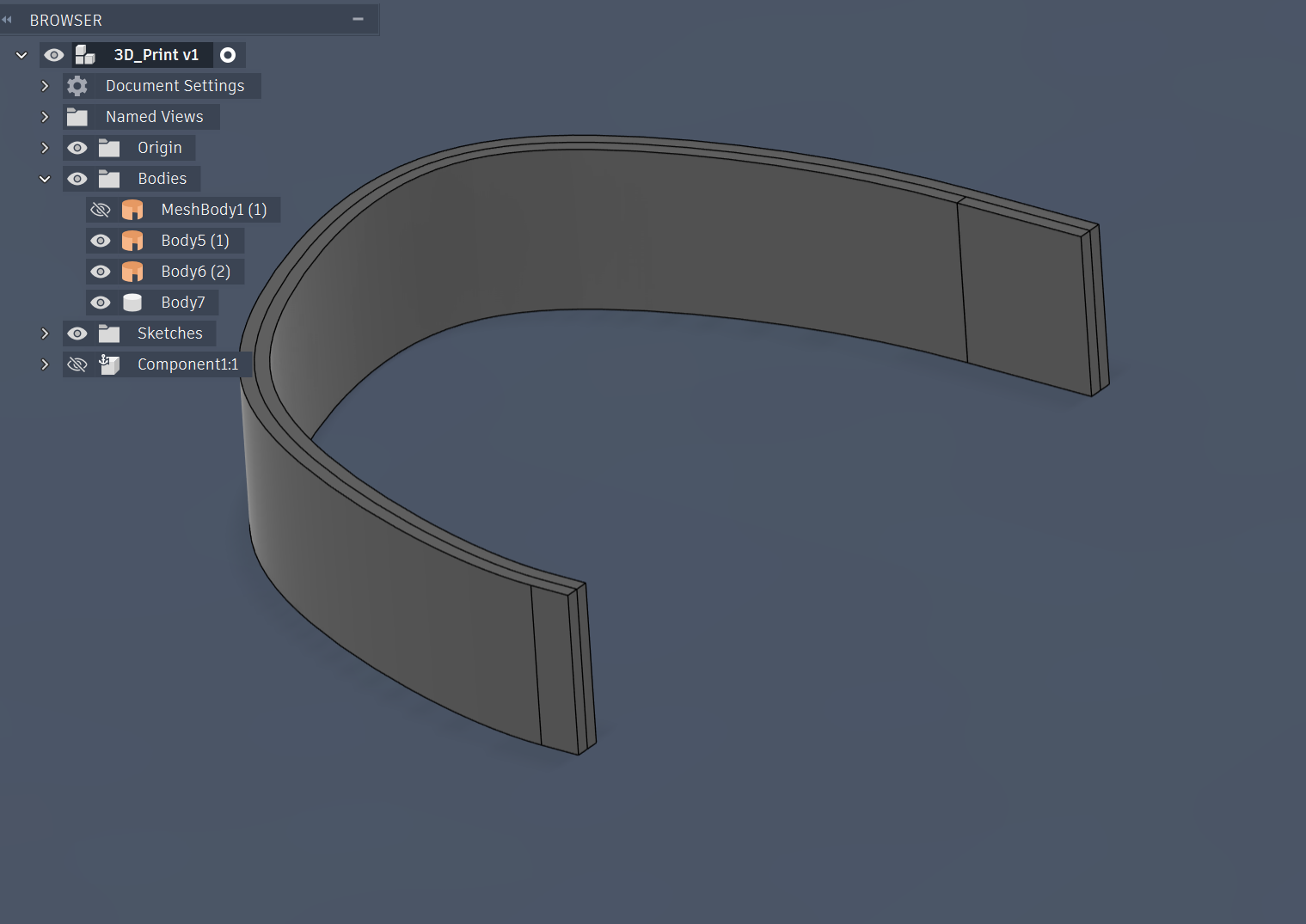
7. Final individual body shell component optimized to mount onto the adjustable mannequin skeleton.
Initial Waist Mechanism Model (Proof of Concept)
Second Waist Mechanism Model (Proof of Concept)
Final Waist Mechanism Model
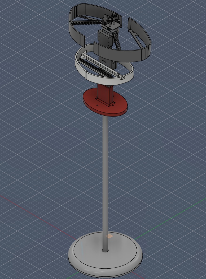
Column Development
Bust Mechanism
Final Design/div>
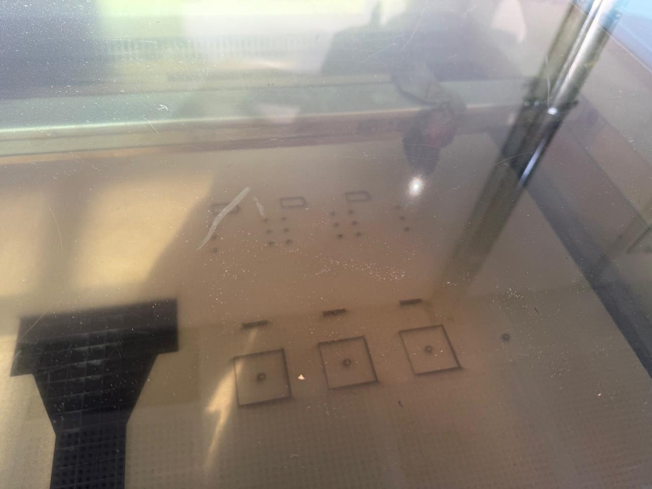
3d Printing the base , Material PLA, 0.4mm layer height/ 0.8 mm nozzle/ ultimaker s5
PLA and PETG / 0.2MM LAYER HEIGHT/ NUMBER OF WALLS 4-5
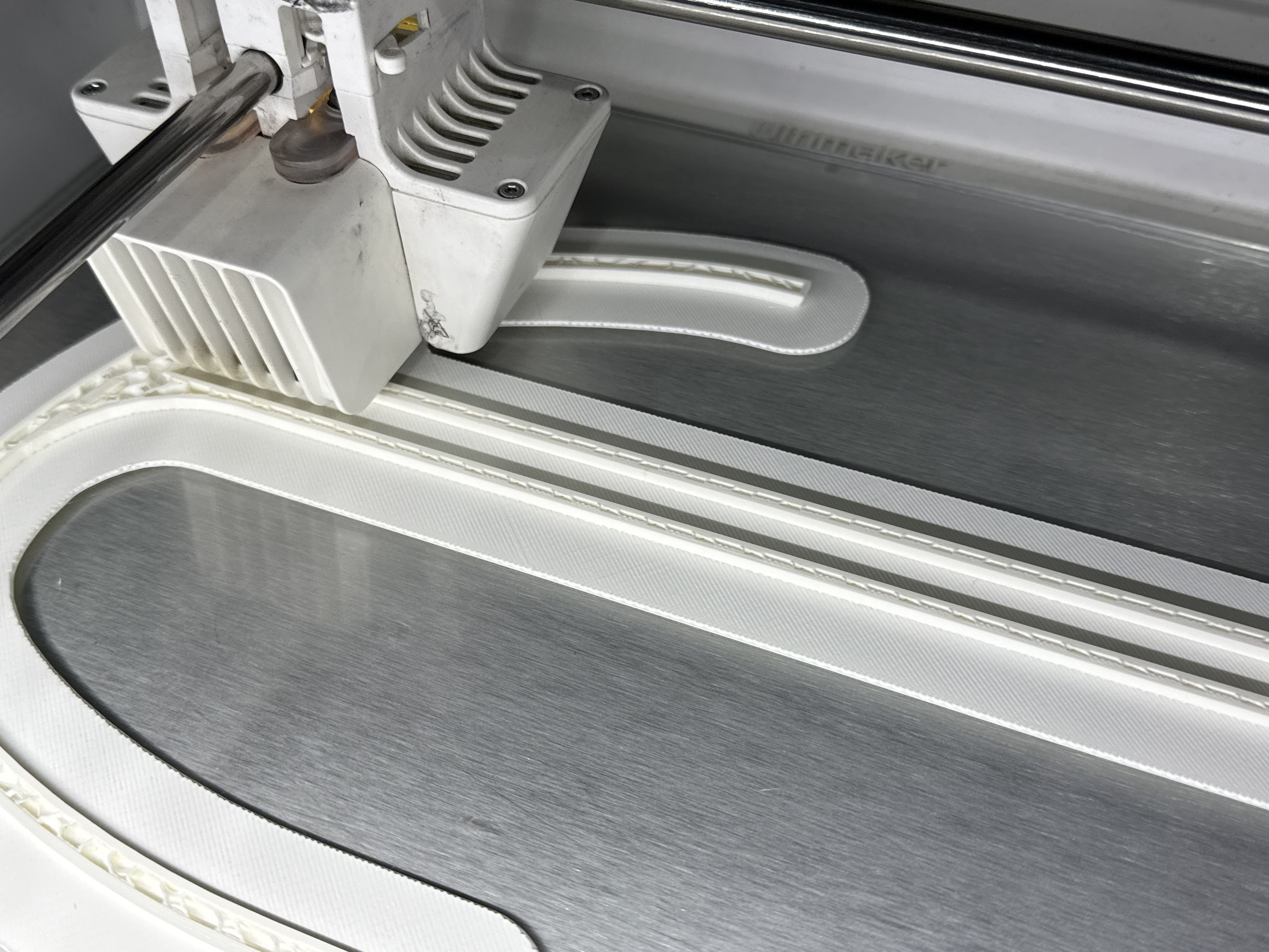
Material PLA, 0.4mm layer height/ 0.8 mm nozzle/ ultimaker s5
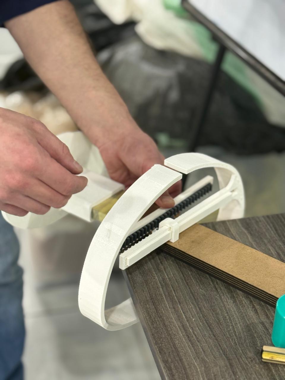
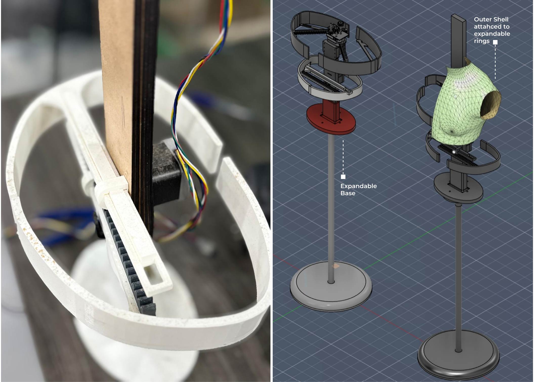
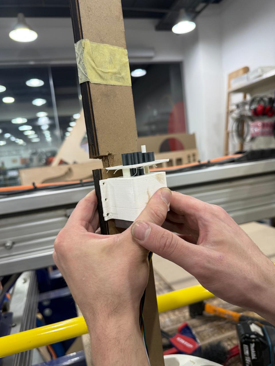
Assembky of the motor and waist mechanism
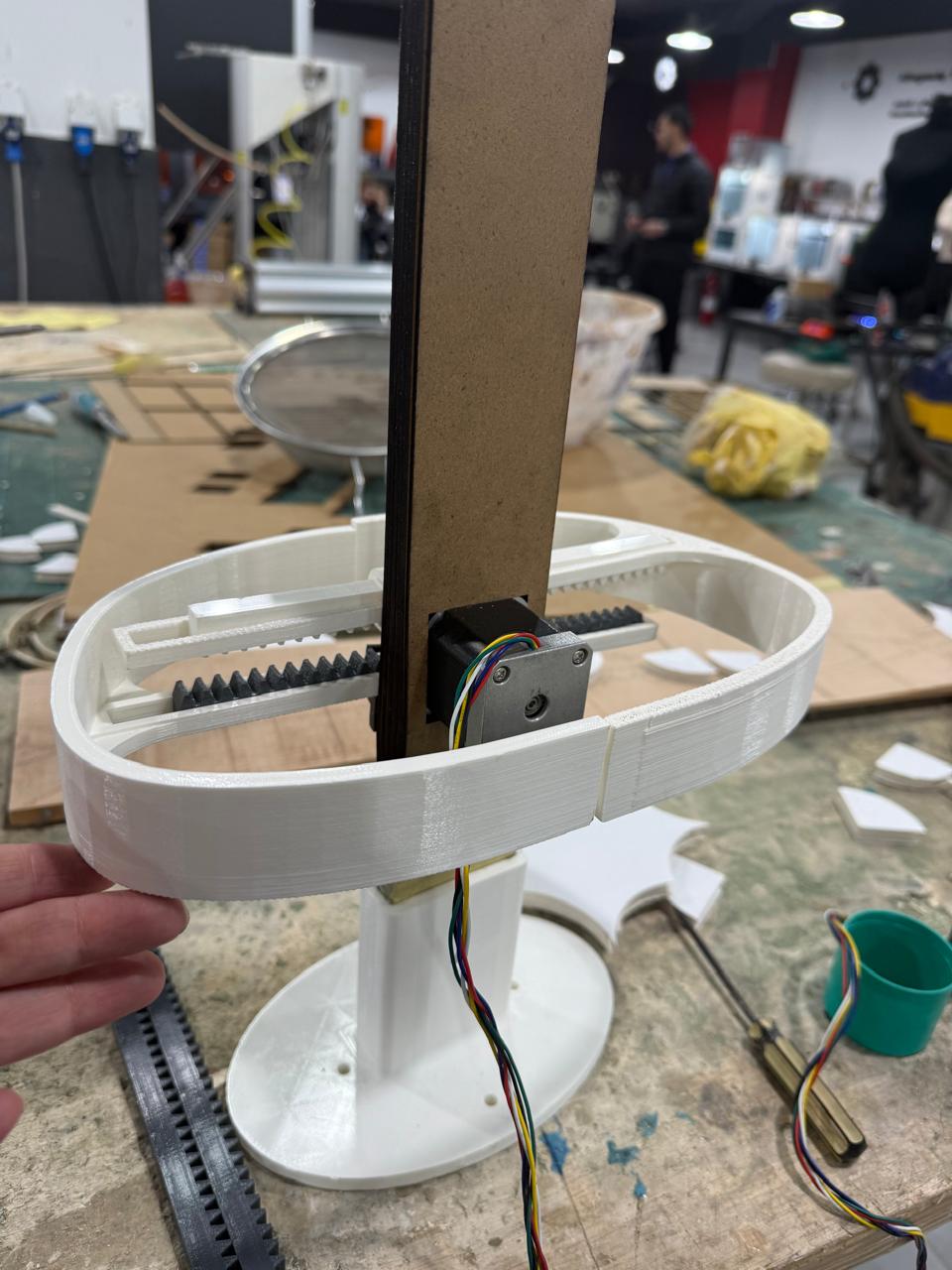
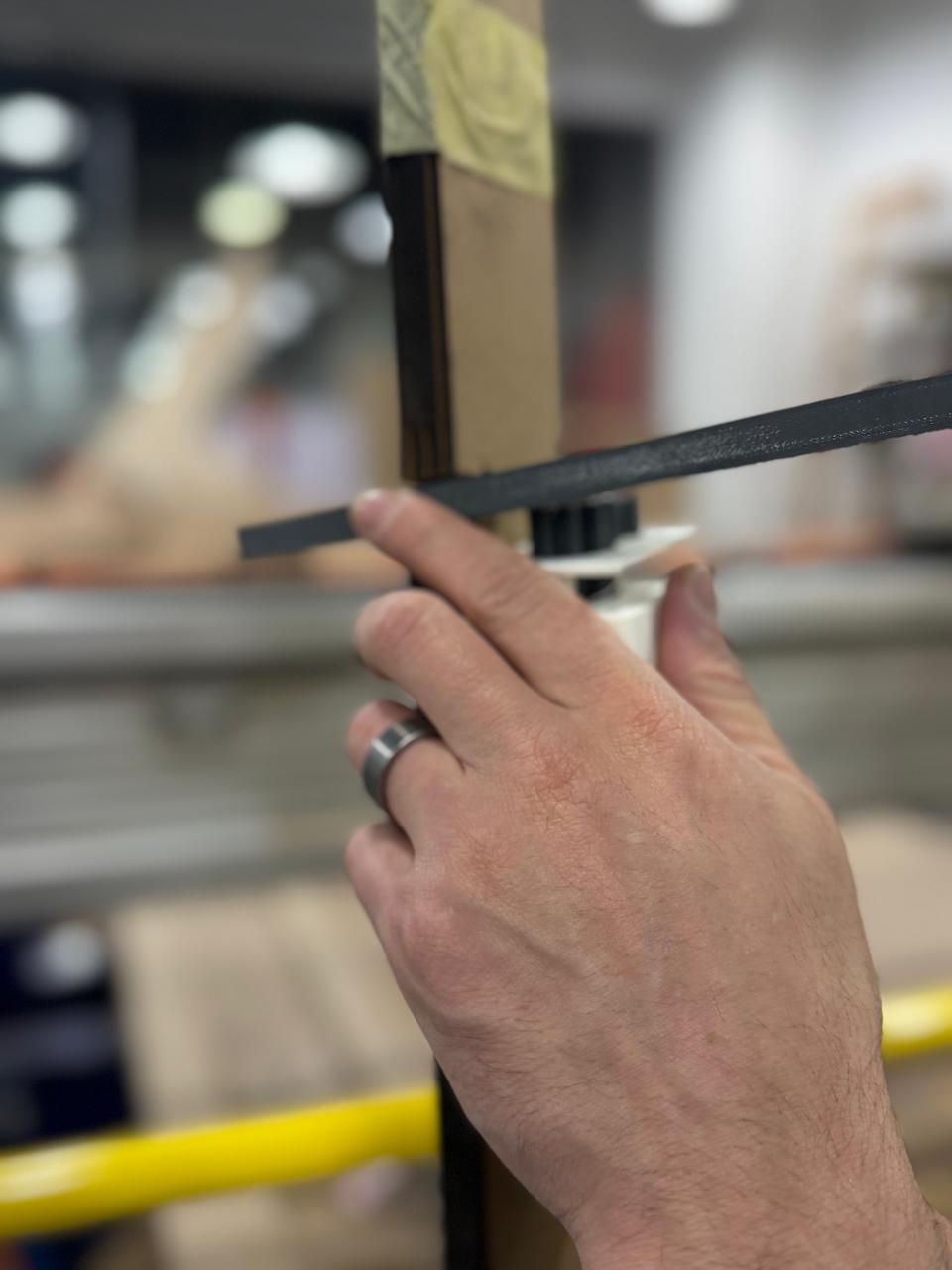
Front view of the waist mechanism
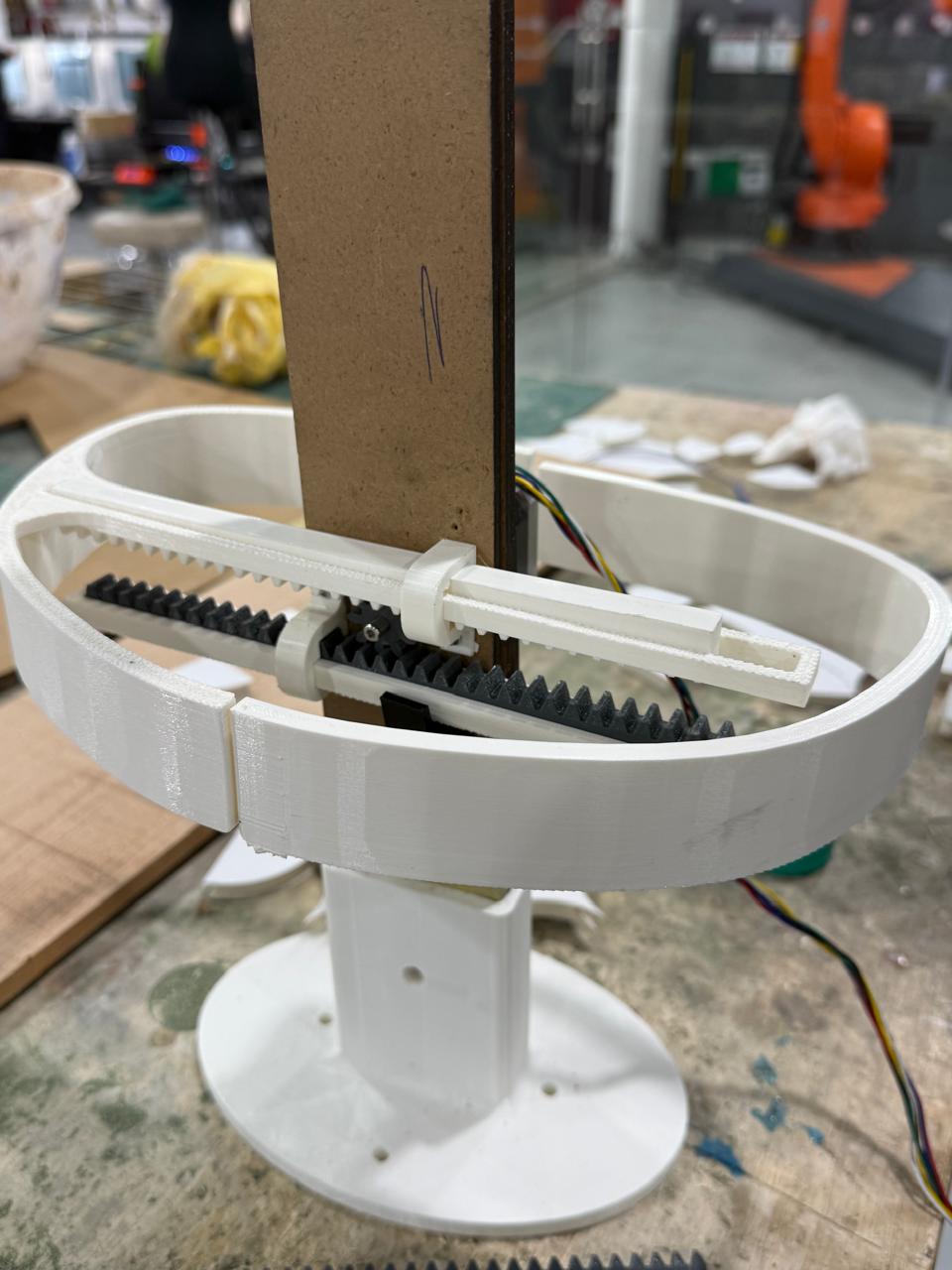
Back view of the waist mechanism
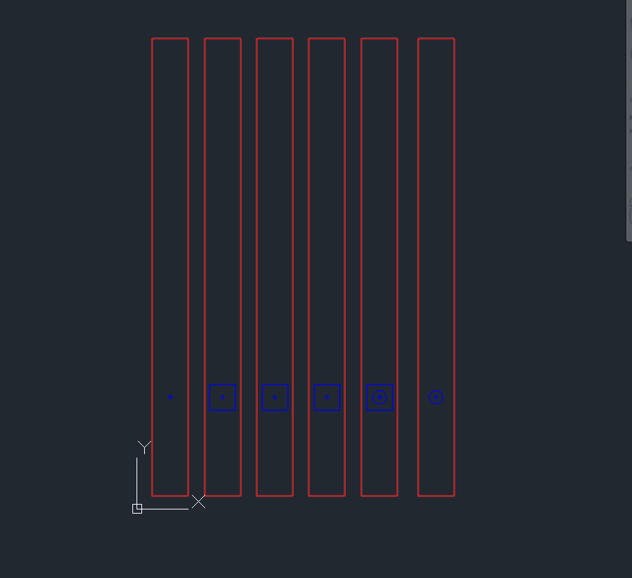
dxf preview of the first version of the long column
dxf preview of the first version of the long column
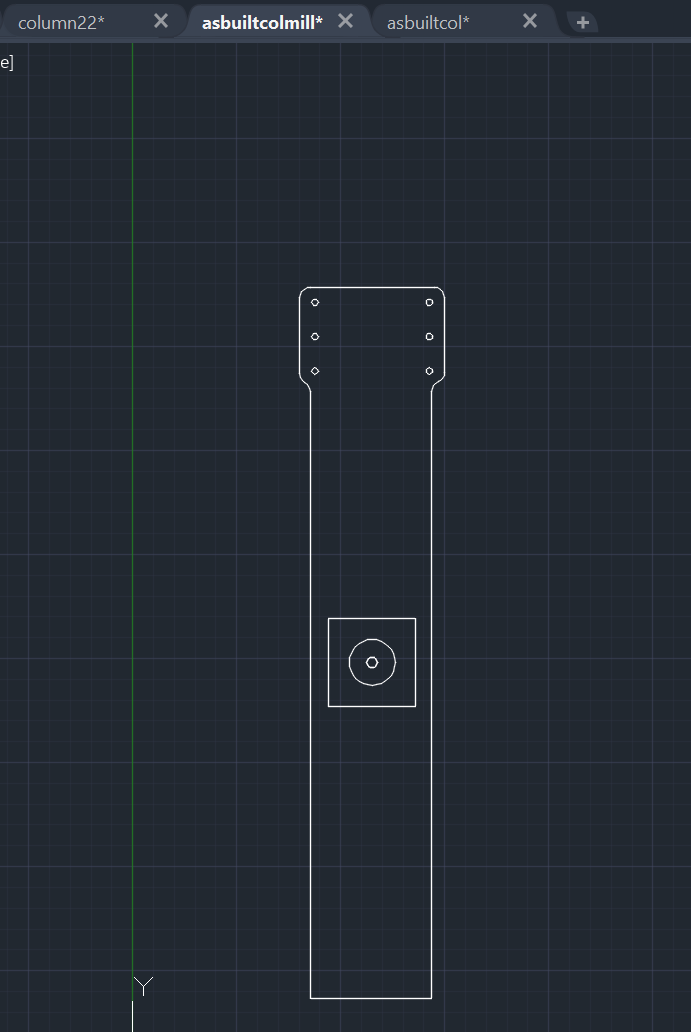
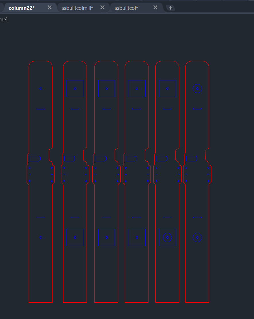
dxf preview of the first version of the as built column
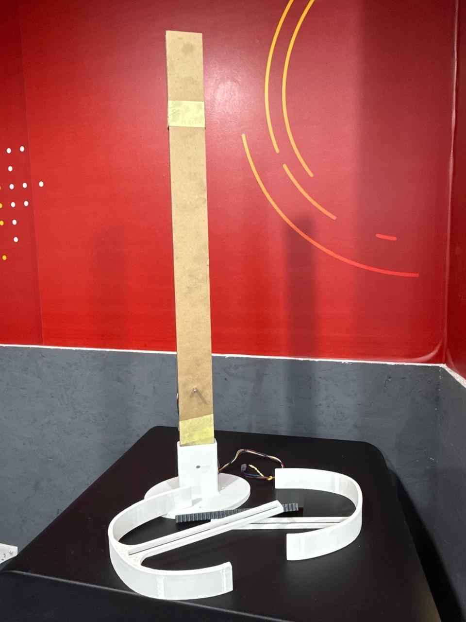
first col assembly
laser cutting second version

mods to first column (as built modifications)
Autodesk fusion plugins
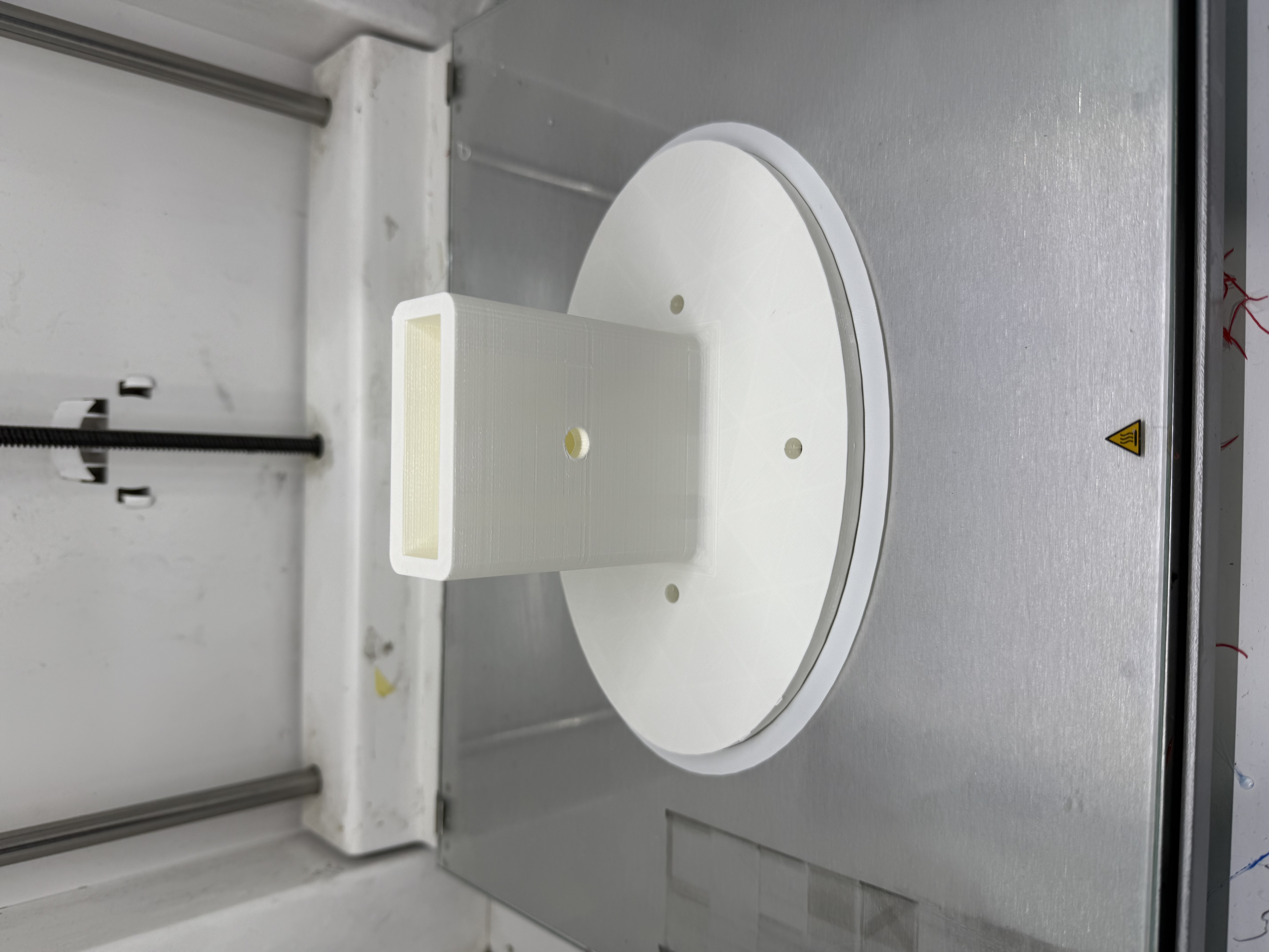
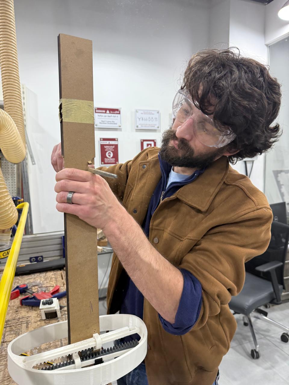
The second phase was manufacturing the bust mechanism,as mentioned earlier my first iteration for this failed but this phase was a mix of live modifications and reflecting the outcomes on
the model, below area few shots of this "Failed" phase which led to me to develope the radial expansion mechanism later on. this phase also covered the 3d printing of the motor vertical clamp base
which remained unchanged during the project.
I used GF Gear Generator plugin to model my racks and gears , the parameters i had are:
- Module (m): 1 mm
- Number of teeth (z): 9
- Pressure angle: 20°
- Pitch diameter: 20 mm
- Tip (addendum) diameter: 22 mm
- Root (dedendum) diameter: 17.5 mm
- Addendum: 1 mm
- Dedendum: 1.25 mm
- Clearance: 0.25 mm
- Face width: 10 mm
- Bore diameter: ~4.95 mm
- Hub OD: ~13 mm
- Total part length: 42.9 mm
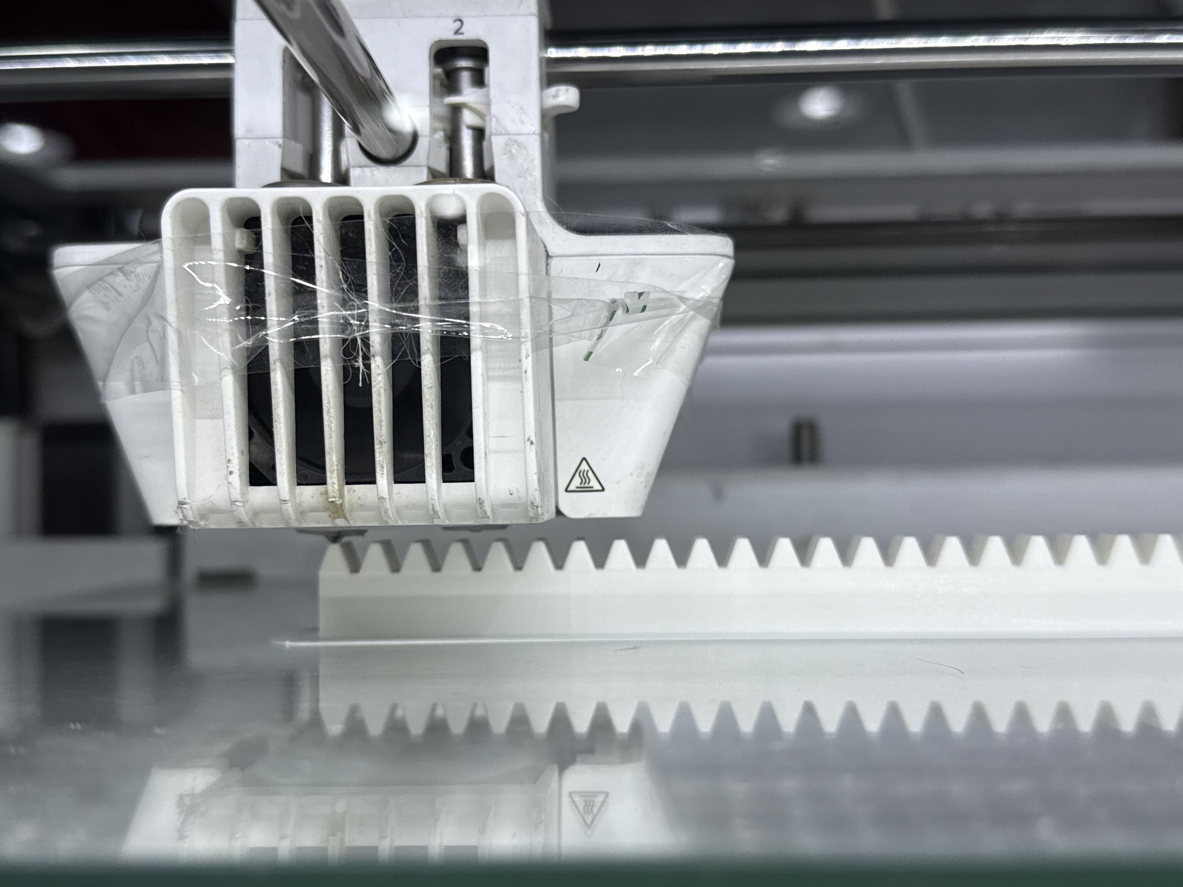
Matching Rack (GF Gear Generator)
- Module: 1 mm
- Pressure angle: 20°
- Addendum height: 1 mm
- Dedendum depth: 1.25 mm
- Tooth pitch: π × m ≈ 3.1416 mm
- Face width: ≥ 10 mm
- Fillet radius: 0.38 mm
- Number of teeth: as required by travel distance
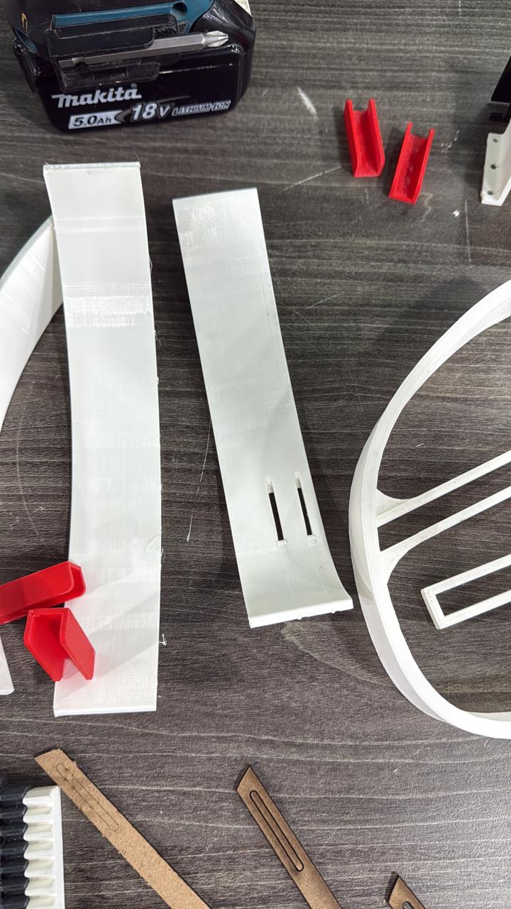
I 3d printed the front bust pieces alongside with red "guides" and holders
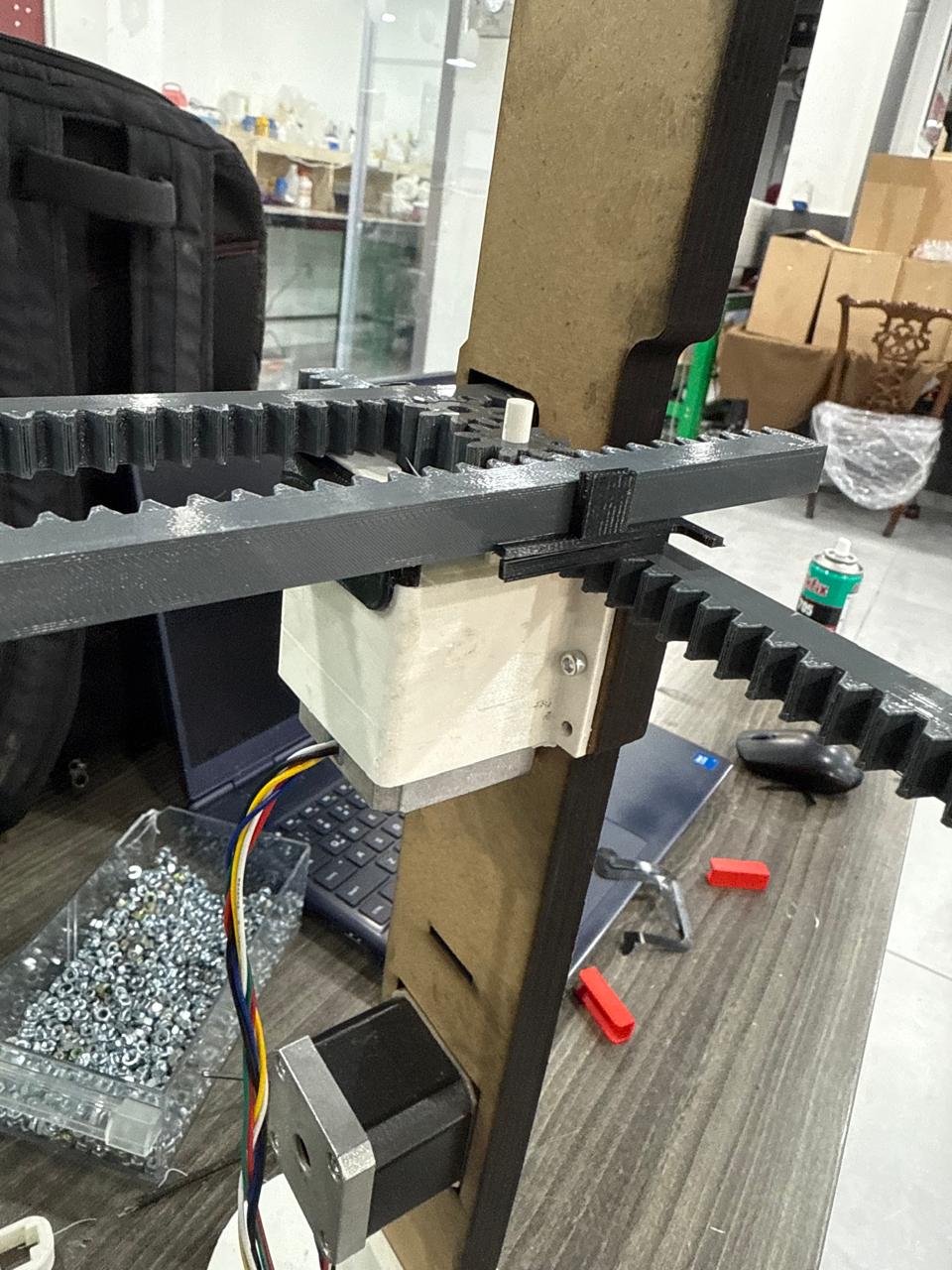
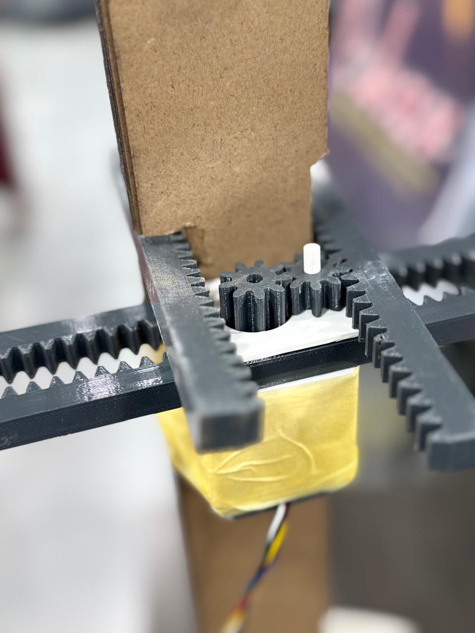
Here I did the assembly and you can see the open slots in the second column version what they served, in addition to some on the spot plates to hold the gear mechansim on top of the motor
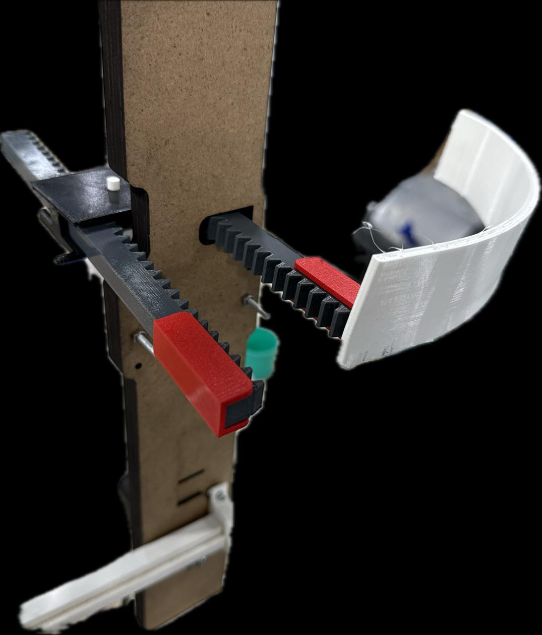
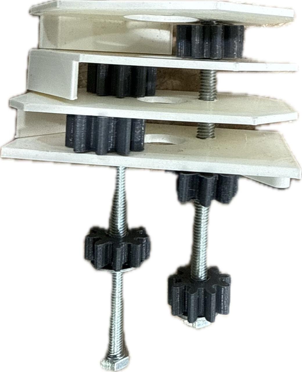
Back view of the mechanism, the actuated gear rotates clockwise and the second gear also rotates in the same direction,ensurign both racks push outwards/inwards at the same time, the failure is this is only good if we only had front pieces for the bust,not 4
failing to realize this observtion earlier i proceeded and modified the gear to become longer here and created the first "two level" rack and pinion mechansim, the long gear turns to isolated top and bottom motion gears responsible
for the top and bottom racks
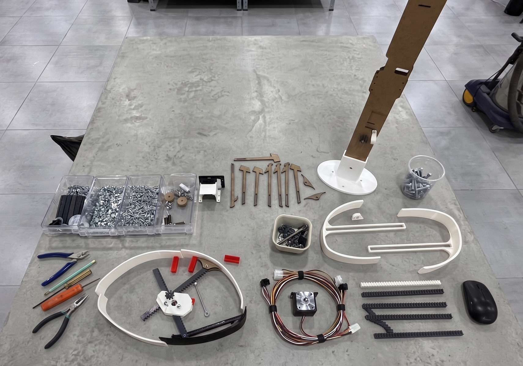
Final Part List
The Final Pivot:
During a final development sprint, I redesigned the mechanism into a
Spider Radial Expansion system. This utilizes a multilayered rack and pinion mechanism for much higher reliability.
This was the major issue I faced during the design of this project, below is a progress of the the first bust mechanism was and the final design sketch I
developed.
This was one of the most major problems and iterations I had to work around with to acheive linear motion expansion movement for the bust