Week 3: Computer-Controlled Cutting: Laser Cutting
💡 Note: You can download the project files here.
1. Idea
This week I wanted to create an assignment I could be proud of, so I decided to make a car from 3 mm MDF.
2. Design
- Select a reference image
- Generate a 3D model
- Prepare parameters
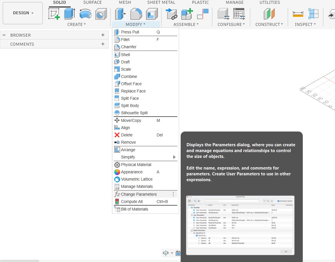
- Go to the "Modify" menu and select "Change Parameters".
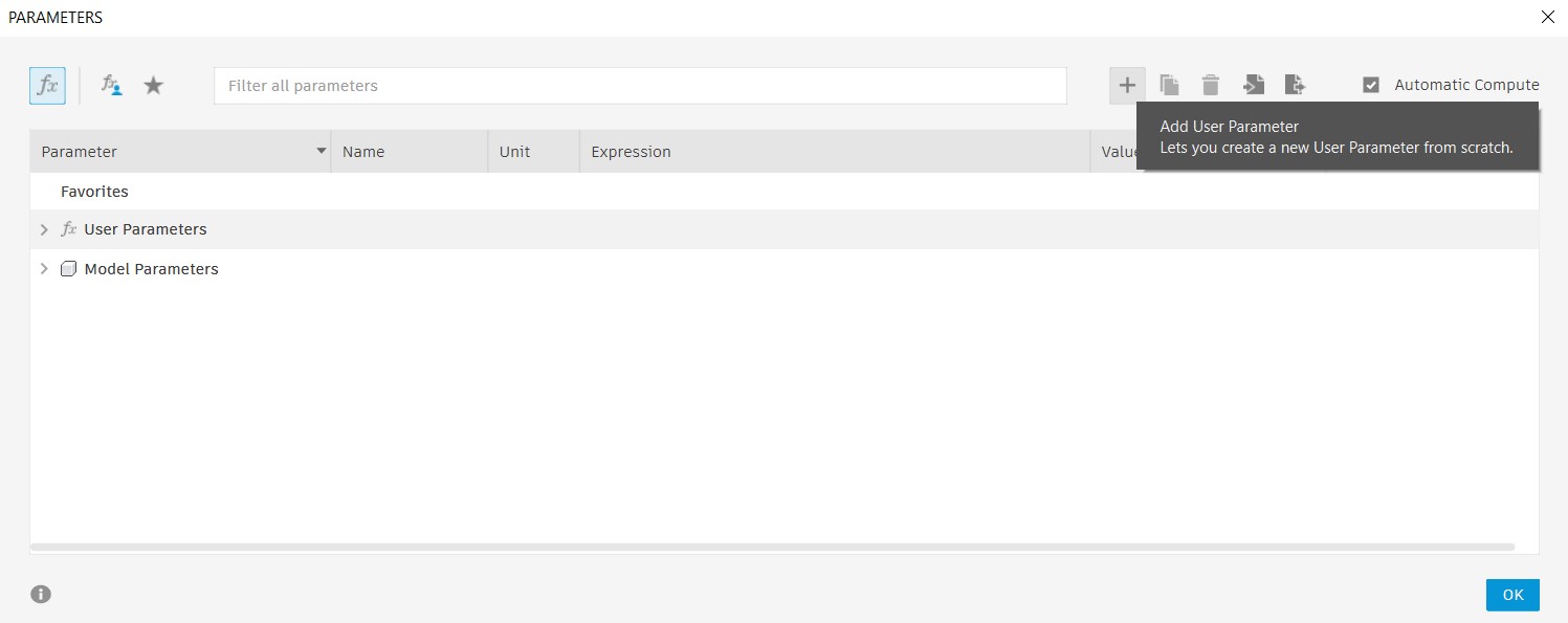
- In the Parameters dialog box, click on the "+" button to create a new parameter.
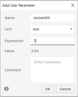
- Give your parameter a name (e.g., "SlotWidth") and set its value (e.g., 3 mm).
- Click "OK" to save the parameter.
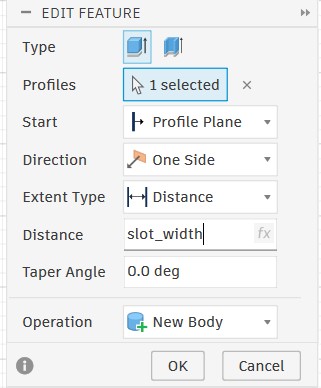
- Now, to use the parameter in your design, simply type the parameter name (e.g., "SlotWidth") in any dimension field instead of a specific value. This way, if you need to change the slot width later, you can just update the parameter value, and all dimensions that use that parameter will automatically update accordingly.
- Drawing the 3D model
I did not have exact dimensions for the car, so I chose this photo from the internet as a reference.
The 2D reference image was not sufficient to determine exact dimensions, so I created a 3D model based on it. I used Meshy AI, which temporarily offered free downloads of models generated by the Meshy 4 AI model.
Here is the 3D model generated by Meshy AI.
Before modeling, I set up parameters to make the design parametric. Below is how to define and use parameters in Fusion 360.
I used Fusion 360 to model the car and generate 2D drawings for each part.
Here is the 3D model from Fusion 360.
3. Prepare model for cutting
I converted the model from 3D to 2D by projecting it onto planes to create cutting paths, then combined the projections into a single file for cutting.
💡 Note: I initially used Inkscape to create the 2D drawing and set colors for the Trotec laser, but import issues occurred. Switching to Rhino resolved the problem and made color management easier.
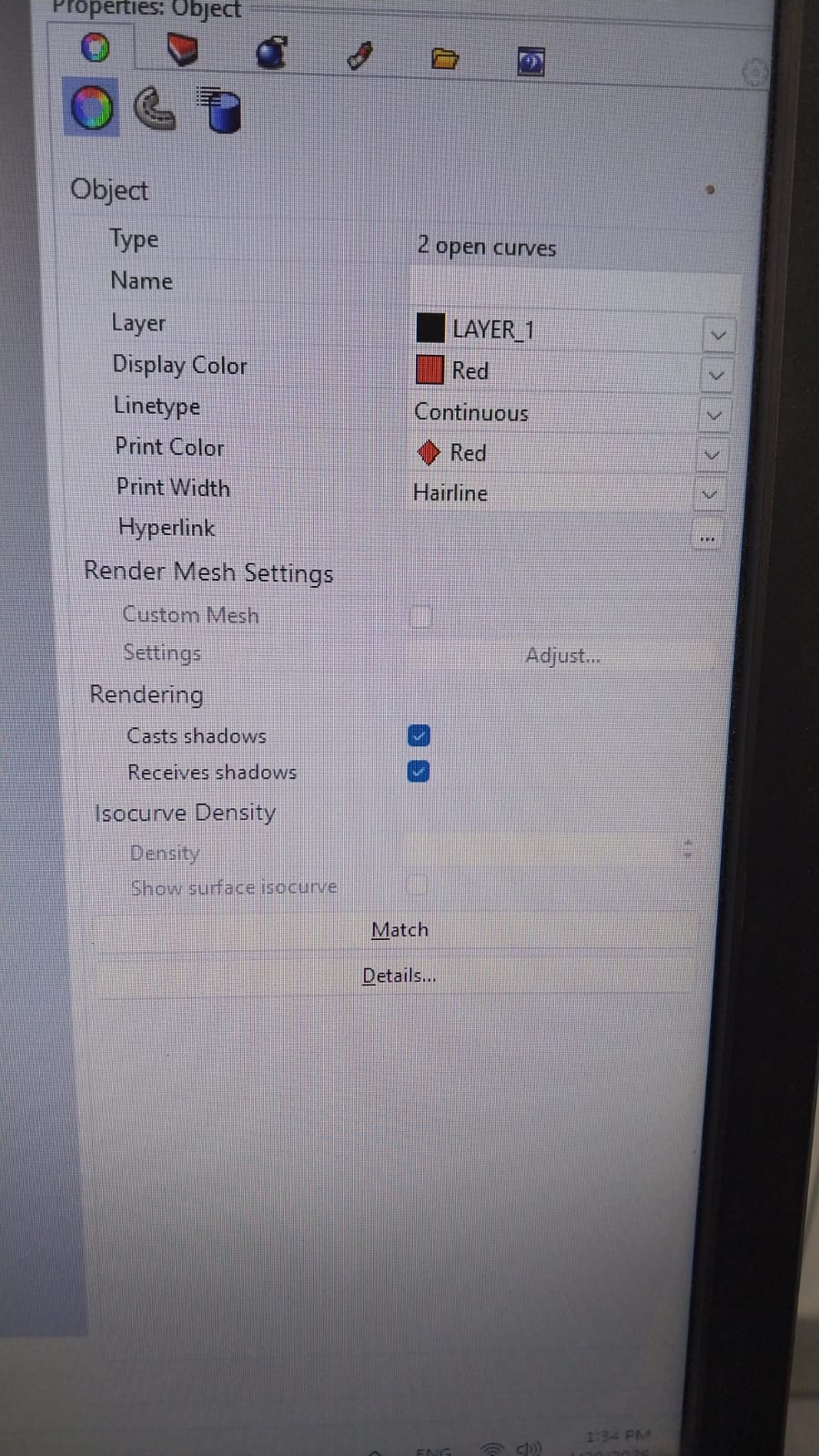
In Rhino, I changed the edge line color to green for cutting and red for engraving, set the linetype to Continuous, and made sure the print width was set to Hairline.
I then imported the 2D drawings into the Trotec software for laser cutting.
4. Cutting process
I used the Trotec laser cutter to cut the car parts from 3 mm MDF.
Here are the settings I used for cutting 3 mm MDF.
- Power: 70%
- Speed: 0.4
- Z Offset: 0
I made a test cut for the slots to verify dimensions and fit.
Here is the cutting process.
After testing, I determined the kerf should be 0.25 mm and applied this to the model. I updated the design based on test results so all parts fit together. With parametric design, I adjusted slot dimensions by changing a single parameter. Below is the parameter list.
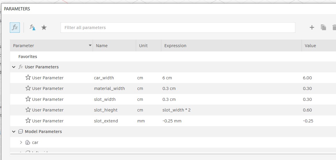
💡 Note: The kerf value produced here as a slot_extend value which is 0.25mm .