Final Project: Car Side Mirror Theft Alarm System

Project Overview
This project focuses on developing a car side mirror theft alarm system that detects unauthorized removal or tampering of a vehicle’s side mirror and triggers an alert.
The system uses a Hall effect sensor and magnet pair to monitor the presence of the mirror. When the mirror is detached, the magnetic field is disrupted, and the system activates an alarm.
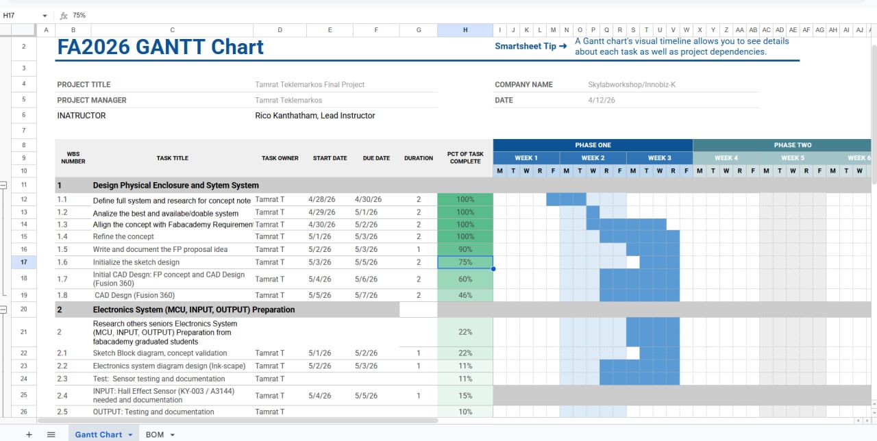
Project Planning
System Concept
Working Principle
- A magnet is attached to the mirror housing.
- A Hall effect sensor (KY-003) is fixed to the car body.
- When the mirror is in place → magnetic field detected.
- When removed → magnetic field lost → alarm triggered.

- This project presents a digitally fabricated anti-theft system designed to protect car side mirrors from unauthorized removal.
- The system operates by detecting the presence of a magnetic field using a Hall effect sensor. When the mirror is detached, the magnetic field disappears and an alarm is triggered.
- The development follows the Fab Academy workflow, combining 3D design, electronics production, CNC milling, and vinyl cutting into a single integrated system.
What does it do?
TI tried to made a system continuously monitors whether the car side mirror is attached or removed. A magnet is fixed to the mirror box, while a Hall effect sensor is placed on the car body (or vice verse… since both scenario works). As long as the mirror is in position, the magnetic field is detected and the system remains inactive.
Once the mirror is removed, the absence of the magnetic field is immediately detected, and the system activates an alarm through a buzzer and LED indicator.
Workability and current trend of cars security
A I see as possible research the existing automotive alarm systems typically focus on door access, vibration sensing, or motion detection on the whole body. However, specific detachable parts like a side mirror and charging port is a common vulnerable issue that is not specifically addressed in most systems of cars.
Scope of the project
I designed to solve local problem in my city. To save the vulnerable cars part not easily stolen and theft gone away with those parts together. The project involved designing both the electronic and mechanical aspects of the system, as well as integrating them into a working prototype.
On the electronics side, a custom circuit will be developed to interface the Hall effect sensor with an ESP32 XIAO C3/RP2040 MCU, which processes the signal and controls the alarm outputs.
On the mechanical side, several custom parts will be created, including a PCB holders that fits onto the mirror, and an enclosure that protects the electronics and optionally car mirror holder (Imitation). These parts were designed to ensure proper alignment, durability, and ease of installation and testing.
For my cars part theft alarming the following materials and components will be used
The electronic system which is based on an ESP32 micro controller, which provides sufficient processing capability and flexibility for future expansion. A KY-003 Hall effect sensor is used to detect the magnetic field, Magnet to give signal to the hall effect sensor while an active buzzer and LED and car side mirror holders (optionally) provide audible and visual feedback when an alarm condition is triggered.
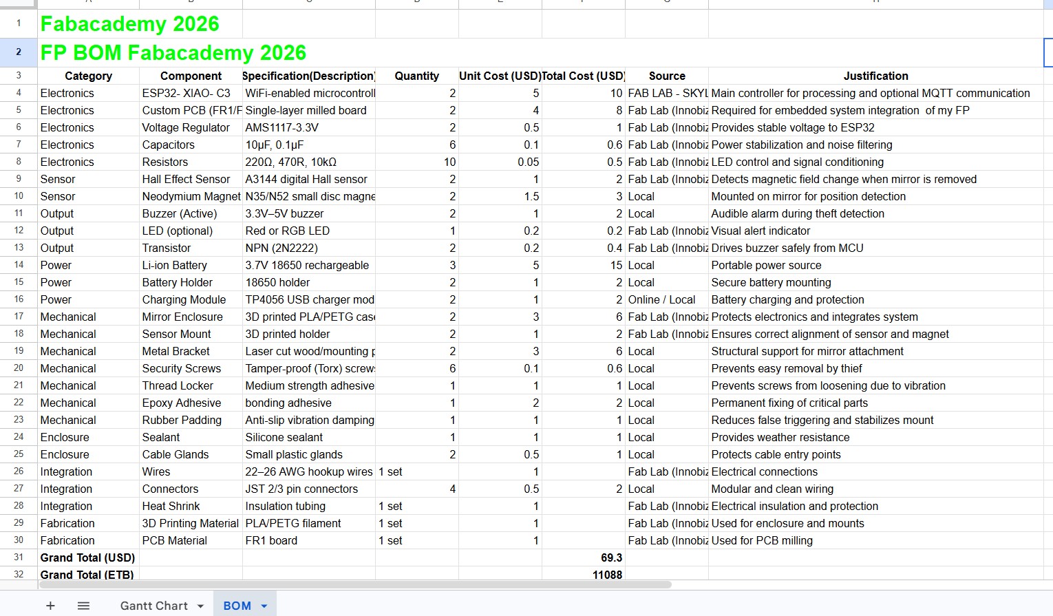
Power is supplied using a rechargeable lithium-ion battery, supported by an appropriate charging module.
Mechanically, I will use both SLA Resin or PLA filament for 3D printing the enclosure and mounting parts.
My ‘MVP’
- The project combines multiple digital fabrication techniques to made my minimum viable product, MVP.
- The mechanical components were first designed in CAD using Fusion 360 and FreeCAD.
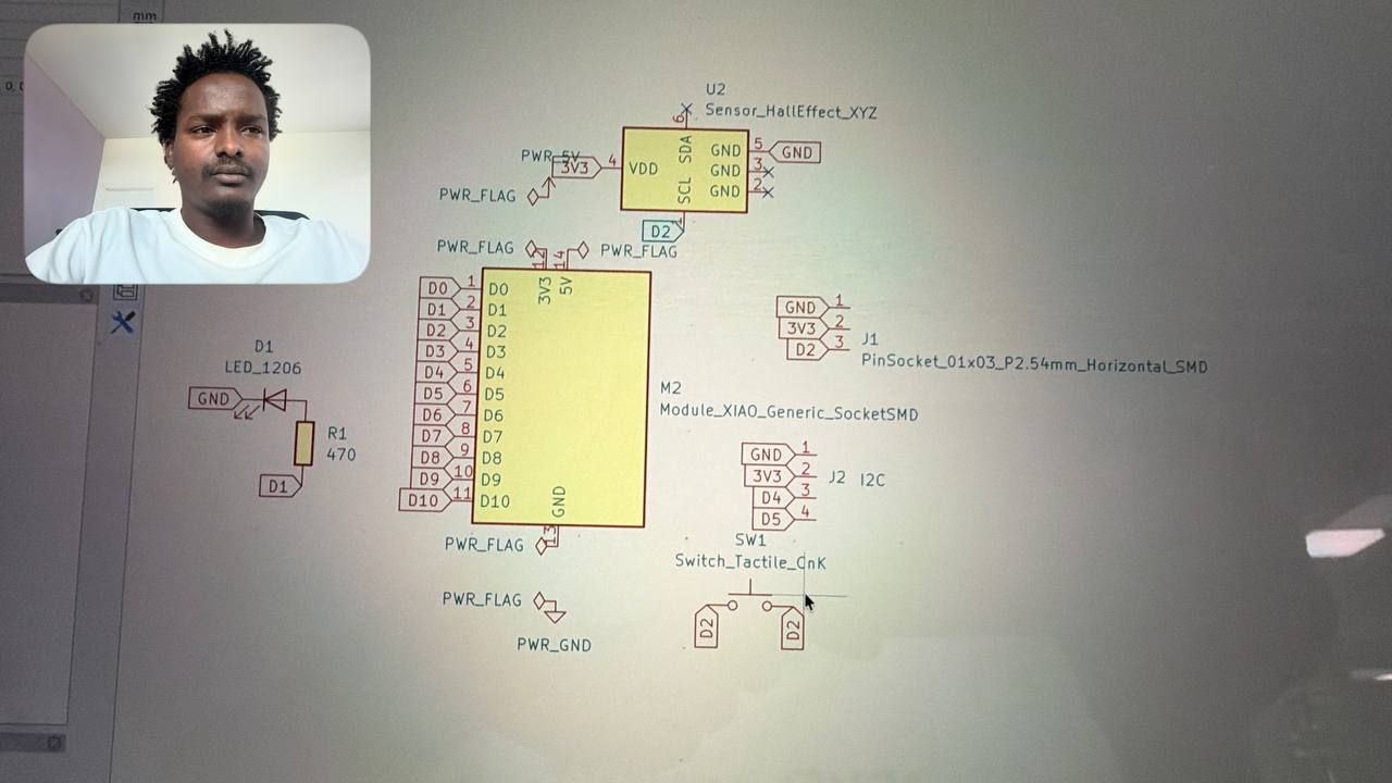
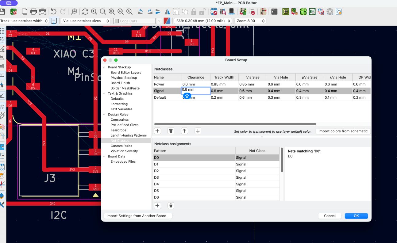
- The electronic circuit was designed in KiCad.
In my FP i will use the FabLab processes
- This project integrates several core Fab Lab processes into a single workflow.
- The design phase involved creating both 3D models and electronic schematics using professional CAD and EDA tools.
- The PCB fabrication process used FR4 material and a CNC router to produce the circuit board.
My progress to th Final Project
The core detection mechanism proved to be reliable once the correct alignment between the sensor and magnet on the board designed as follow. The system responds quickly to mirror removal and consistently triggers the alarm without delay, then size of PCB is matter here and plan in the future work as custom needs
Design version of PCB so far i did
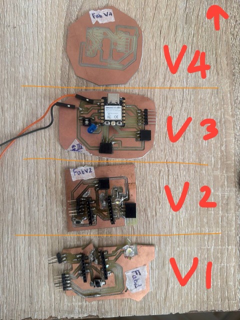
Progress and Test my PCB and MVP with different version
My First trial/Version 01
Test MVP circuit milled to use the ideal design and one bread board test the logic to work
First version PCb for my FP, 3D printing and assembling
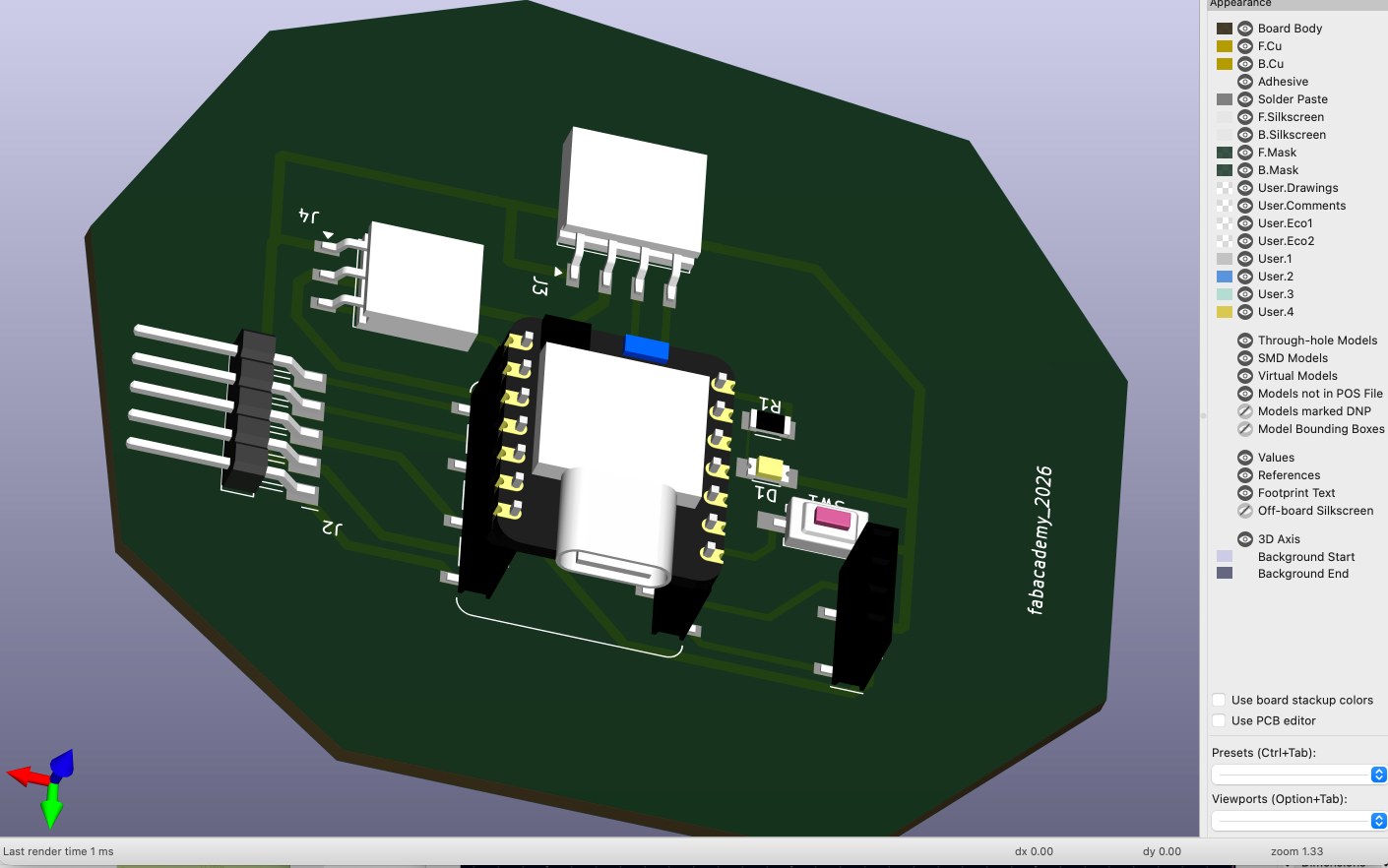
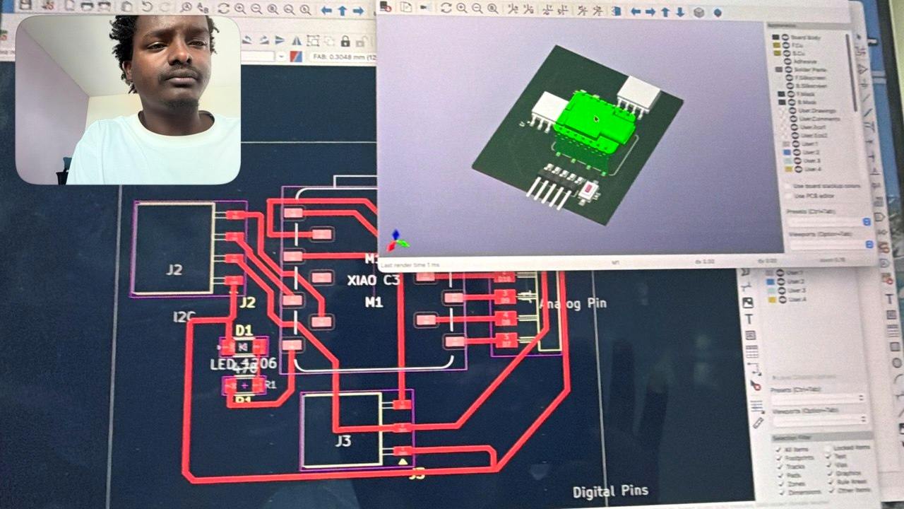
Kicad PCB Design
- Sketch
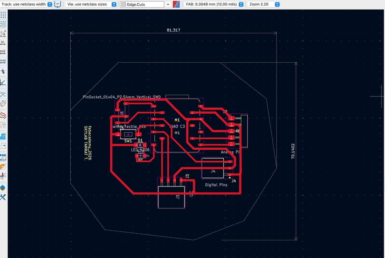
- Kicad PCB Design 3D view
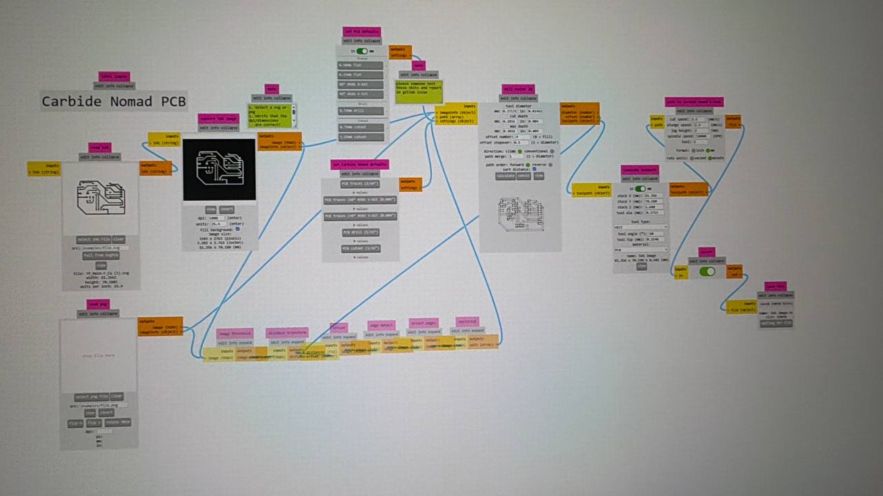
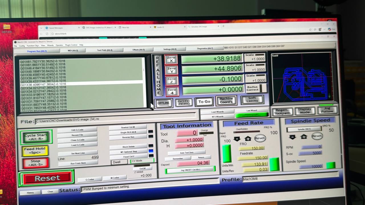
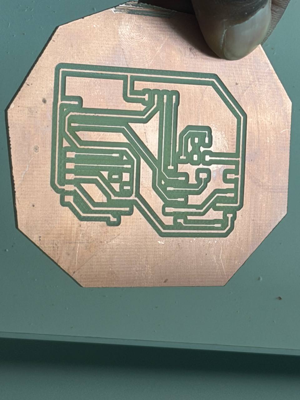
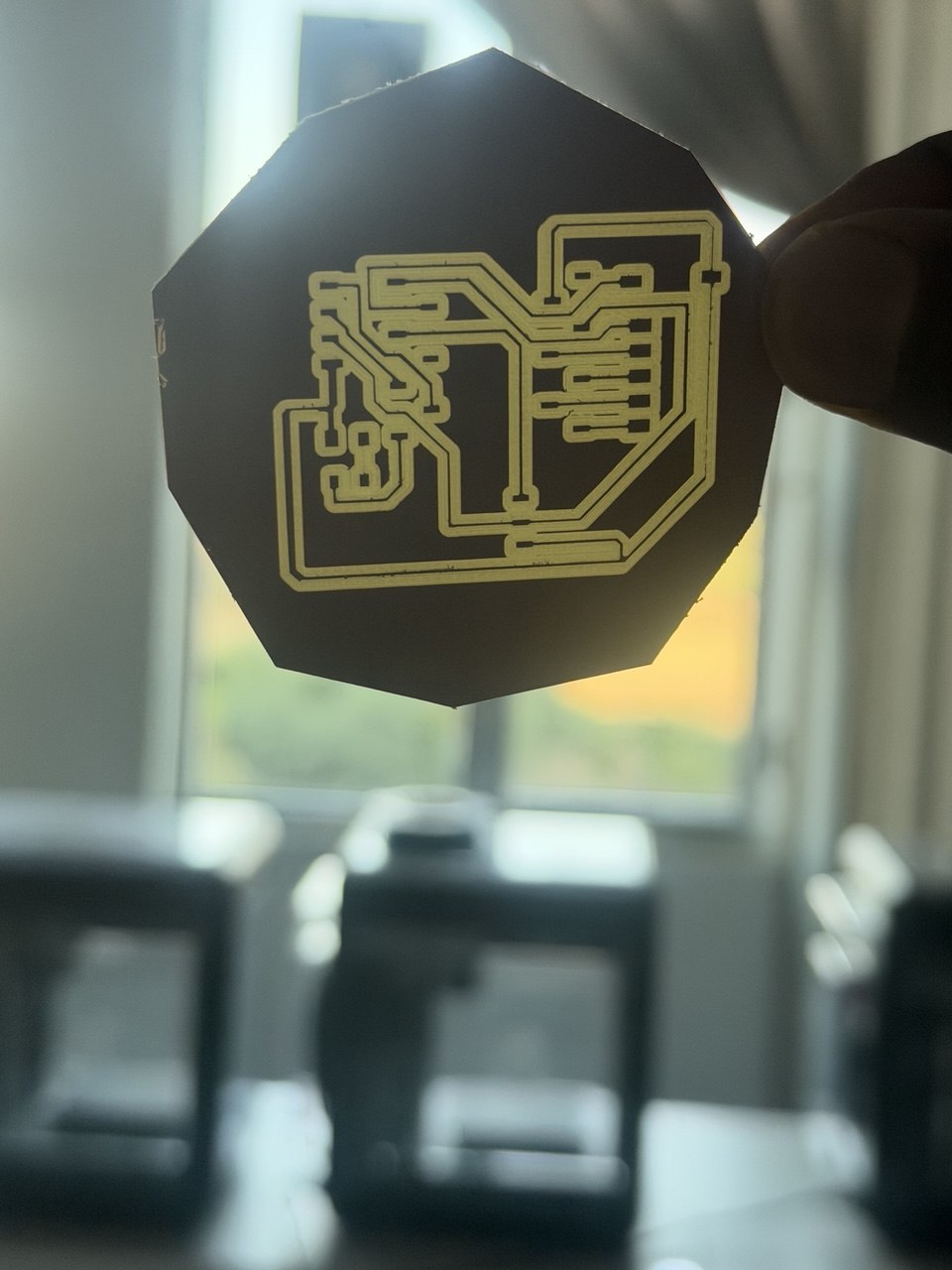
Milling
Mods Projects For Milling
March3 For Milling

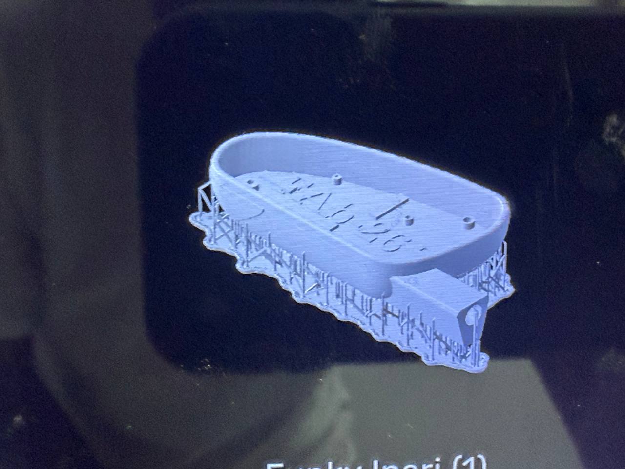
3D printing
The printing in my system follow two parts as described; cars main body and detachable/theft side system so, sometimes seeing twopart is common in my project🏃♀️
printing process
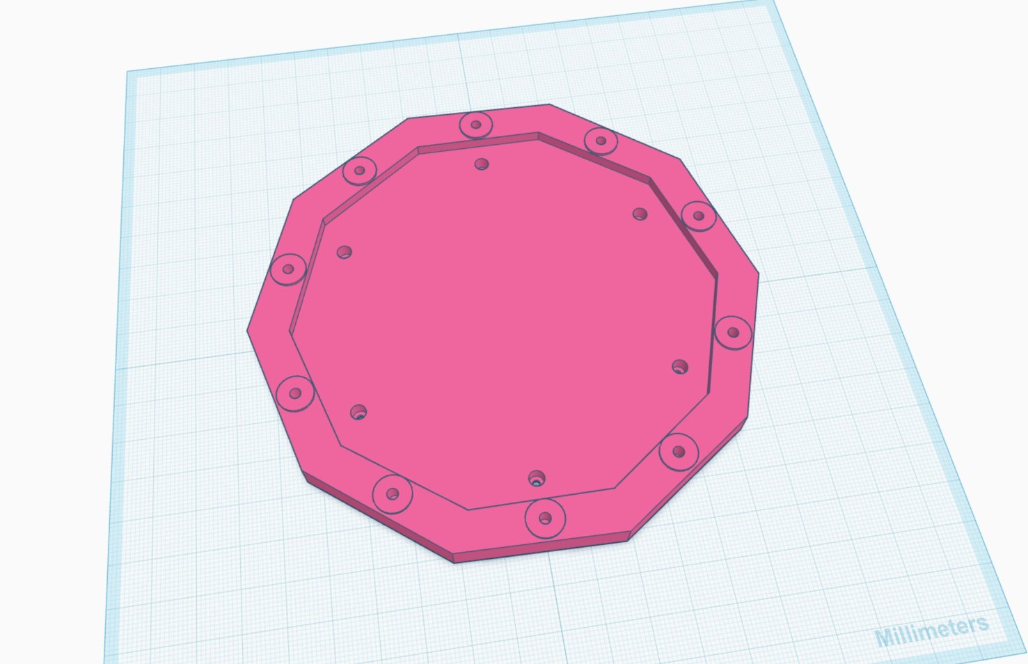
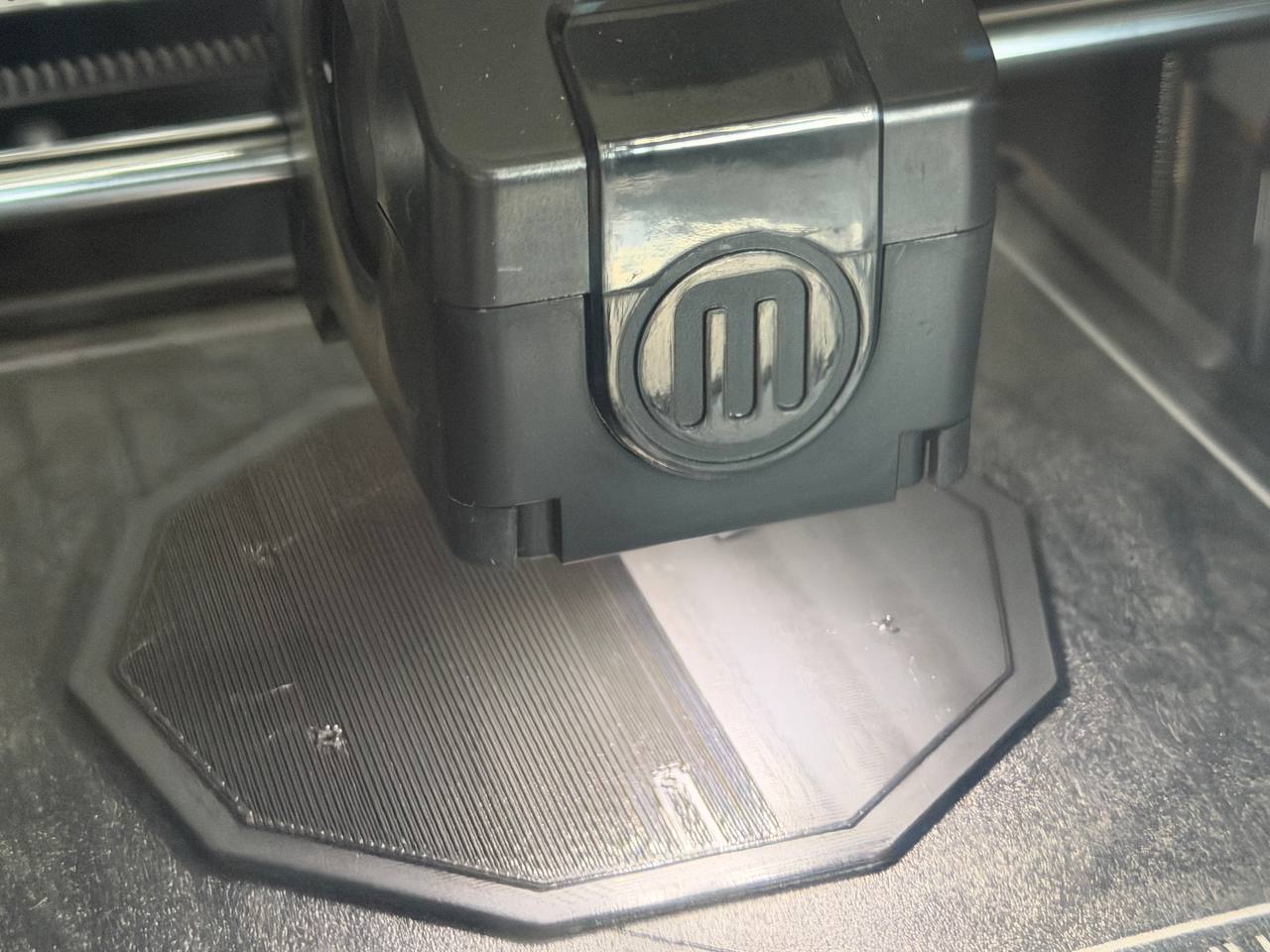
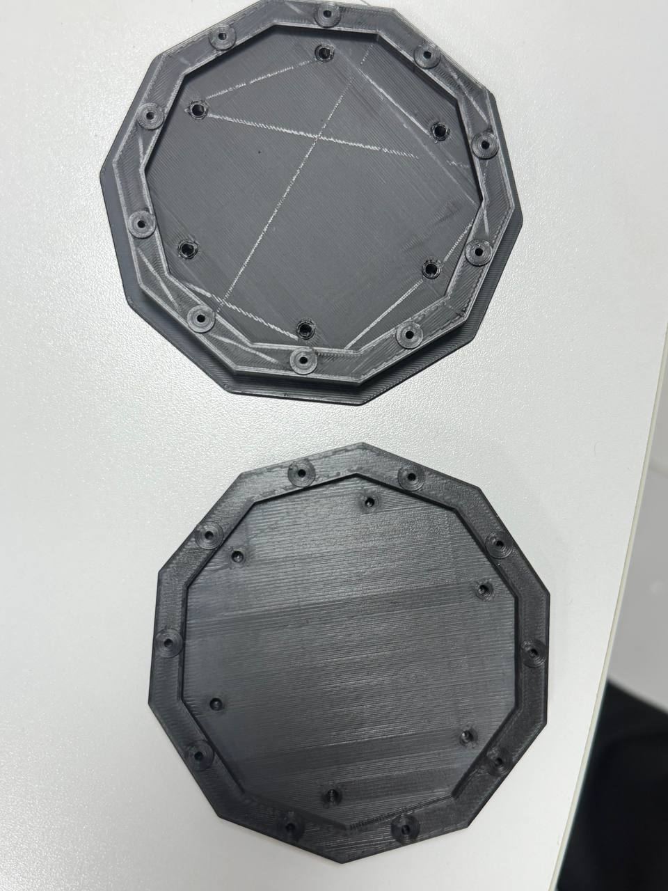
Final printed
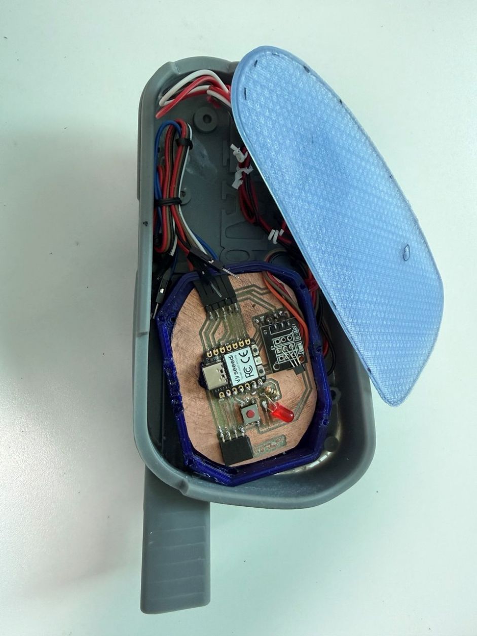
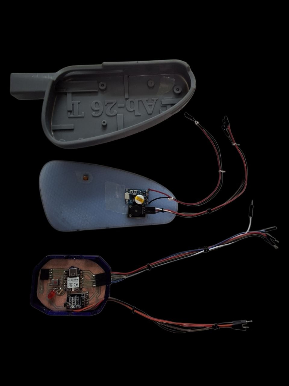
Assembling and difficulty
Wiring and connection
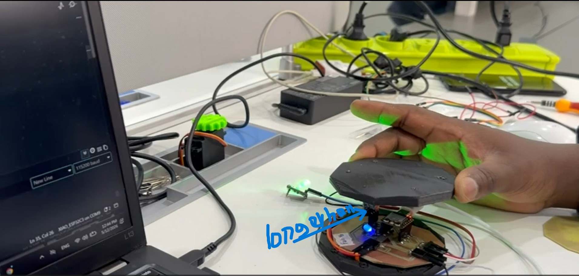
Test with version_01
This version is almost the same as System Integration week … systems is working as checked there
Difficulty
- During the 3D printing, I forget to include the wiring access and size of the PCB not aligned to press fit.
- Some of the equipment like the Hall Sensor a bit longer to use the minimal size to fit with the existing cars side mirror. 🤦♂️… Will next version will solve this?.
No access to wiring
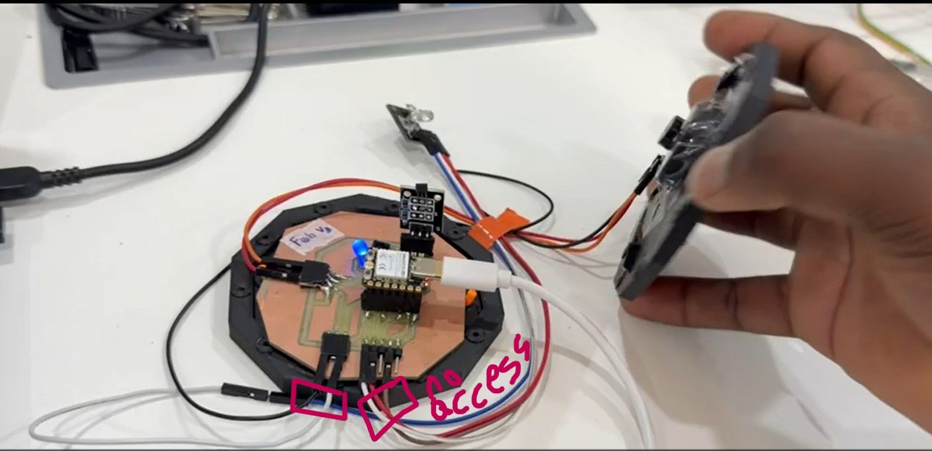
Longer Hall-effect Sensor*
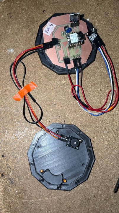
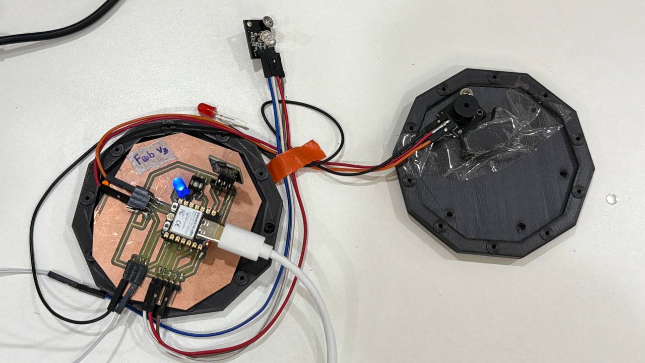
My 2nd attempt, trial/Version 02
This MVP version is especially modified for its enclosure (3D printing) and wiring of the circuit with a bit upgraded PCB quality and my enclosure layout is ready for assembly and troubleshooting again
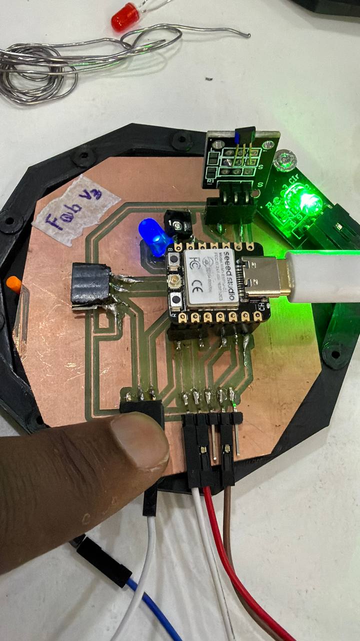
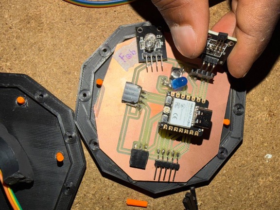
Second version PCb for my FP, 3D printing and assembling
Kicad PCB Design
- Sketch
- Kicad PCB Design 3D view
Milling

PCB V2
3D printing
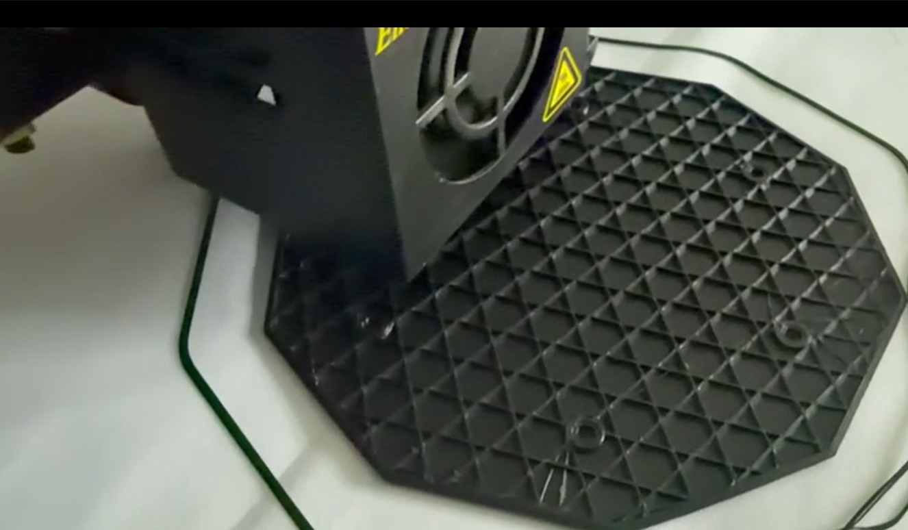
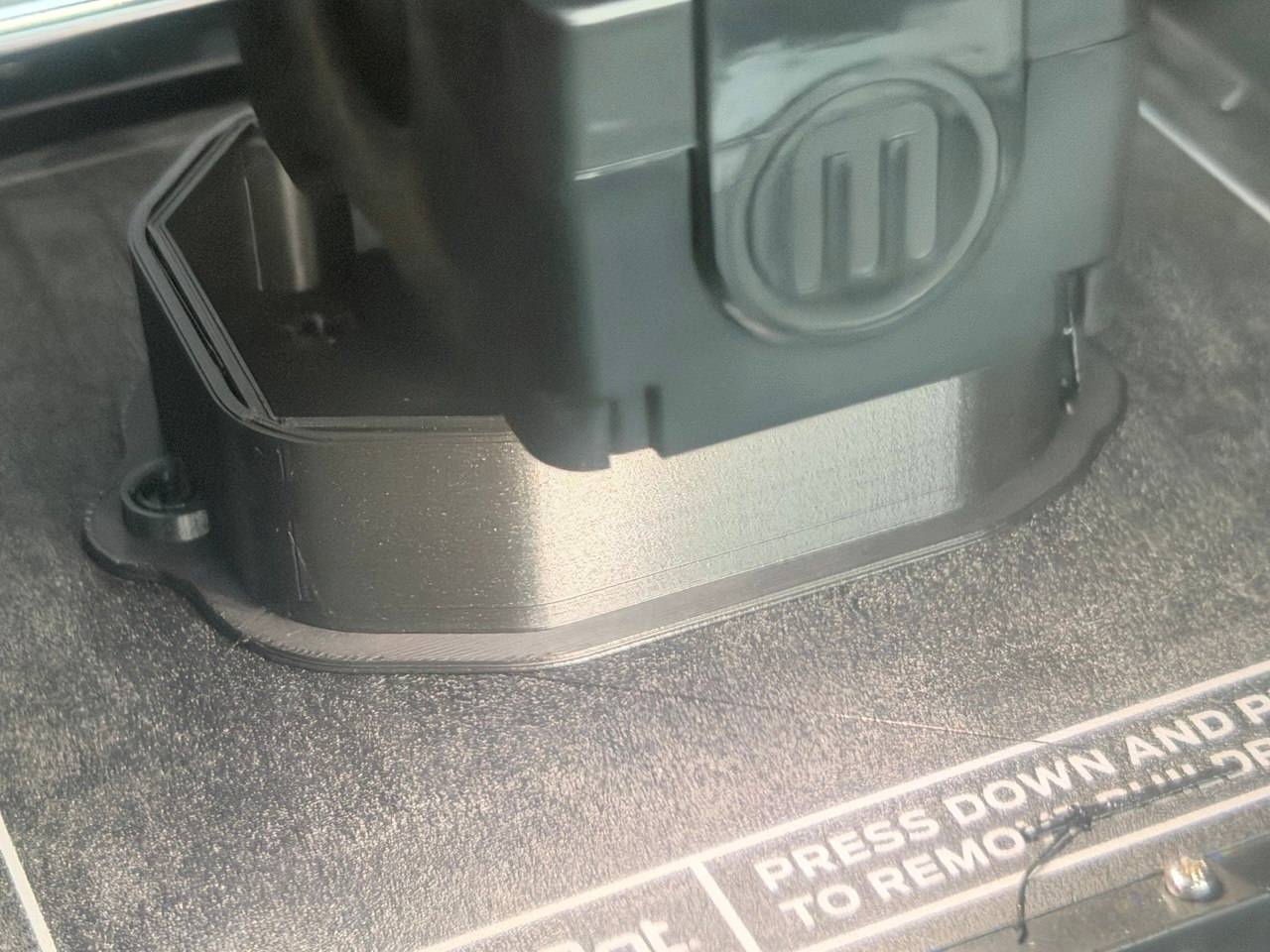
Here trying with two Additive Printing Process
-
FDM (Fused deposit modeling) using PLA
-
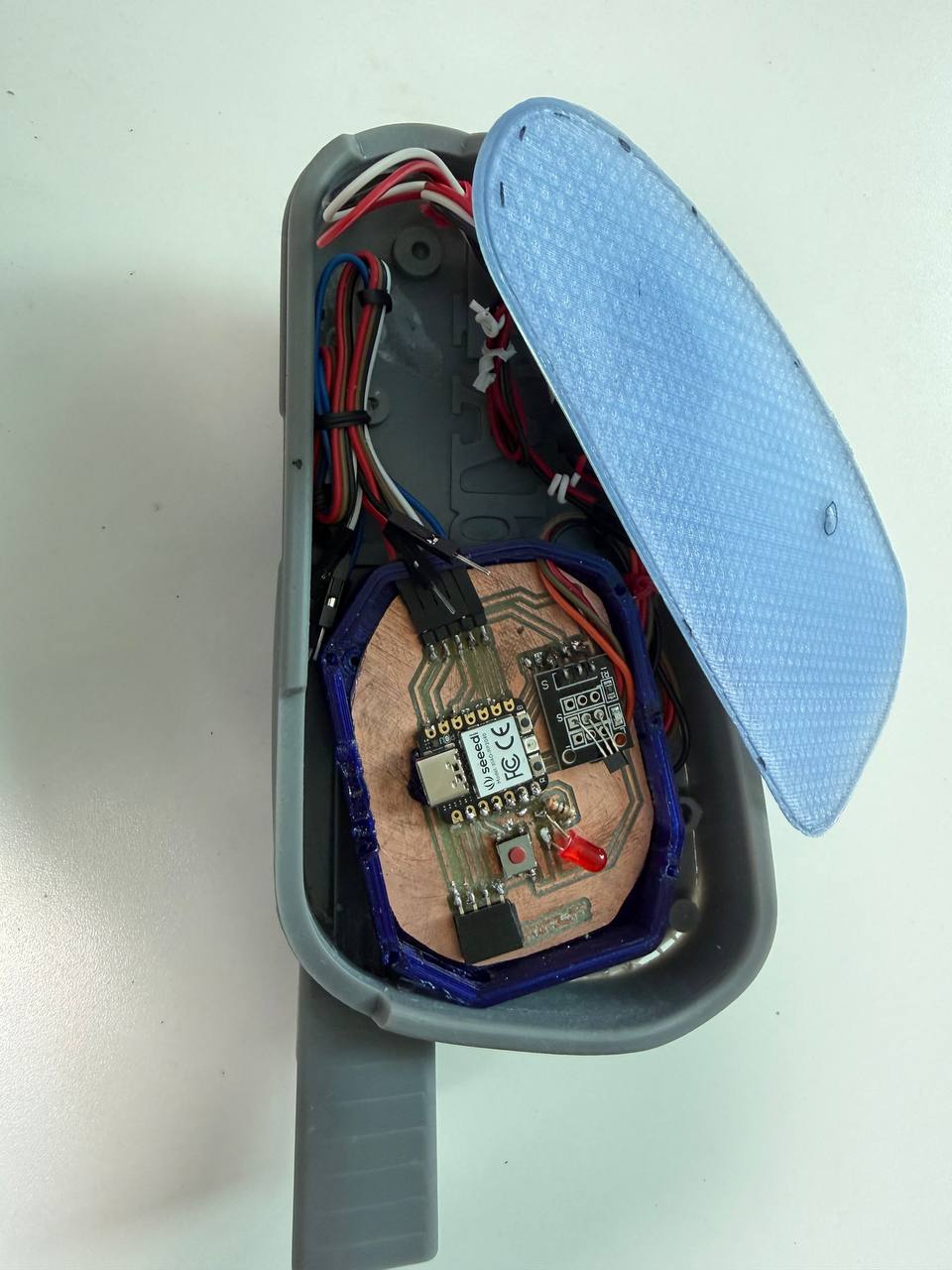
Main enclosure to hold MCU (XIAO C3), Hall Effect Sensor
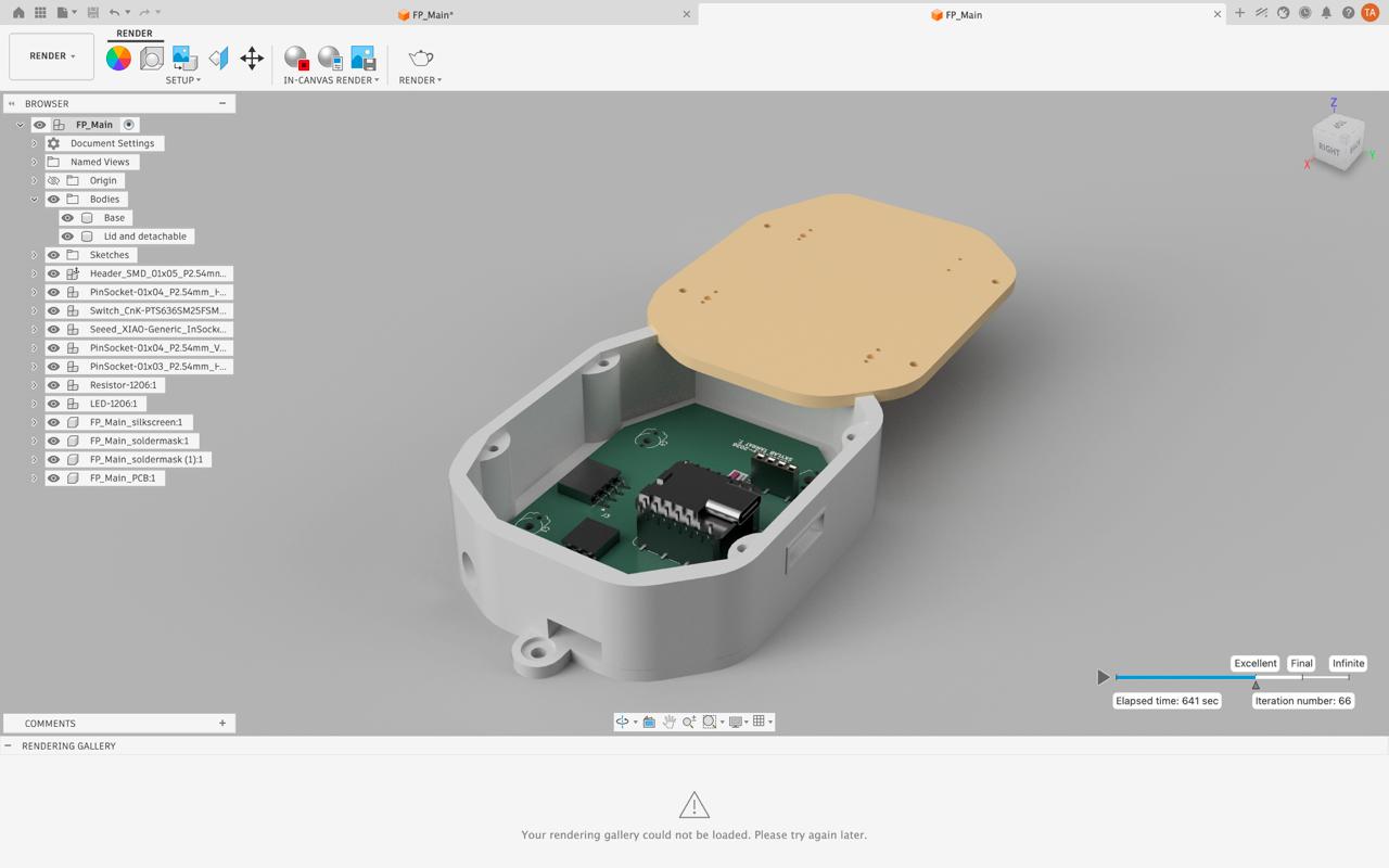
- Lid and detachable part holding magnet and buzzer (other optional equipments)
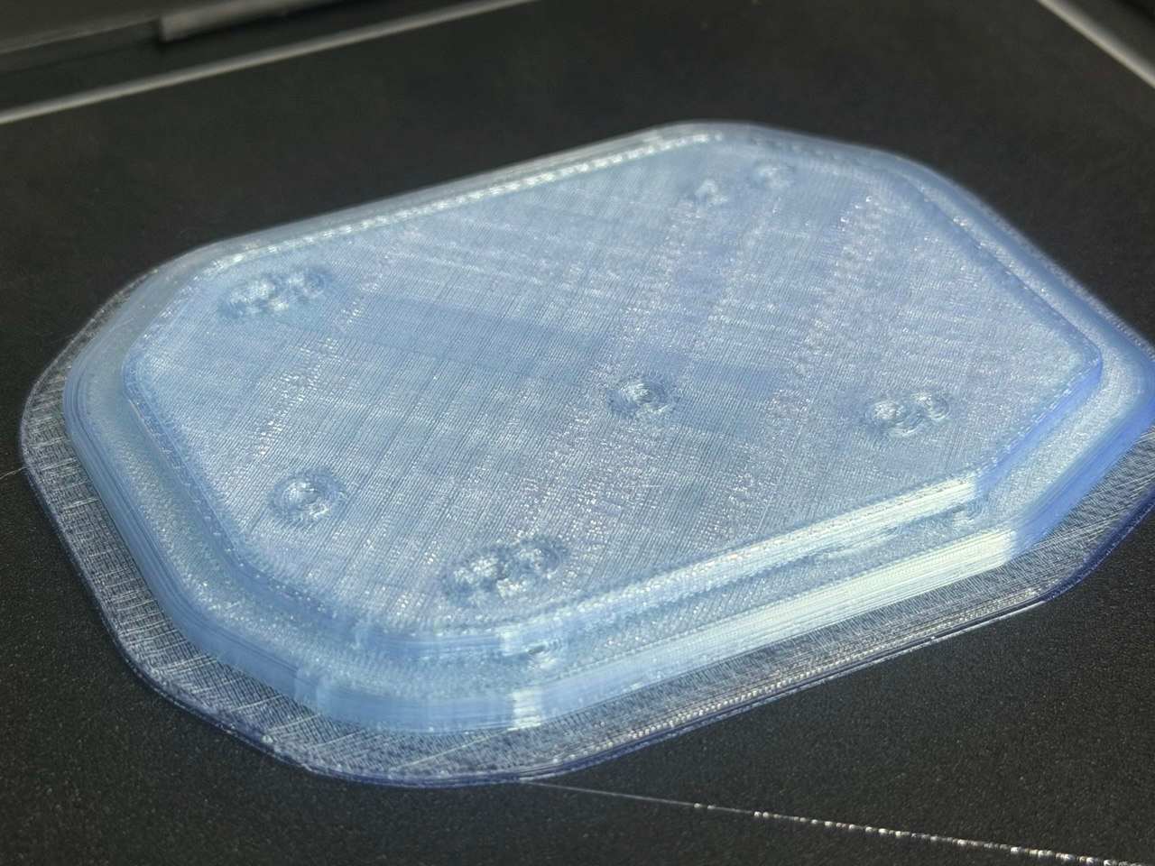
- SLA
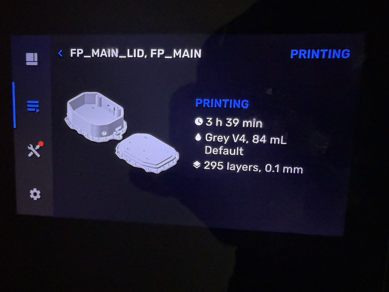
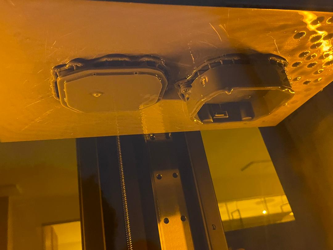
Soon install with my PCB (on curing) cured
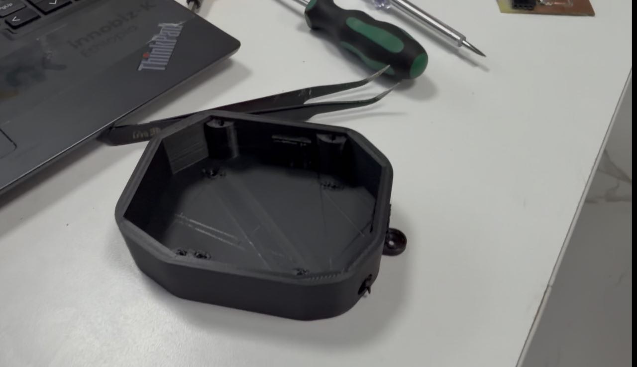
Final printed and assembled
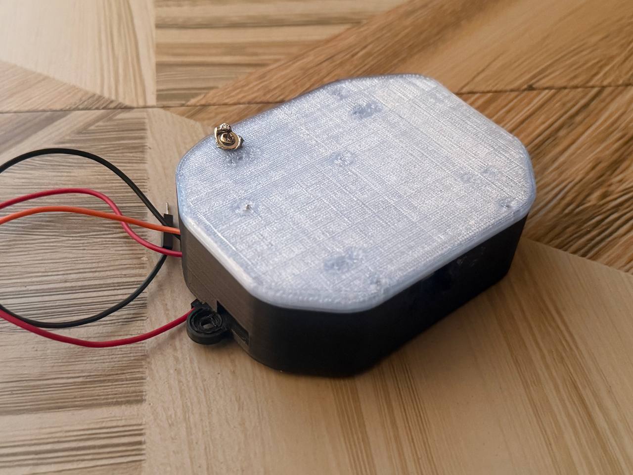
Assembling and difficulty
working on wiring and soldering
This version is almost the same as System Integration week on the oprational side… systems is working as checked there
Difficulty
Screw size selection and a bit alignment error …
No access to wiring solved
The project finalized as the following with a lot of update to the above progress
Electronics diagram finally with more simplified version

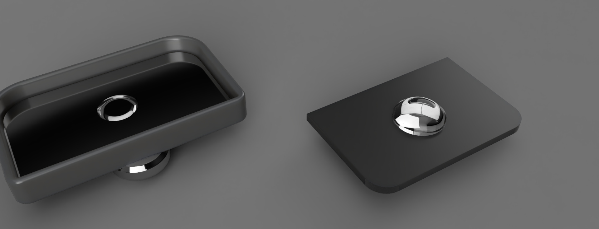
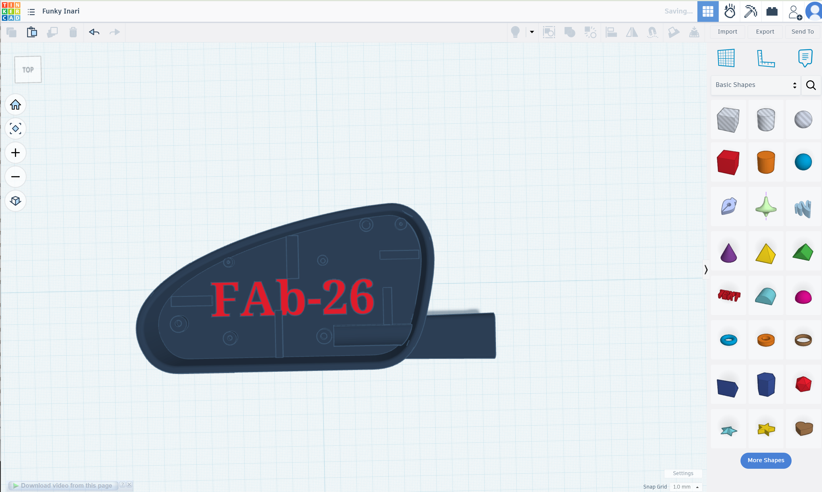
The final Enclosure shall add the design of imitation for car’s side mirror to test on it
Design in thinkercad for the fake enclosure for the test and assemble on it
3D printing with SLA and assembling
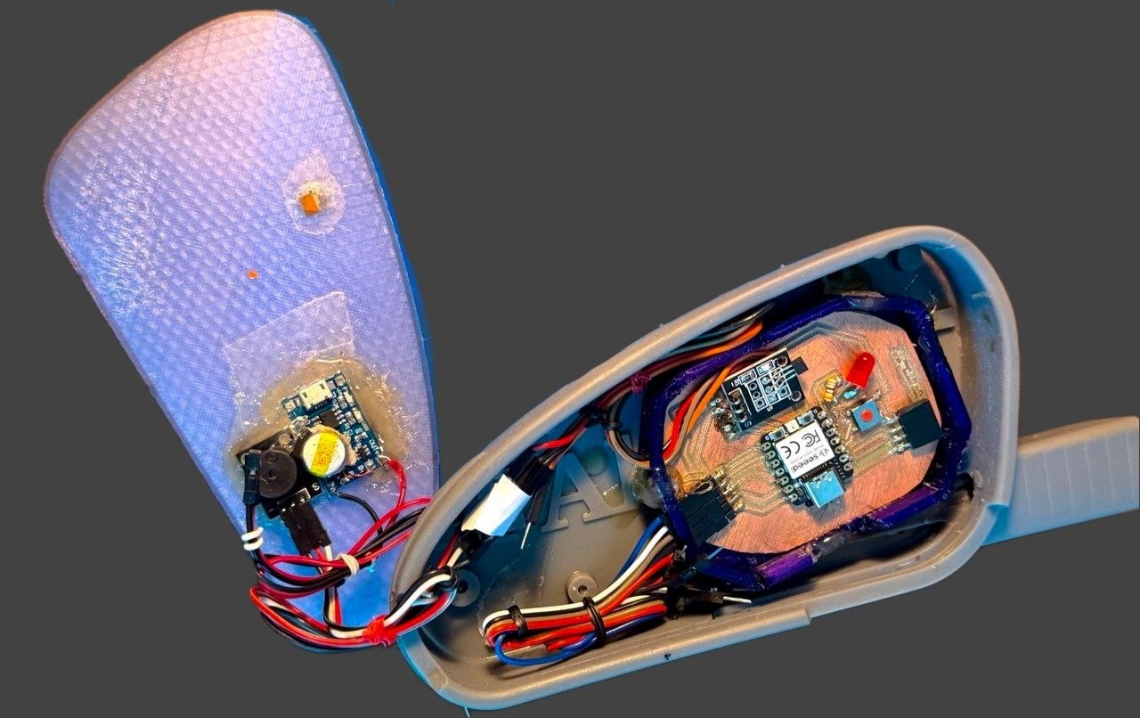
Wiring and cleaning
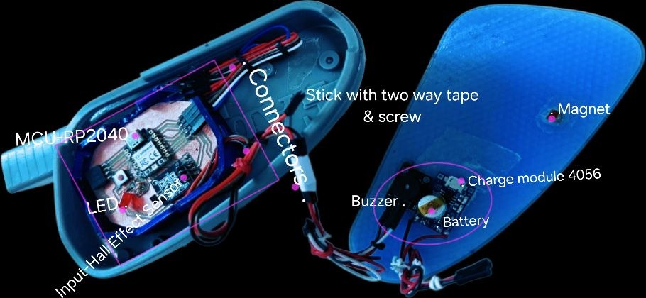
Secured with glue and two way tape used in cars
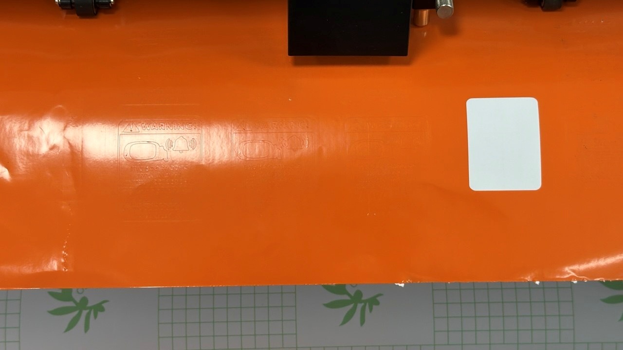
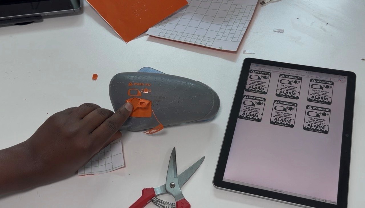
Vinyl warning sticker
- Inkscape for design sticker

- Cutting with C-48LX Contour Cutter Plotter
3.Post the sticker on the enclosure and glass
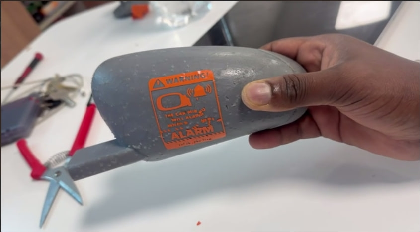
Functional testing
Back of the scene - My days setting more than ever on fabrication things for FP

File
I compressed a lot of files here: 👇 Compressed Files
Code used in the final with a bit modification than the system integration parts
AI: ChatGPT and Deepseek: with Prompts.. “define each codes line by line and debug for any errors I did to the hall sensor and buzzer IDE code”
const int hallPin    = D4;
const int ledPin     = D6;
const int triggerPin = D5;

// Alarm state
bool alarmTriggered = false;

// ========================================================
// SETUP
// ========================================================
void setup() {

  Serial.begin(115200);

  // Hall sensor
  pinMode(hallPin, INPUT_PULLUP);

  // LED
  pinMode(ledPin, OUTPUT);

  // Trigger output
  pinMode(triggerPin, OUTPUT);

  // Initial states
  digitalWrite(ledPin, LOW);
  digitalWrite(triggerPin, LOW);

  Serial.println("YeFab Leba Trap Starting...");

  startupTest();

  Serial.println("System Ready");
}

// ========================================================
// MAIN LOOP
// ========================================================
void loop() {

  int hallState = digitalRead(hallPin);

  Serial.print("Hall State: ");
  Serial.println(hallState);

  /*
     KY-003 Hall Sensor Logic

     LOW  = Magnet detected
     HIGH = Magnet removed
  */

  // ====================================================
  // SAFE STATE
  // ====================================================
  if (hallState == LOW && !alarmTriggered) {

    Serial.println("SAFE STATE");

    // LED ON continuously
    digitalWrite(ledPin, HIGH);

    digitalWrite(triggerPin, LOW);

    delay(100);
  }

  // ====================================================
  // THEFT DETECTED
  // ====================================================
  else if (hallState == HIGH && !alarmTriggered) {

    Serial.println("THEFT DETECTED!");

    // Flash LED rapidly
    for (int i = 0; i < 10; i++) {

      digitalWrite(ledPin, HIGH);
      delay(100);

      digitalWrite(ledPin, LOW);
      delay(100);
    }

    // Send trigger pulse to detachable PCB
    digitalWrite(triggerPin, HIGH);
    delay(150);
    digitalWrite(triggerPin, LOW);

    // Lock alarm state
    alarmTriggered = true;

    Serial.println("Alarm Trigger Sent");
  }

  // ====================================================
  // AFTER TRIGGER
  // ====================================================
  if (alarmTriggered) {

    // Slow blinking LED after alarm
    digitalWrite(ledPin, HIGH);
    delay(500);

    digitalWrite(ledPin, LOW);
    delay(500);
  }
}

// ========================================================
// STARTUP TEST
// ========================================================
void startupTest() {

  // Blink LED 3 times
  for (int i = 0; i < 3; i++) {

    digitalWrite(ledPin, HIGH);
    delay(200);

    digitalWrite(ledPin, LOW);
    delay(200);
  }
}
Referenced project from alumni Final project
AI: ChatGPT and Deepseek: with Prompts “Edit my writing for grammar” … ChatGPT “Generate the following images with persona/theft character with siren side mirror on hand” … Copilot