System Integration — Final Project
This week SSTM
Assignment
Design and document the system integration for the final project by showing how all subsystems work together as one complete product.
Introduction to System Integration to FP
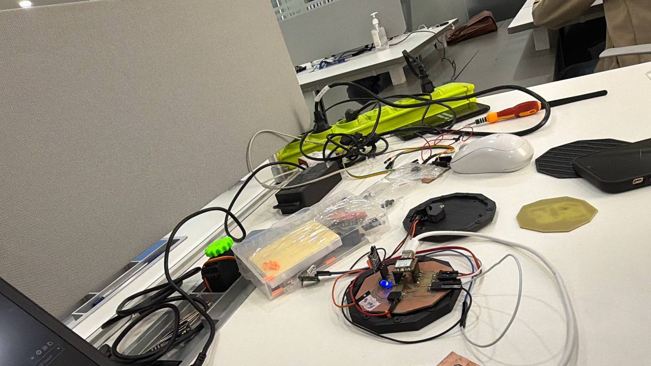
Here I tried to integrating all parts of the final project into one functional embedded system.
The project combines electronics, embedded programming, PCB design, mechanical structure, and sensor interaction into a complete fabricated product.
The system is designed around the XIAO ESP32-C3 microcontroller and a KY-003 Hall effect sensor for magnetic field detection and alarm triggering.
stolen side mirror glass part
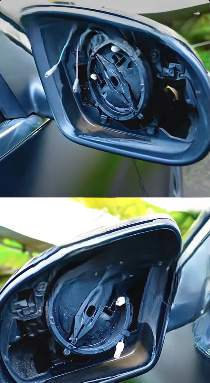

Device added to car mirror to sound an alarm when the mirror is detached
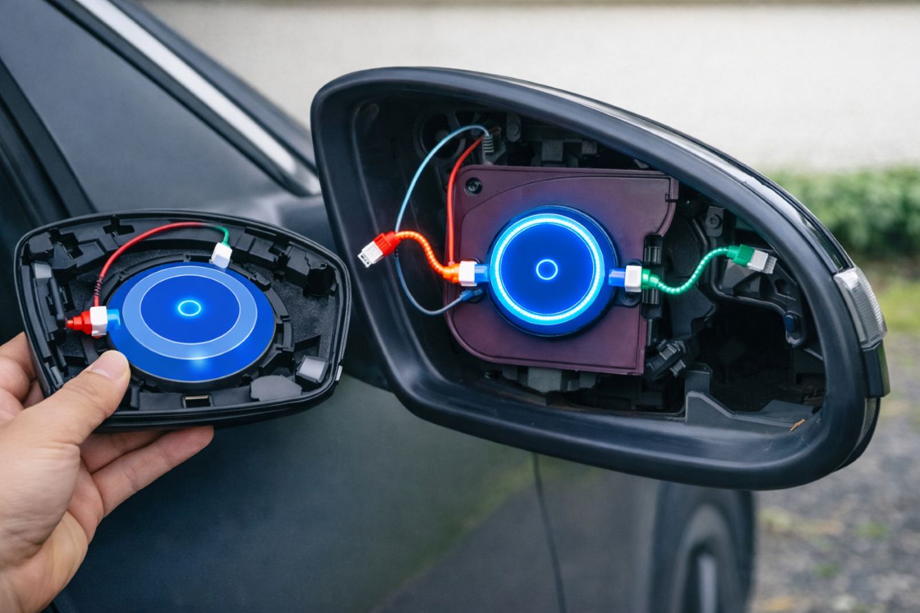
Source: (edited with AI copilot from image 1 and 2 with prompt “combine the following side mirror in two detachable and base parts with electronics equipment to both”)
## My basic ideas in the two parts of the cars (Fixed side and detachable)
Project Overview
Final Project Description
My final project is a theft detection system for car parts, particularly the car side mirror, which is vulnerable to theft in my city. Using a Hall Effect sensor in the side mirror housing to detect a magnet attached to the back of the mirror, an alarm will be triggered when the sensor detects a distance greater than a threshold value. A Xiao ESP32 C3 processes the sensor signal and activates an LED.
Main Features
- Magnetic field detection using KY-003 Hall sensor
- Visual feedback using indicator LED
- Compact custom PCB design
- Embedded programming with ESP32-C3
- Custom fabricated enclosure and mounting system
Expected Functionality
The system continuously monitors the Hall effect sensor input.
When magnetic detection occurs, the ESP32-C3 activates the output LED and processes the event in real time.
Main Function of my project
my project is divided into the following subsystems.
Mechanical System
- Enclosure structure
- PCB mounting system
- Sensor positioning
- Cable organization
Electronics System
- XIAO ESP32-C3 micro controller
- KY-003 Hall effect sensor
- Status LED with resistor
- Push button switch
- Power distribution circuit
- Pin headers and connectors
It had Software
- Sensor reading
- Digital signal processing
- LED output control
- System monitoring
Communication System
- GPIO digital communication
- USB programming interface
- Optional I2C expansion header

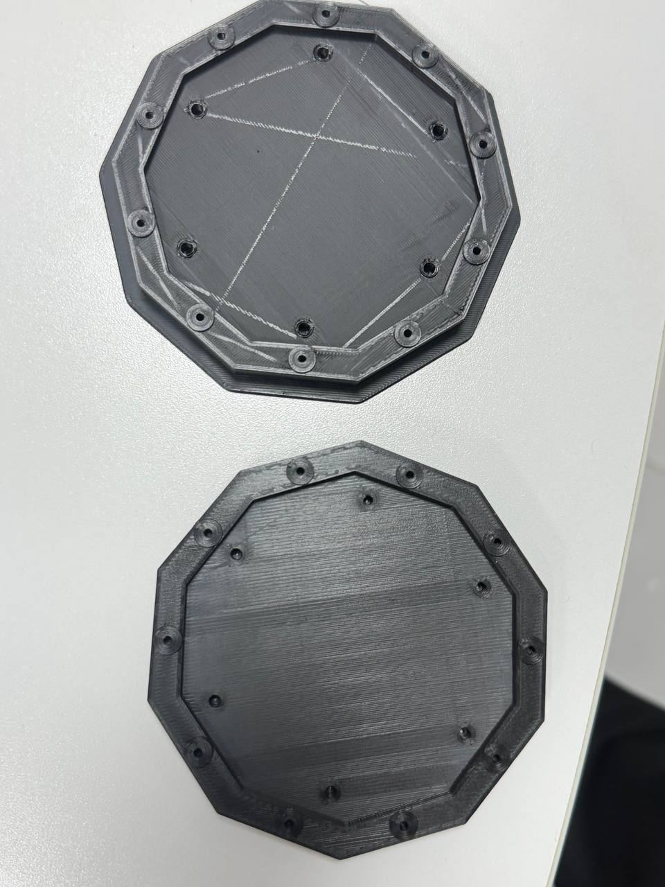
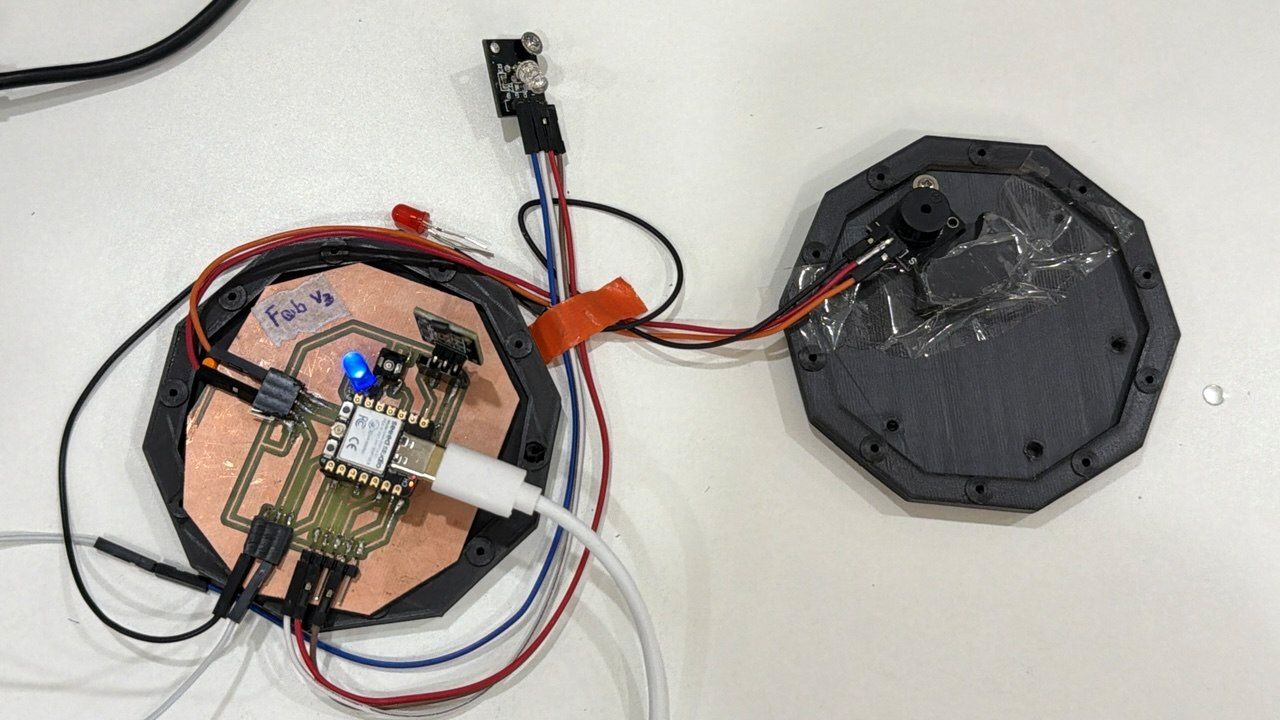
Structure Design
The enclosure was designed to securely hold the PCB, sensor, and wiring while maintaining a compact and organized structure.
The design also improves protection, accessibility, and final product appearance.
Assembly Process
The assembly process includes:
- PCB fabrication using FR4 material
- Soldering electronic components
- Installing the Hall sensor
- Mounting the XIAO ESP32-C3
- Organizing wiring connections
- Final enclosure assembly
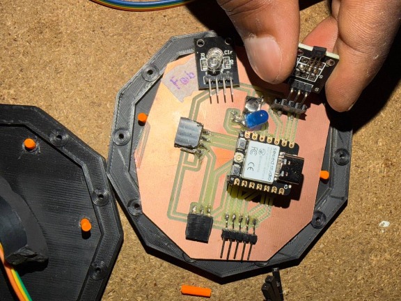
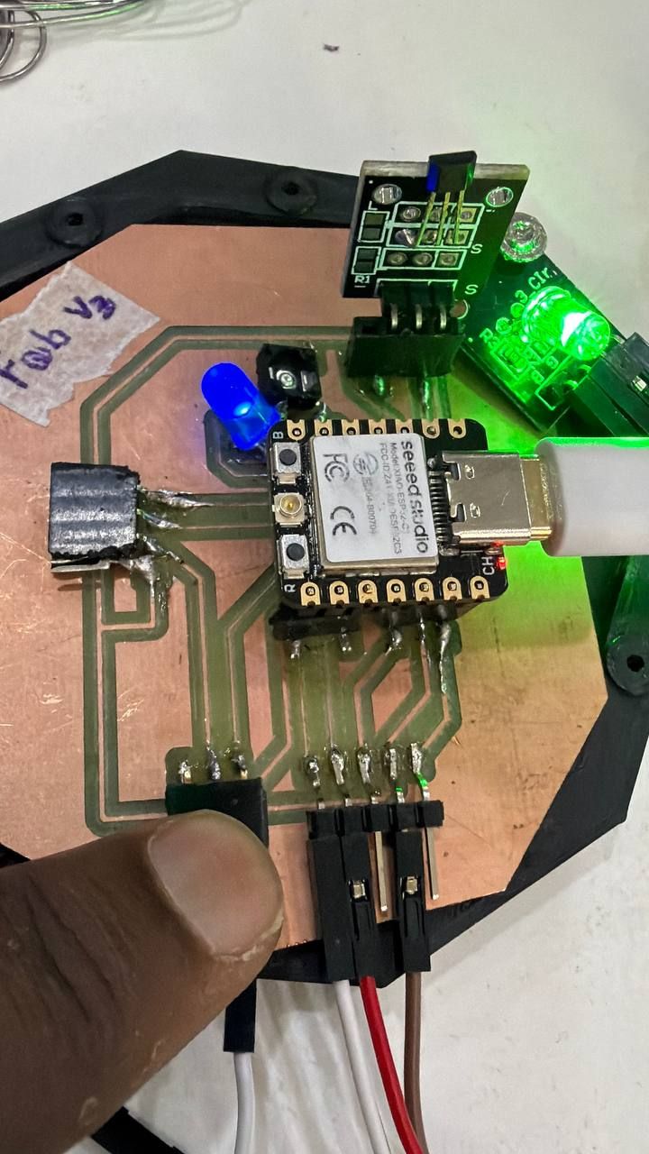
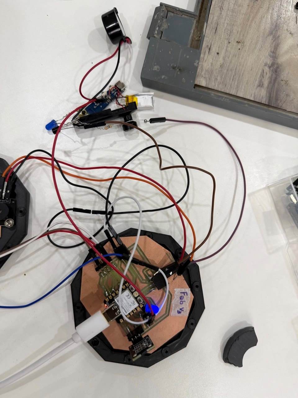
Electronics Integration
Main Electronics Components
- XIAO ESP32-C3
- KY-003 Hall effect sensor
- LED with resistor
- 3-pin horizontal SMD socket
- 2-pin I2C horizontal header
- USB power connection
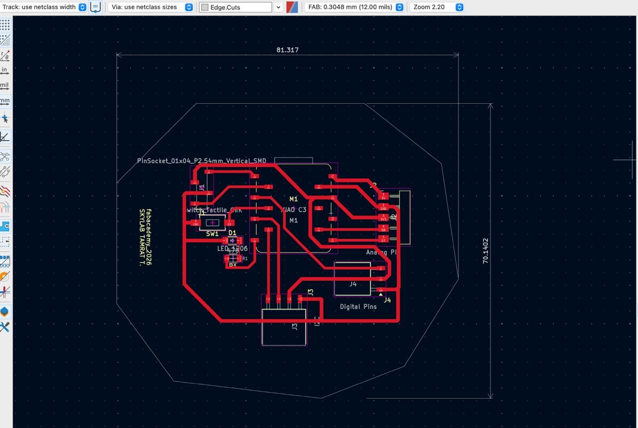
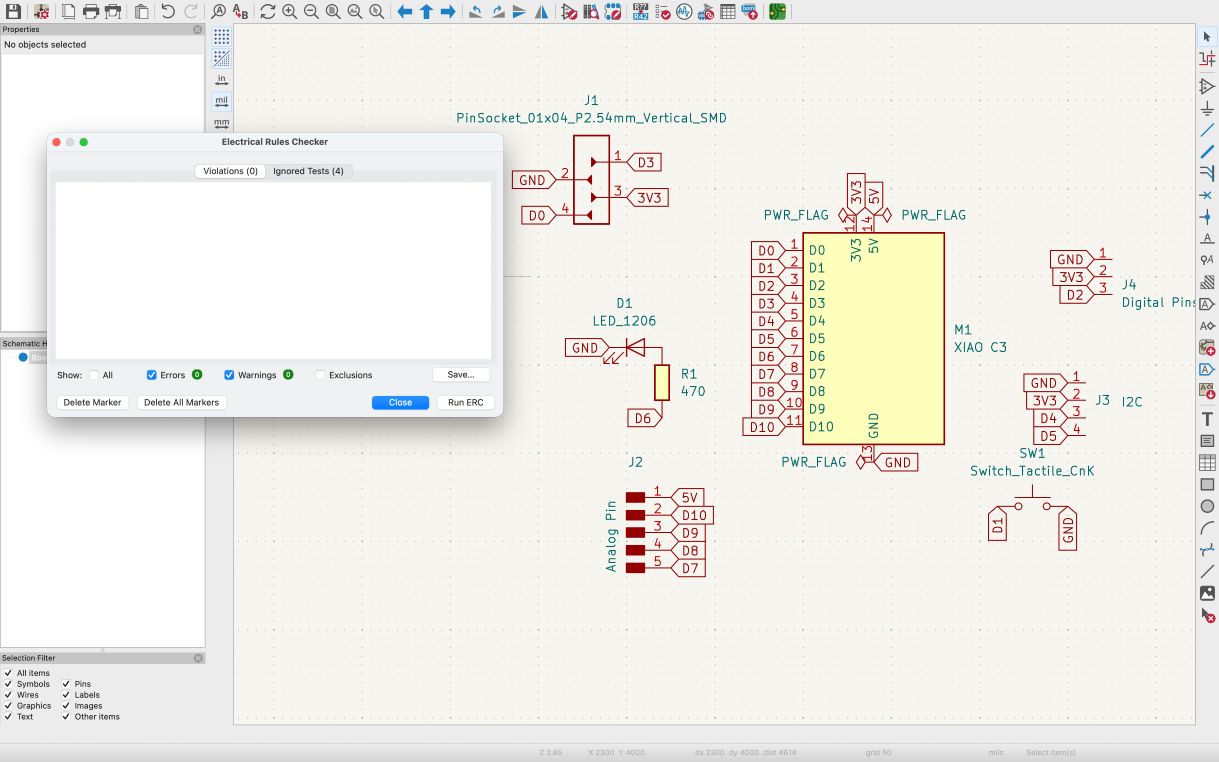
PCB Integration
The PCB was designed in KiCad and integrated into the enclosure with proper connector placement and organized routing.
Important considerations included:
- Short signal paths
- Stable grounding
- Reliable sensor connection
- Proper 3.3V power distribution
- Easy soldering and maintenance
Wiring Integration
The wiring system includes:
- 3.3V power lines
- GND connections
- Sensor signal routing
- LED output wiring
- Push button connections
Organized wiring improves reliability, safety, and easier debugging.
Software Integration
Firmware Architecture
The firmware controls the complete system by integrating sensor input and output responses using the ESP32-C3.
The software continuously reads the Hall sensor signal and updates the LED output accordingly.
Embedded Programming
The firmware was developed using the Arduino IDE for the XIAO ESP32-C3.
Main software functions include:
- Digital sensor reading
- Output control
- Event detection
- Serial debugging
Code from AI ChatGPT Prompt: :Combine the following sys and Generate the code for XIAO “ESP32-C3 Hall Sensor + RGB LED + Buzzer Alarm System”
/*
   XIAO ESP32-C3
   Hall Sensor + RGB LED + Buzzer Alarm System

   Pin Connections

   Hall Sensor OUT  -> D0
   RGB Red          -> D2
   RGB Green        -> D7
   RGB Blue         -> D8
   Buzzer           -> D3

 Behavior

   Startup:
     Red -> Green -> Blue -> White + Beep

   Safe State:
     Solid Green

   Alarm State:
     Alternating Red/Blue
     Pulsing buzzer

   -------------------------------
   IMPORTANT
   -------------------------------
   - Power Hall sensor from 3.3V
   - Code assumes COMMON-CATHODE RGB LED
   - Serial baud: 115200
*/

const int hallPin   = D0;

const int redPin    = D2;
const int greenPin  = D7;
const int bluePin   = D8;
const int buzzerPin = D3;

// -------------------------------
// Setup
// -------------------------------
void setup() {

  Serial.begin(115200);

  pinMode(hallPin, INPUT_PULLUP);

  pinMode(redPin, OUTPUT);
  pinMode(greenPin, OUTPUT);
  pinMode(bluePin, OUTPUT);

  pinMode(buzzerPin, OUTPUT);

  // Turn everything OFF first
  setRGB(LOW, LOW, LOW);
  digitalWrite(buzzerPin, LOW);

  Serial.println("System Starting...");

  startupTest();

  Serial.println("System Ready");
}

// -------------------------------
// Main Loop
// -------------------------------
void loop() {

  int hallState = digitalRead(hallPin);

  Serial.print("Hall State: ");
  Serial.println(hallState);

  // Most Hall sensors:
  // LOW = magnet detected
  // HIGH = no magnet

  if (hallState == LOW) {

    // -------------------------
    // ALARM MODE
    // -------------------------
    Serial.println("MAGNET DETECTED!");

    // Red ON
    setRGB(HIGH, LOW, LOW);
    tone(buzzerPin, 2000);
    delay(200);

    // Blue ON
    setRGB(LOW, LOW, HIGH);
    noTone(buzzerPin);
    delay(200);

  } else {

    // -------------------------
    // SAFE MODE
    // -------------------------
    Serial.println("Safe State");

    // Solid Green
    setRGB(LOW, HIGH, LOW);

    noTone(buzzerPin);

    delay(100);
  }
}

// -------------------------------
// RGB Helper Function
// -------------------------------
void setRGB(bool redState, bool greenState, bool blueState) {

  digitalWrite(redPin, redState);
  digitalWrite(greenPin, greenState);
  digitalWrite(bluePin, blueState);
}

// -------------------------------
// Startup LED/Buzzer Test
// -------------------------------
void startupTest() {

  // RED
  setRGB(HIGH, LOW, LOW);
  tone(buzzerPin, 1000);
  delay(300);

  // GREEN
  setRGB(LOW, HIGH, LOW);
  tone(buzzerPin, 1200);
  delay(300);

  // BLUE
  setRGB(LOW, LOW, HIGH);
  tone(buzzerPin, 1500);
  delay(300);

  // WHITE (all colors)
  setRGB(HIGH, HIGH, HIGH);
  tone(buzzerPin, 2000);
  delay(500);

  // OFF
  setRGB(LOW, LOW, LOW);
  noTone(buzzerPin);

  delay(200);
}
Power Management
My project uses USB power/Battery supplied to the XIAO-C3 board. It will control the
- Hall effect sensor
- Indicator LED
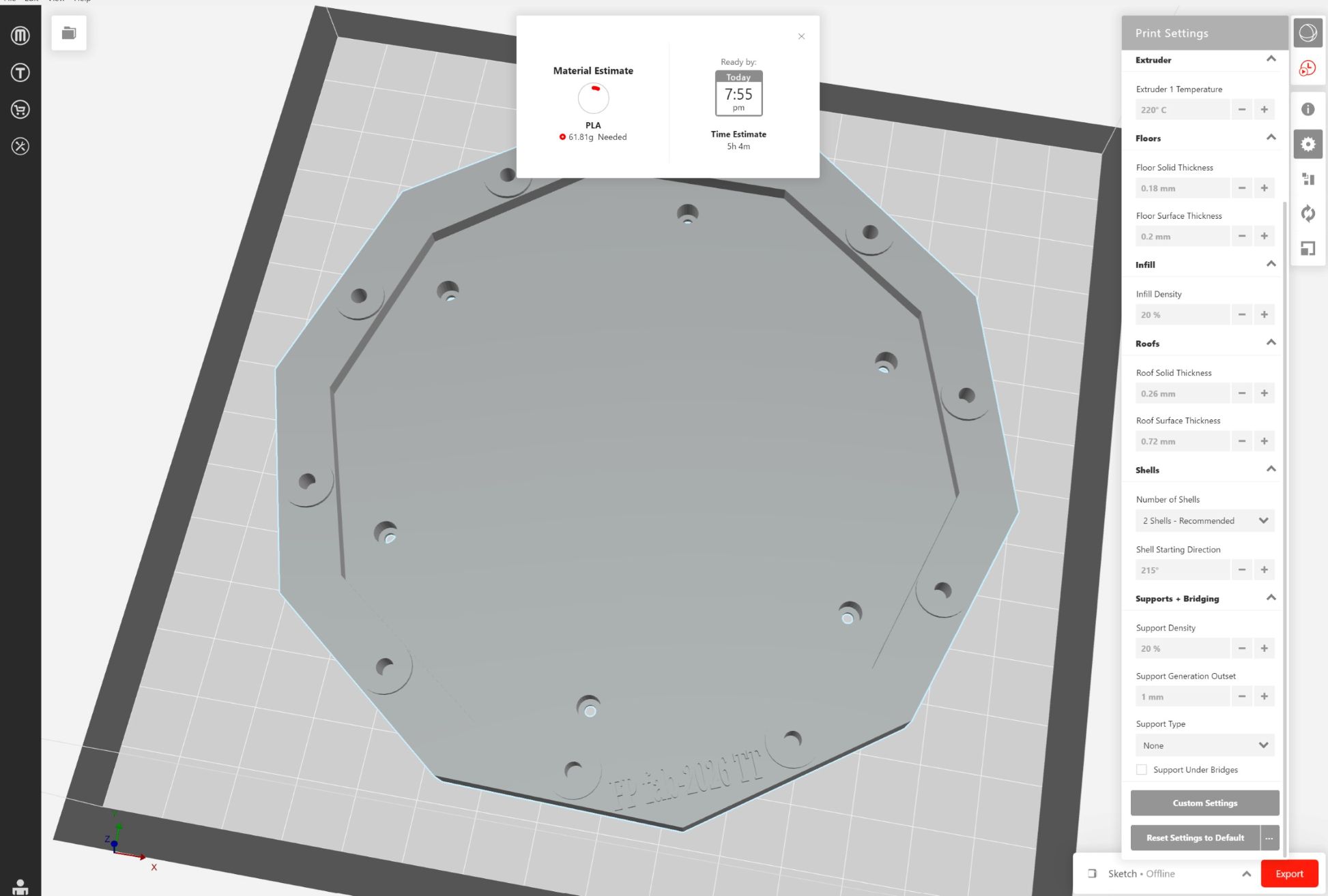
Enclosure Design
The enclosure was designed to transform the prototype into a compact and organized product.
Testing & Debugging
System Testing
The full system was tested to verify:
- Hall sensor detection
- LED functionality
- Stable power operation
- PCB connectivity
- Firmware response
Debugging Process
Several issues were identified and corrected during development.
Mechanical Issues
- PCB mounting alignment
- Sensor positioning
Electronics Issues
- Loose solder joints
- Incorrect GPIO connections
- Power instability
My full system failure analysis
Possible failure Modes in car detachment detection
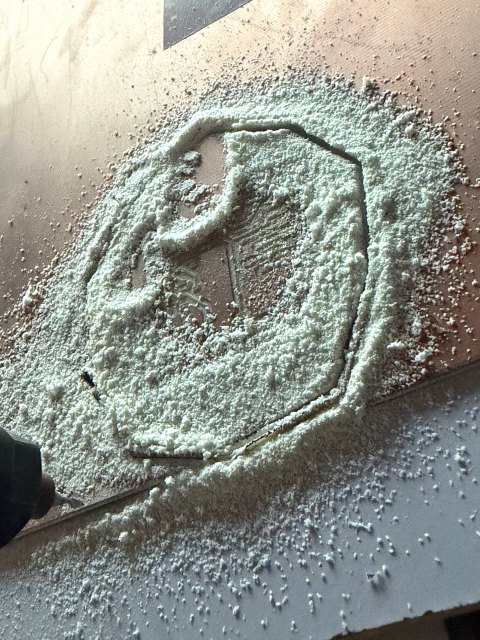
Mechanically the project face the following when i test and assemble
- Weak enclosure mounting
- Sensor misalignment
- when failed some button detached
As solutions I did
- Improved PCB mounting and add more the space
- Better cable organization by color and solder them when necessary (recommended by Rico)
- Stable voltage distribution
- Firmware optimization and testing
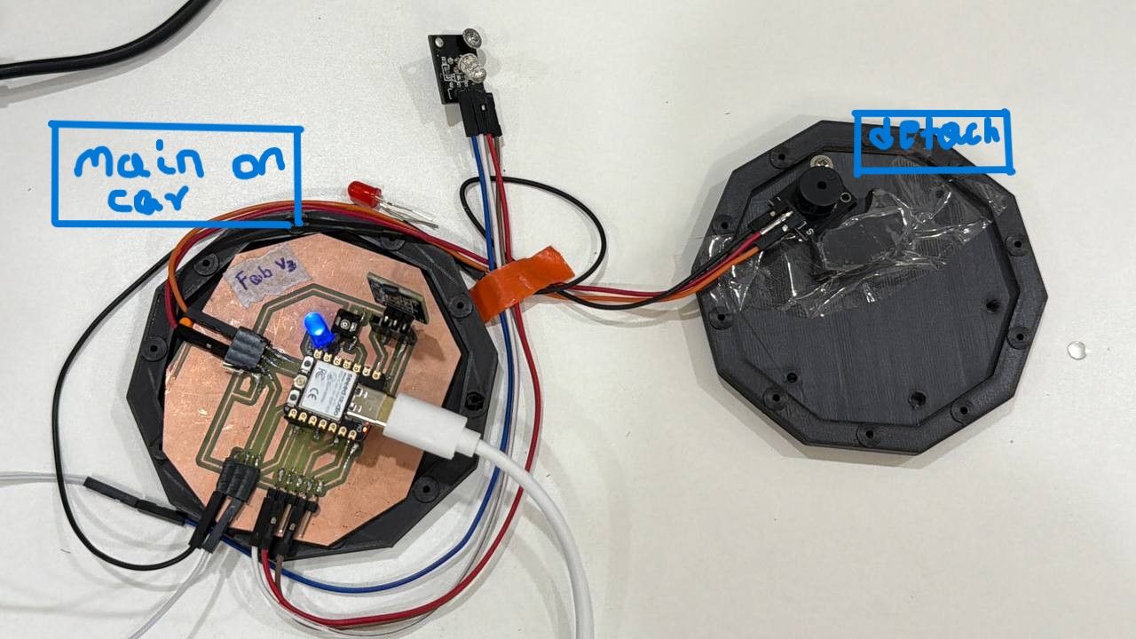
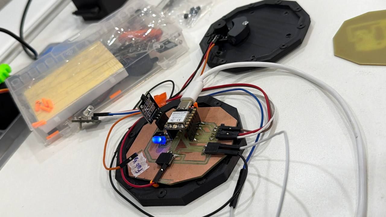
Final Assembly Progress I done
After integrating all systems:
- PCB was mounted on the 3D printed enclosure
- Components were soldered on their designed spot
- Firmware was uploaded to the MCU to sense the detachment and LED to give light
- Wiring was organized as recommended
- Then enclosure was assembled
- Finally the testing was done … Good and it is as expected
Final Result
The project successfully demonstrates integration between:
- Embedded electronics & programming
- PCB fabrication
- Sensor systems
- Mechanical enclosure design
Video Demo
Reflection
This assignment improved my understanding of complete system integration and embedded product development.
I learned how to combine:
- PCB design
- Embedded programming
- Sensor integration
- Mechanical assembly
- Product documentation
The project also improved my workflow in:
- KiCad PCB design
- ESP32-C3 programming
- Digital fabrication
- System debugging
- Final project integration
Files working on
Design Files
- Schematics
- KiCad PCB files
- Firmware source code
- CAD models
Fabrication Files
- STL files
- SVG files


References
- Fab Academy documentation
- Final Project documentation
- KY-003 Hall sensor datasheet
- XIAO ESP32-C3 documentation
- KiCad documentation
- Arduino IDE resources