Week05 3D Scanning and Printing
In Week 05 started with intensive describtion from Proff. Neil and the Senior Scientist on the sector. I explored the complete workflow of 3D scanning and additive manufacturing, learning how to capture real-world objects digitally and reproduce them through 3D printing and I also studied key additive manufacturing concepts such as layer-by-layer fabrication, infill structures, supports, tolerances, and material behavior, print some design/models that cannot be made with the subtractive methods.
Reference class page:
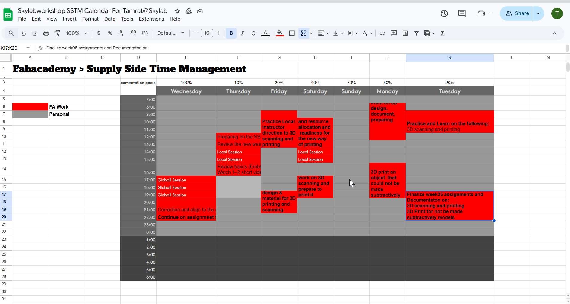
My SSTM
Start with Local Sessions
During Week 05, I learned the fundamentals of 3D printting, scanning and how software working for 3D printing. We introduced to tools, methods,must to do and documentation status update and followup as well how to access the assesment platform. Then additive method by Rico. a. Initail design to thinkercad with Rico
Source: Local instructor, Rico
b. Progress to the additive aligned design
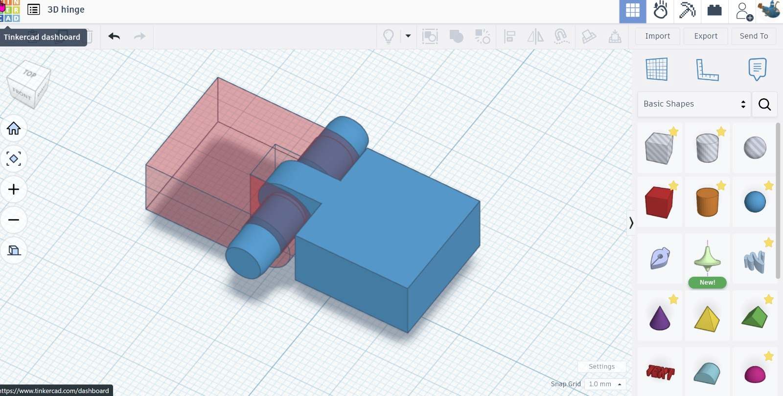
Source: Local instructor, Rico
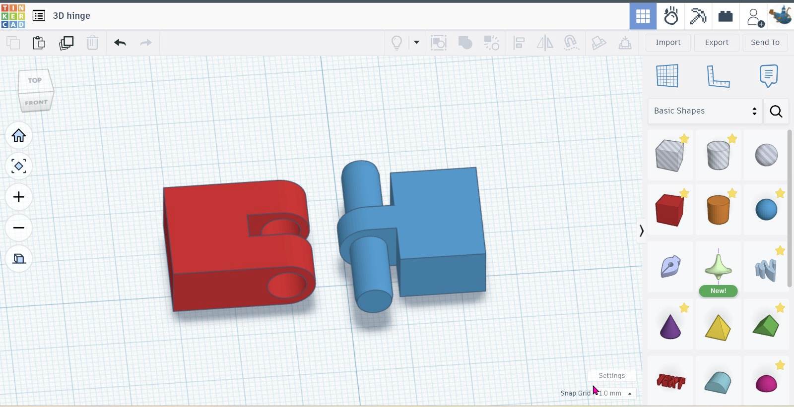
c. Ready to 3D print for additive Manufacturing (hard to subtractive method)
 Source: Local instructor, Rico
Group assignment
B. Individual assignment
Design, Document, and 3D Print an Object That Could Not Be Made Subtractively
Learning Outcomes
- Understanding of Design for Additive Manufacturing (DfAM)
- Designing internal cavities
- Managing overhangs and supports
- Tolerance and wall thickness control
- Optimizing print settings
Objective
Design and fabricate a small 3D object (few cm³) that cannot be produced using subtractive manufacturing (e.g., CNC milling).
Why It Cannot Be Made Subtractively
- Includes internal enclosed geometry
- Contains hidden cavities / complex inner structures
- No direct tool access for milling tools
- Demonstrates advantages of additive manufacturing (DfAM)
Step-by-Step Process
1. Concept & Sketch and tools to use
-
Defined design idea and methods
-
Sketched internal and external geometry
- Considered printer time limitation
2. CAD Modeling
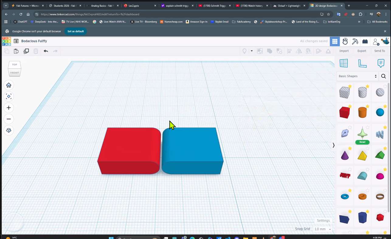
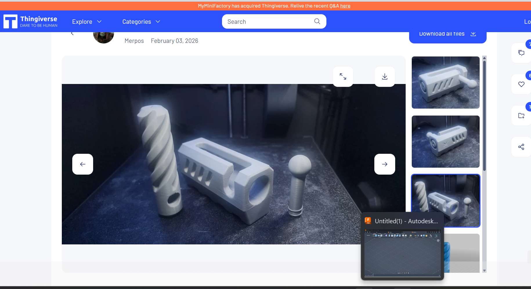
- Model an object in CAD software using free model and i redesigned to meet the none substractive requiremen and its here
tinkersCad https://www.tinkercad.com/
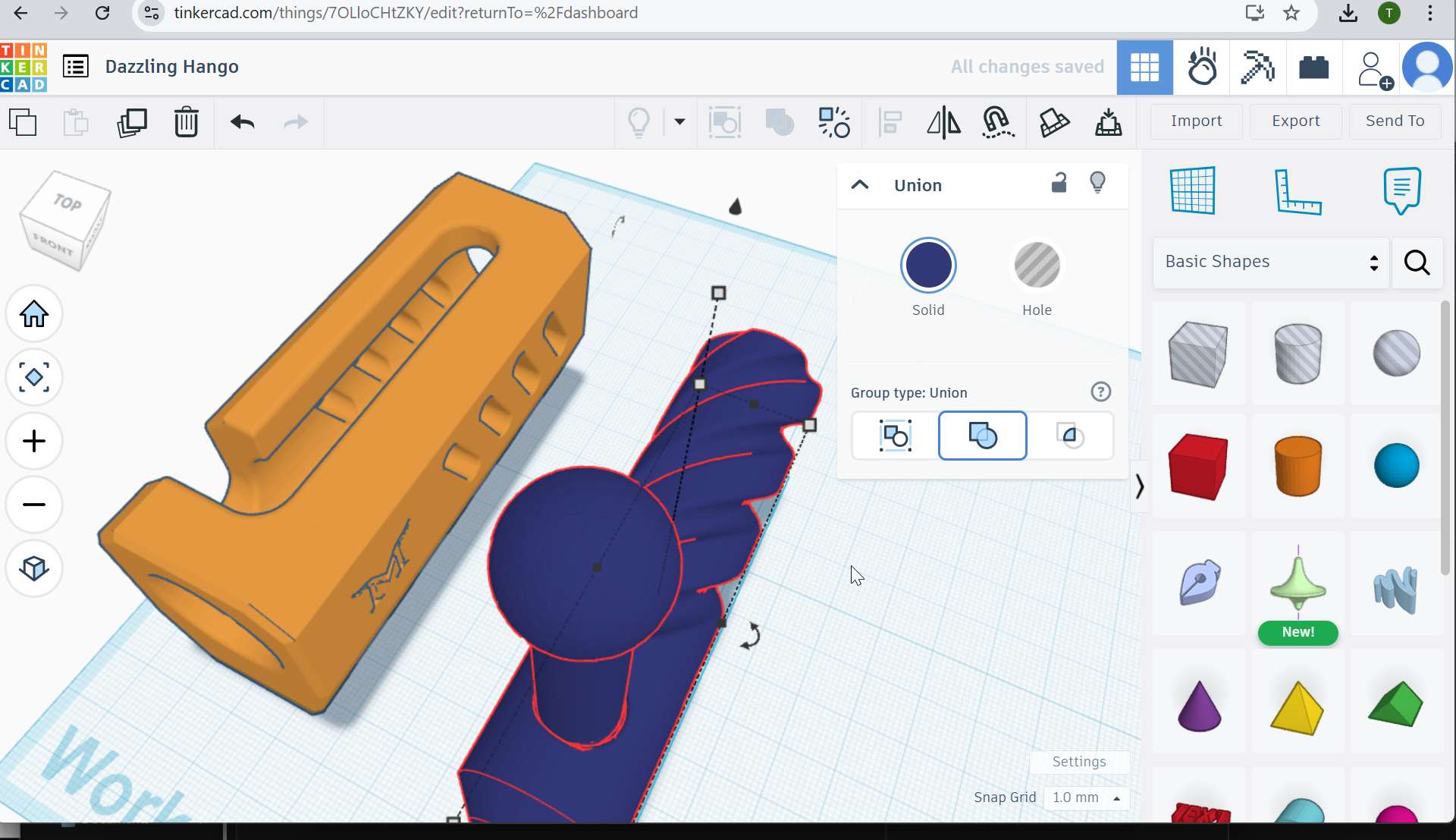
- Designed internal cavities and complex features that cannot be made with substactive methods
- Checked wall thickness and clearances and neccessary printing steps
 Source: alt text
- Modification to additive only methods for manufacturing it

3. Export File
- Exported model as .STL
- Verified mesh quality
4. Slicing
- Imported STL into slicer
- Adjusted:
- Layer height
- Infill percentage
- Print orientation
- Support settings (if needed)
- Applied design rules identified in group assignment
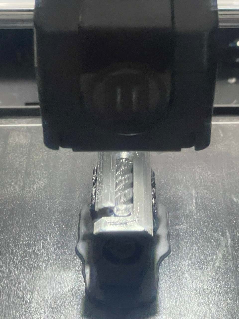
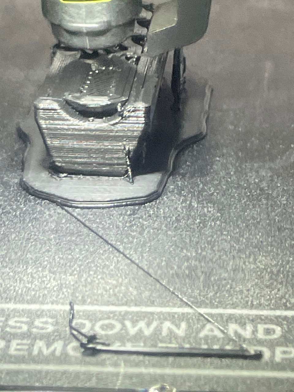
5. 3D Printing (on progress) — now done
- Printed using MakerBot Sketch
- Ensured print time within allowed limit
- Removed supports and cleaned model
## Final printed is:
Non subtractive printed, complexity: Spiral inner structure and once printed without assembling for moving part.
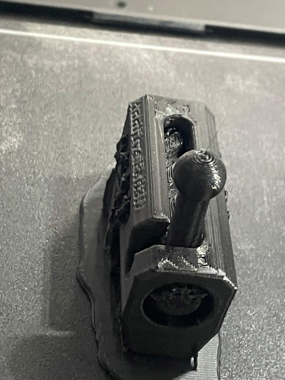
Problem and issue faced, the printed design was more complex and the pin brocken during pushing to try its slide inside. The issue was low infill density and needs support in design for that pin.
After a feedback I design my own and print with Makerbot
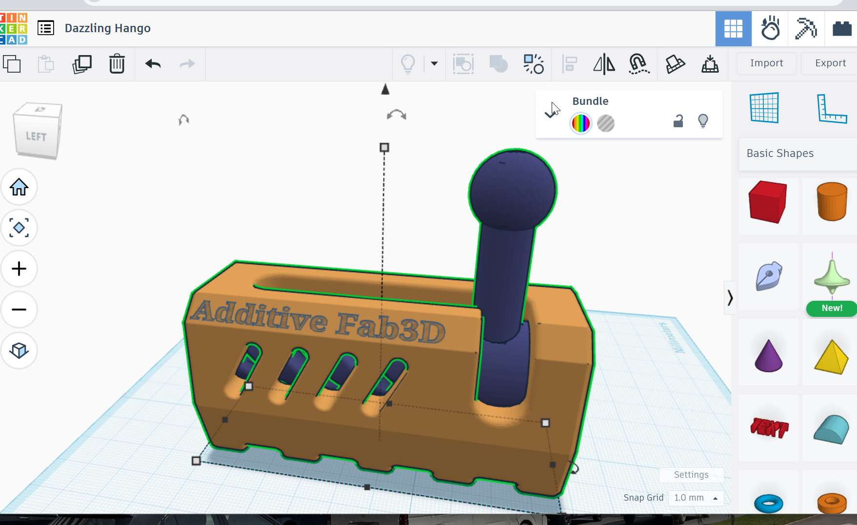
The concept I wanna define is the product to be printed that is not easily done with subtractive method. I include two letter growing up with the fabacademy as the foundation for me. The same step defined above in thinker cad followed but the object is the new one.
Open tinkercad and new document then please boxes and letters then arrange and design as i want
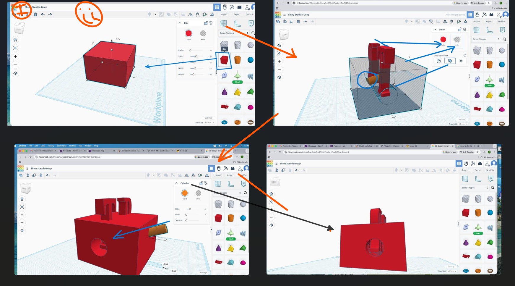
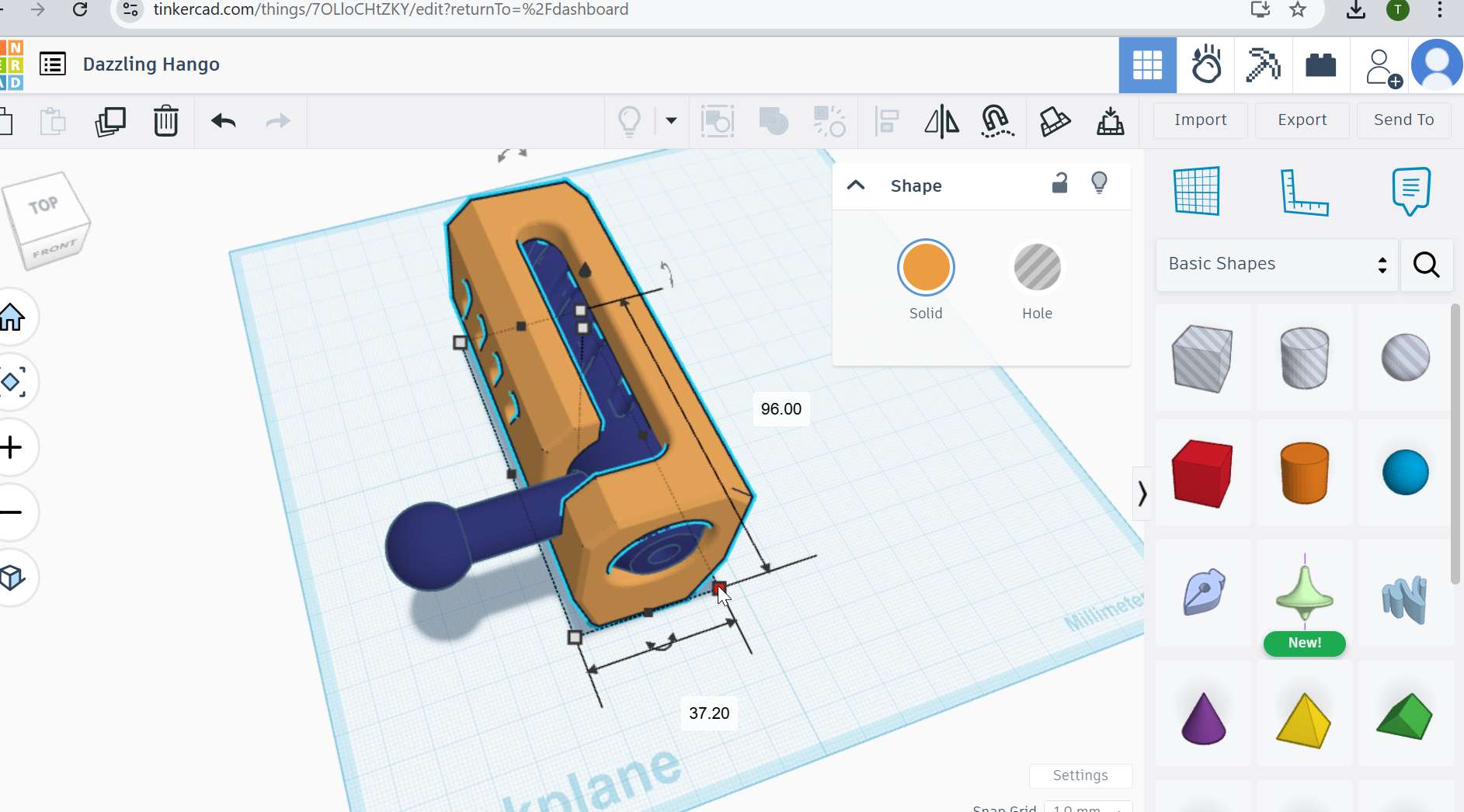
Then exporting to .stl file for slicing to the specific setup and 3D printers i wanna use
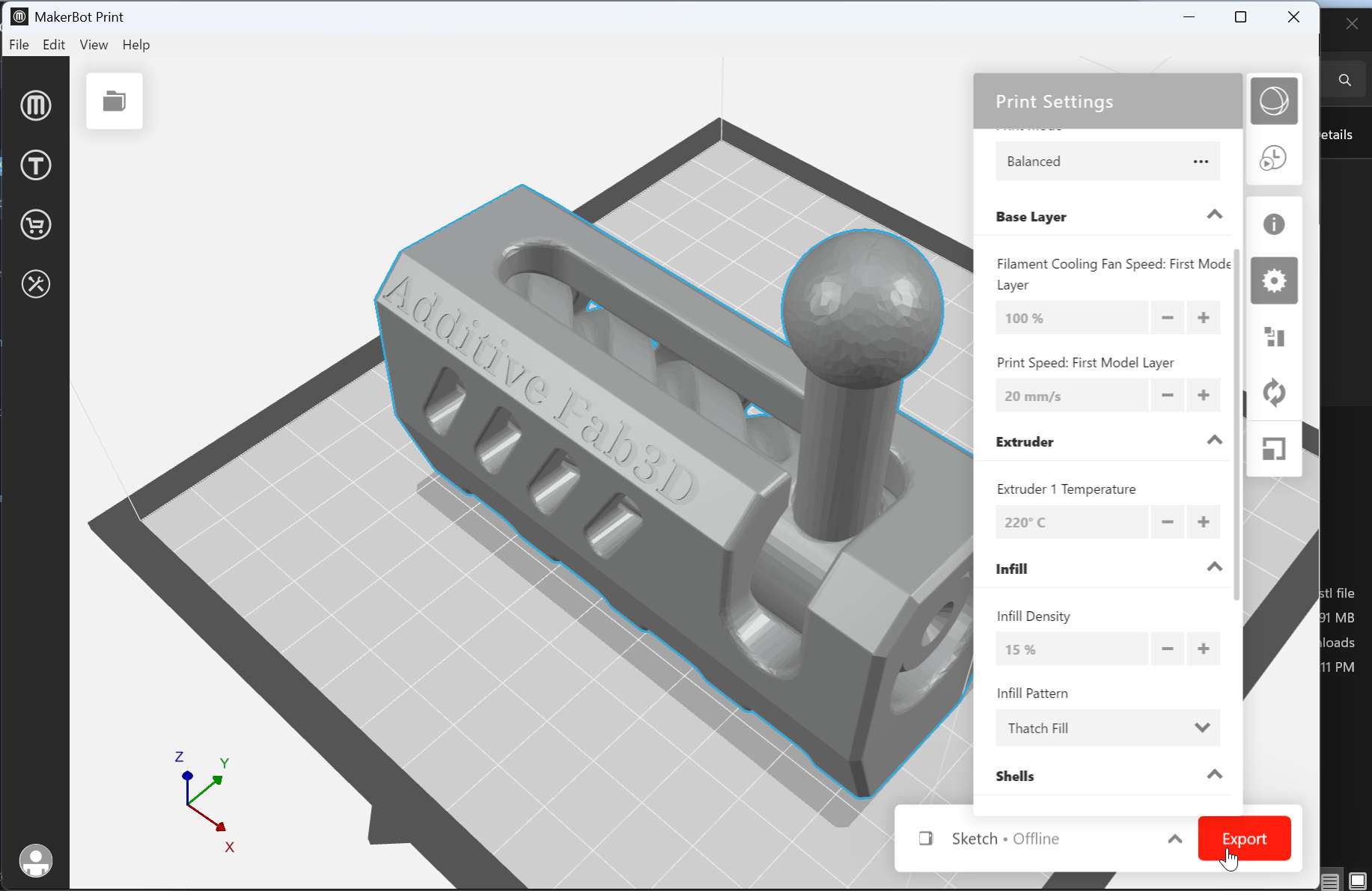
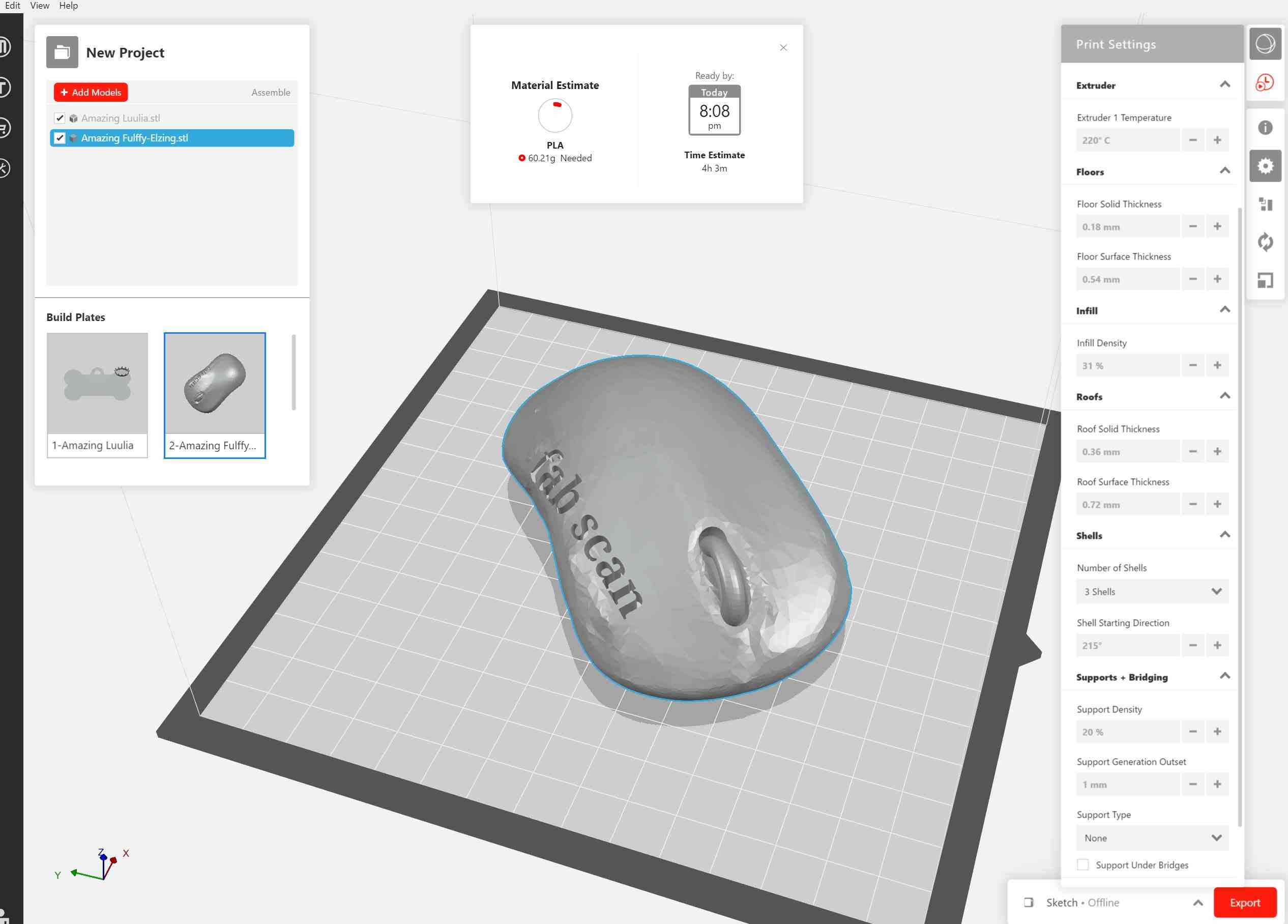
in my case Makerbot sketch mini the picture show my setup for infill (30%), material selected - PLA, floor thickness, layers -3 optional here but durability increase as the layers increase… the default value is good here but for custom print it can be changed as i wish
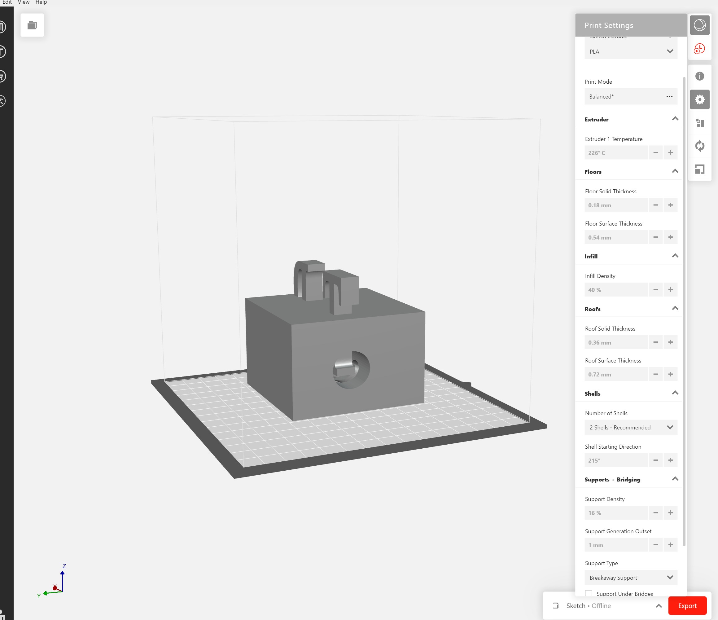
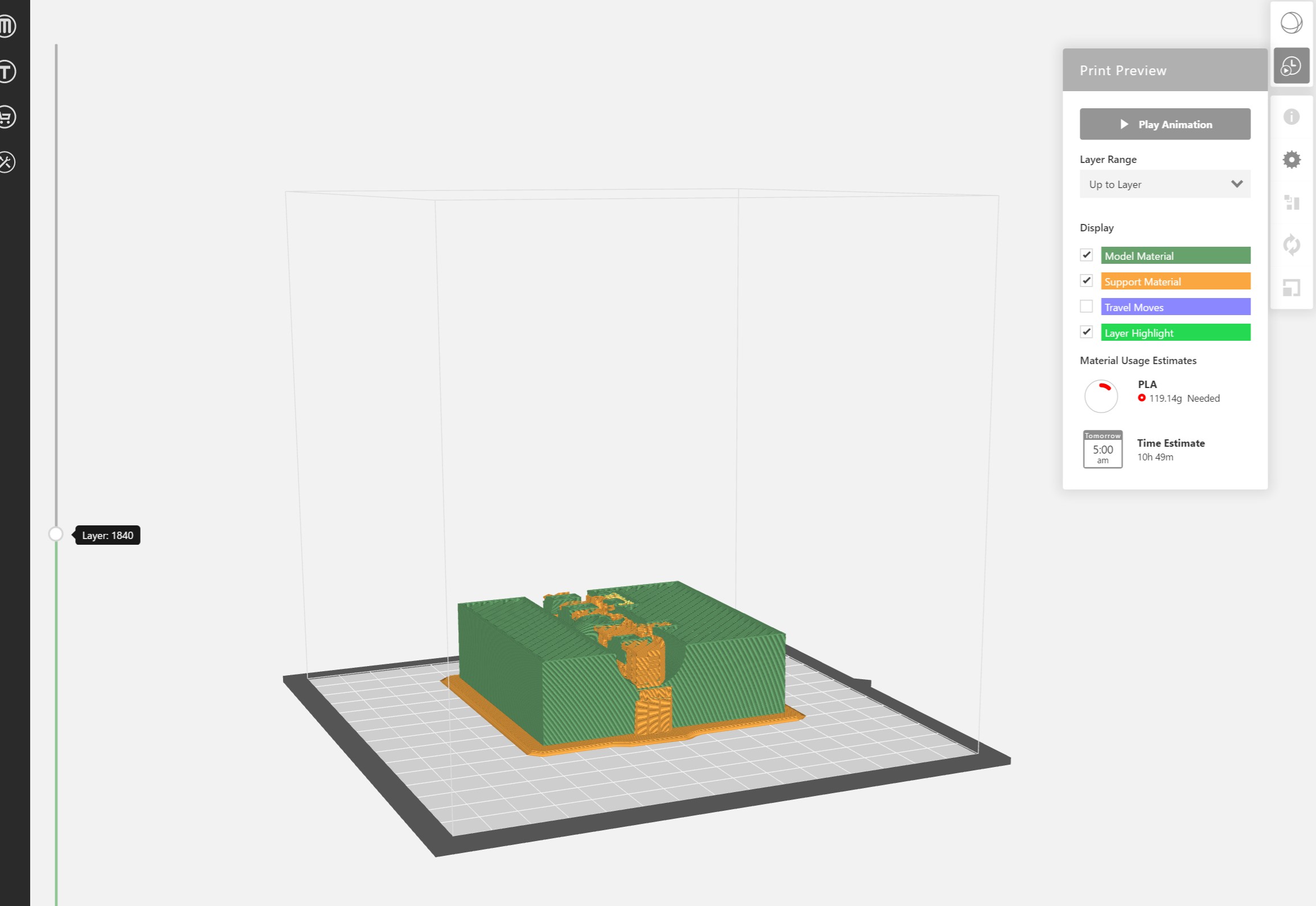
Section view to see the complexity 👇
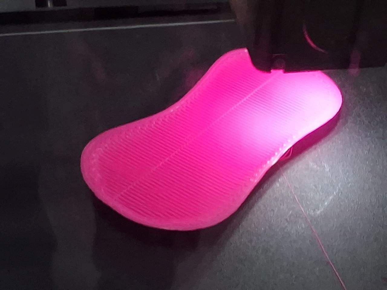
Final printed one
With expected medium complexity and density …
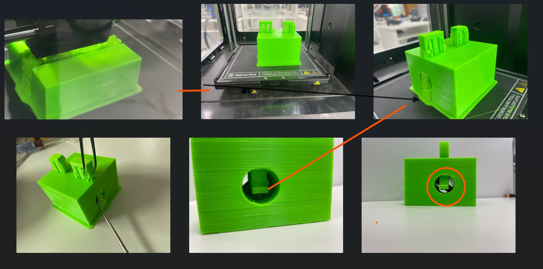 newer version
3D Scan an Object and (0ptional) Print It
Learning Outcomes
- Proper scanning techniques
- Mesh editing and repair
- Difference between CAD model and scanned mesh
- Reverse engineering basics
Digitize a physical object using 3D scanning and prepare it for fabrication. The week focused on understanding different 3D scanning methods, processing and cleaning scanned models, optimizing mesh files, and preparing designs for fabrication using slicing software.
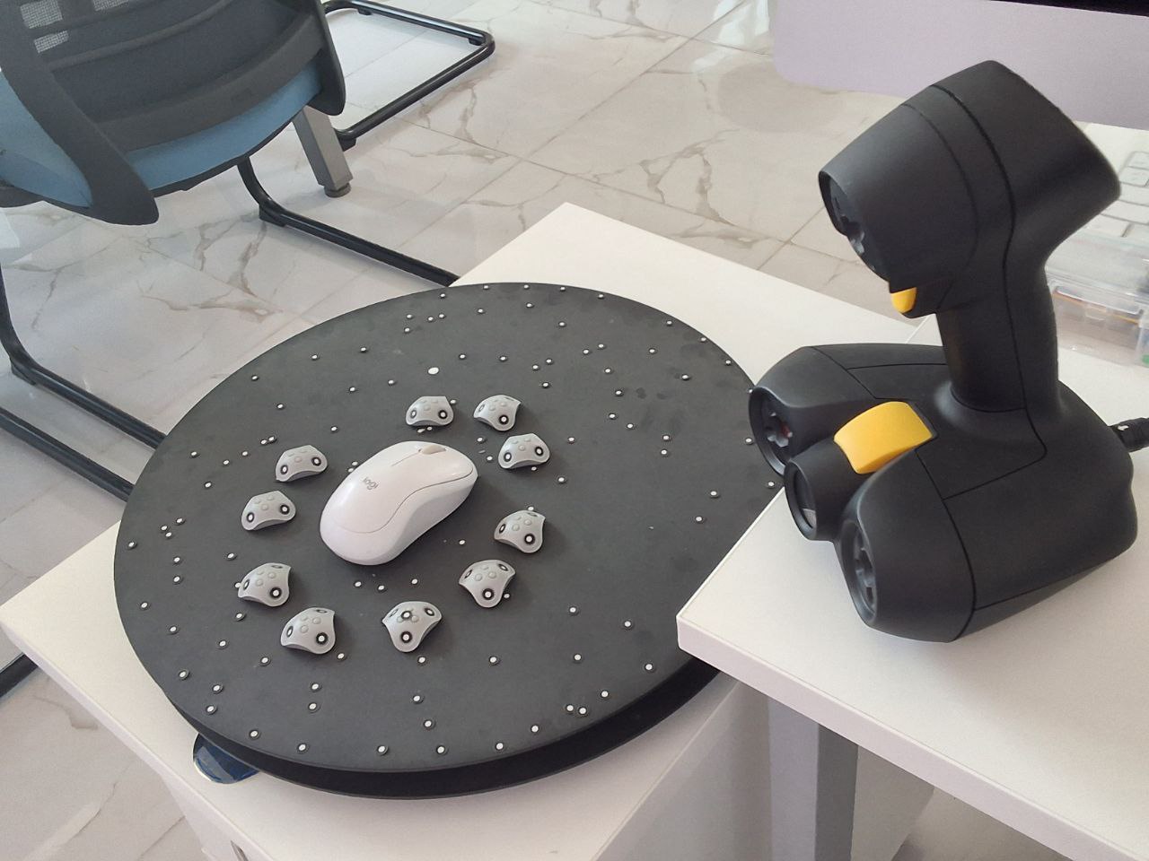
Scanning my PC mouse
I scanned using Peel3D scanner and the tool is licensed for peel.
Peel 3D Scanner Overview
The Peel 3D scanner is a professional handheld device designed to simplify the scanning process while maintaining good accuracy and usability. It is widely used in education, product development, and reverse engineering workflows.
- Handheld and portable design for flexibility
- Simple plug-and-play setup with its own peel platform
- High-resolution geometry capture
- Ability to capture color textures
- User-friendly Peel 3D software interface
Applications of Peel 3D Scanning
Peel 3D scanning is used across multiple fields due to its flexibility and efficiency.
- Reverse engineering for recreating and modifying existing parts (for d/t purpose including for startups in the center)
- Quality inspection by comparing scanned data with CAD models
- Medical applications such as prosthetics and body scanning
- Educational use for hands-on engineering learning
- Cultural heritage preservation through artifact digitization
Advantages and Limitations
Like any technology, Peel 3D scanning has strengths and constraints that must be understood.
- Easy to use and beginner-friendly
- Portable and flexible for different environments
- Accurate for small to medium-sized objects
-
More affordable than industrial-grade scanners
-
Performance may be affected by reflective or transparent surfaces
- Requires steady hand movement during scanning
- Limited effectiveness for very large objects
Step-by-Step Process
Scanning
- Before pulling the trigger, I did prepared the environment and the object:
- Target Placement: For objects with smooth, featureless surfaces, apply adhesive positioning targets (retro-reflective dots). The scanner uses these to maintain its position in 3D space.
- Surface Treatment: If the object is transparent (glass), very shiny (chrome), or deep black, spray it with a temporary matte powder (like AESUB) to allow the structured light to bounce back correctly.
- Calibration: If the scanner has been moved or experienced temperature changes, perform a quick calibration using the provided calibration plate to ensure dimensional accuracy.
- Captured multiple angles
- Ensured full surface coverage
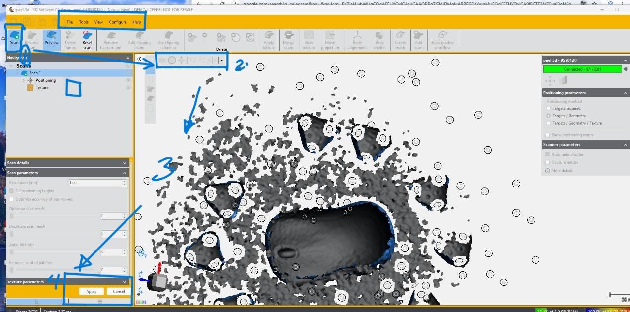
Working Principle using peel 3D
I used the Peel 3D scanner primarily to operates using structured light technology it has. It projects a known pattern onto the surface of an object, and cameras capture how the pattern deforms across the geometry. The system processes this deformation to reconstruct the object’s shape digitally.
- Projection of structured light onto the object surface
- Capture of pattern deformation using cameras
- Conversion into point cloud data
- Transformation of point cloud into mesh models such as STL or OBJ
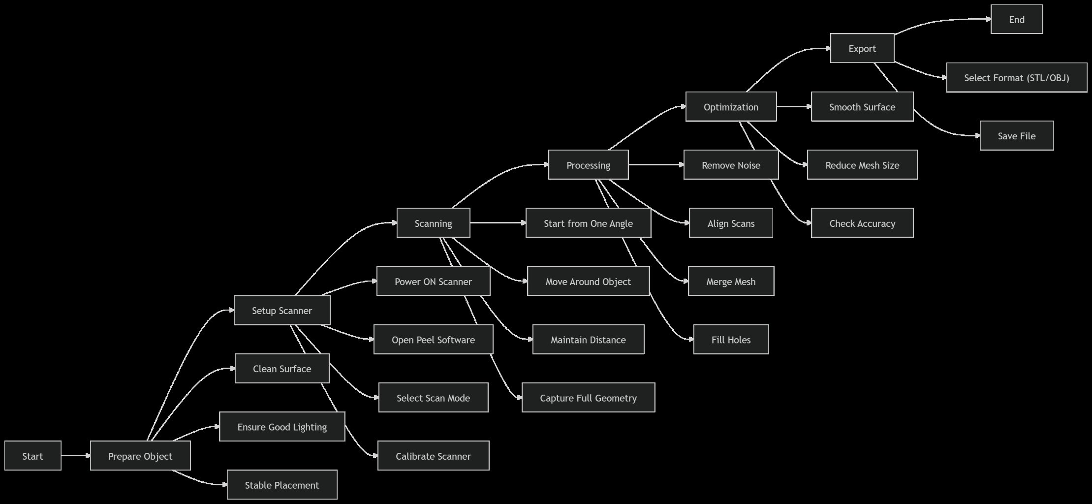
Scanning Process Workflow
The scanning process involves several stages that must be carefully followed to ensure high-quality results.
- Preparation involves cleaning the object, ensuring proper lighting, and applying markers if needed
- Setup includes connecting the scanner, launching software, and selecting appropriate scan modes
- Calibration ensures accuracy using a calibration board
- Scanning requires smooth movement and consistent distance while covering all object angles
- Post-processing includes removing noise, aligning scans, and generating the final mesh
- Exporting allows saving the model in formats such as STL, OBJ, or PLY
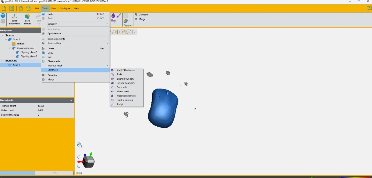
Mesh Cleaning
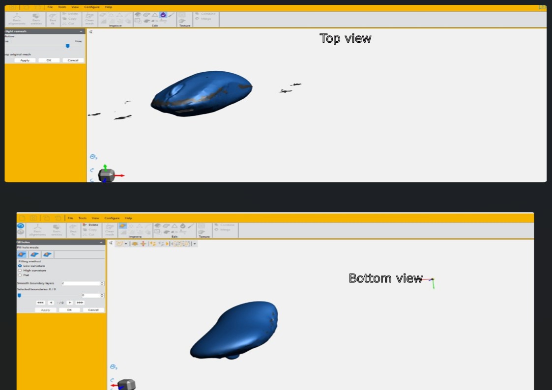
- Hole Filling:
- Flat Fill: Best for small holes on flat surfaces.
- Curvature Fill: Uses the surrounding geometry to “predict” the curve of the missing area (essential for organic shapes).
- Smoothing & Decimation:
- Smoothing: Removes “digital noise” or roughness from the surface.
- Decimation: Reduces the triangle count in flat areas while keeping detail in complex areas, making the file easier for other software to handle.
- Fixing Mesh Errors: * Remove Isolated Patches: Deletes tiny clusters of triangles that aren’t connected to the main body.
- Bridge/Stitch: Manually connects two open edges that should be joined.
- Normal Correction: Ensures all triangles are “facing” outward so the software knows what is the inside and outside of the object.
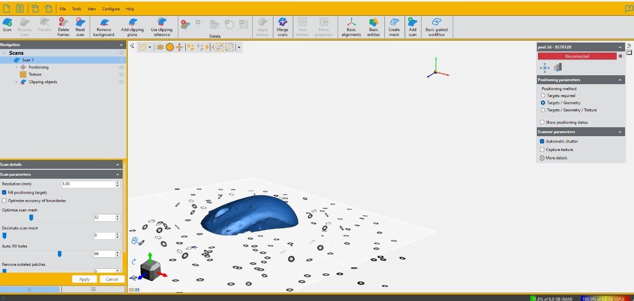
Final Image of my scanning job
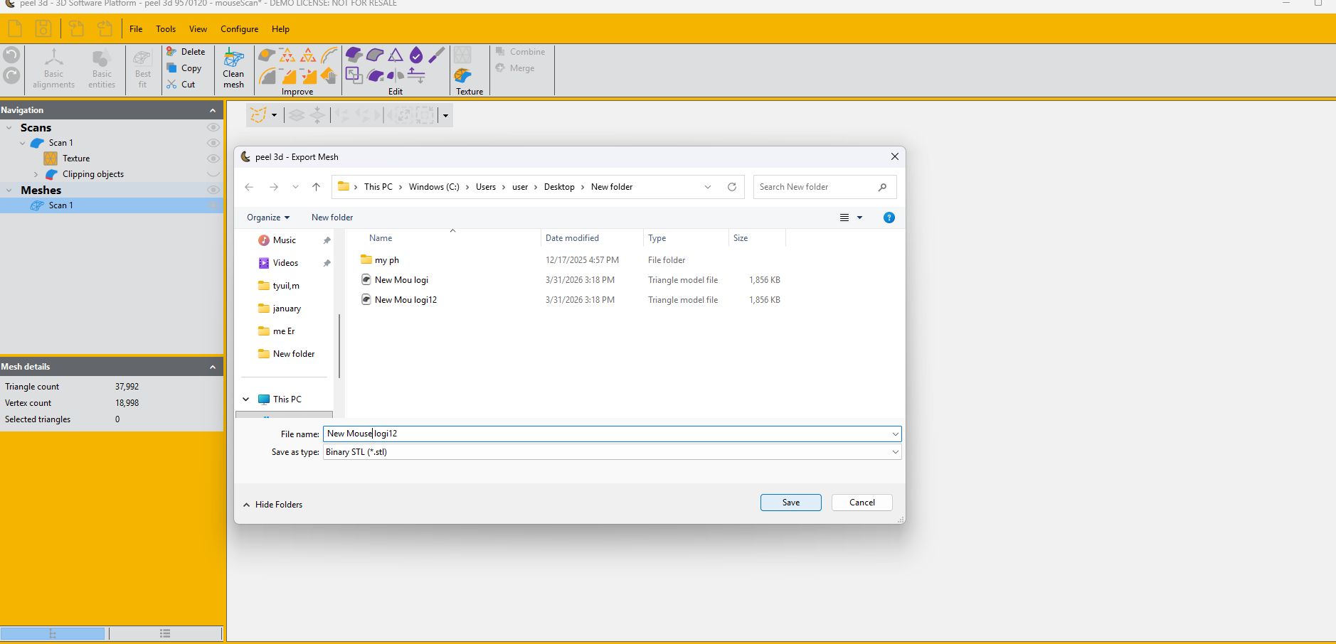
3. Export
Once the mesh is “watertight” (no holes) and repaired, I export the file. Common Formats: .STL (standard for 3D printing), .OBJ (includes color/texture data), or .PLY.
Post-processing: From here, the file is ready for a slicer (for printing) or a reverse-engineering software (like Geomagic or SOLIDWORKS) to convert the mesh into a usable CAD model.
4. Optional Printing
-
Prepared file in slicer
-
Compared printed model with original object. This is Scanning my PC mouse with Peel scanning and then import to tinker to add text and more dimension check.
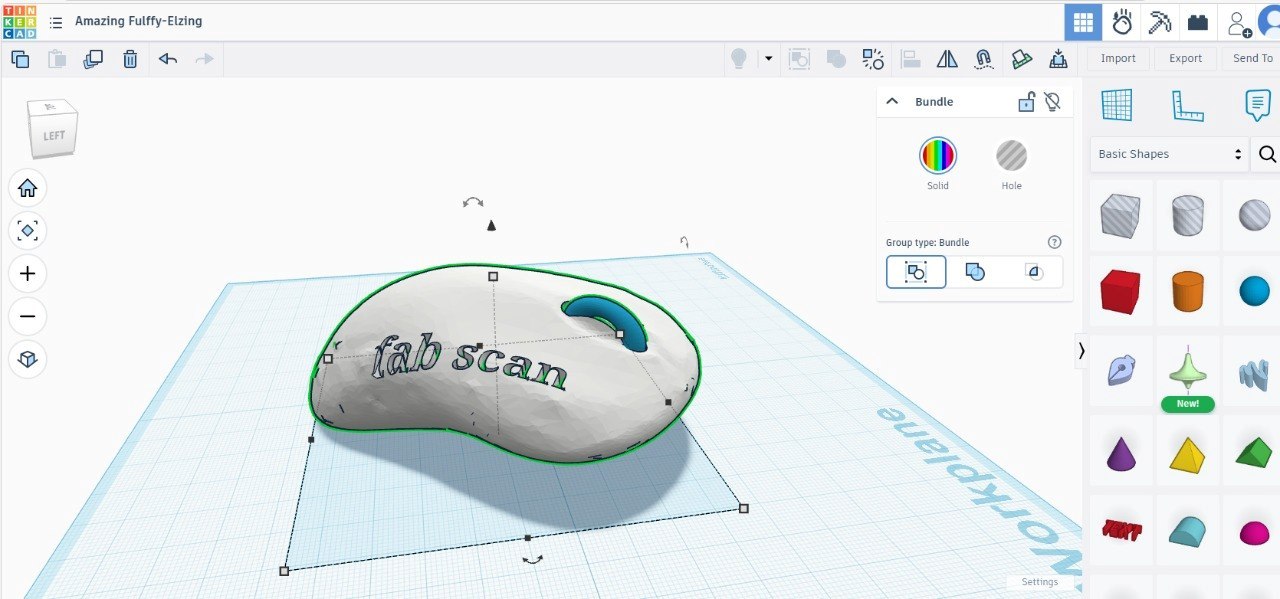
- export to .STL and slice in 3D printers SW
-
Printed using MakerBot Sketch
-
On printing
Problem Faced
Error in the finalizing was due to peel software license and difficulties I Faced to print that the peel stack too many times to finish mesh....print soon updating my license issue to print it. Now corrected and printed after scanned
Solution
updating the firmware and reconnecting the scanner… it is outo updating but sometime stack due to low connectivity. After updating and fixing the license activation by go to Software manager, the software became stable, allowing the scan to be finalized successfully. The model was then processed and printed without further issues. Reconnect all the charger and cables again may needed 🫢
Design Files
Week05 References
AI: Gemini used as prompt “Peel 3D Scanning: Full Process Description”