Week03 Computer-Controlled Cutting
Weekly Focus
This week focused on computer-controlled cutting, specifically:
- Laser Cutting
- Vinyl Cutting
- Parametric Design
- Press-Fit Construction Kits
The objective was to understand how parametric design techniques can be used to create adaptable designs that respond to material thickness and laser kerf.
Assignment Overview
The assignment required:
- Designing and fabricating a parametric press-fit construction kit
- Accounting for material thickness and laser kerf
- Producing a vinyl-cut design
- Documenting the full workflow
The laser cutter characterization and kerf testing were completed as part of the group assignment.
See group documentation: Group Assignment – Laser Cutter Characterization
Individual Assignment
Parametric Press-Fit Construction Kit
A press-fit kit is a construction system where parts connect without glue, screws, or fasteners.
The stability of the structure depends entirely on accurate slot dimensions and friction between parts.
To make the design flexible and reusable, I used parametric design techniques so that the slot width can be easily modified if the material thickness changes.
Parametric Design Method (this method is changed to Fusion360 parametric… Rico recommended to use as requirement in the assignment… I used it in the following)… just this was my error
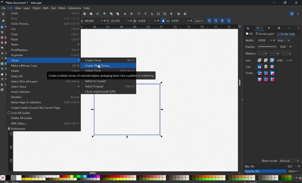
Instead of manually editing every slot, I created a master notch in Inkscape (not allowed… this was my mistake … Using Freecad or Fusion 360 is allowed).
The workflow:
- Create a single master notch representing the slot width
- Place it on a separate layer called
Notch_Template - Generate slots using Edit → Clone → Create Clone
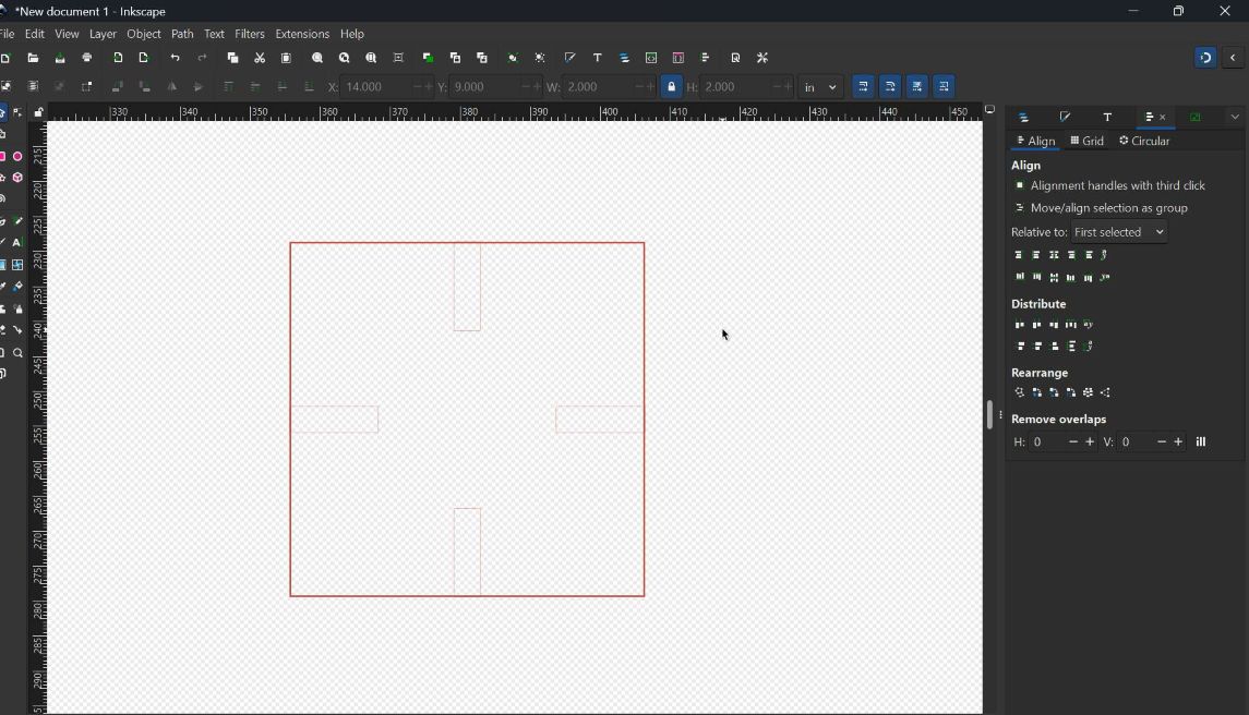
- Position slots using Align and Distribute
With this method:
- Changing the master notch width
- Automatically updates all slots
This is the core concept of parametric design.
Parametric Design Reference
Video used for learning the technique:
Inkscape Parametric Design Channel: Young Engineers Of Today
https://youtu.be/ErelrIJxZ6I
Key concepts demonstrated:
- Master notch creation
- Clone-based parametric design
- Align and distribute workflow
- Scalable parametric layouts
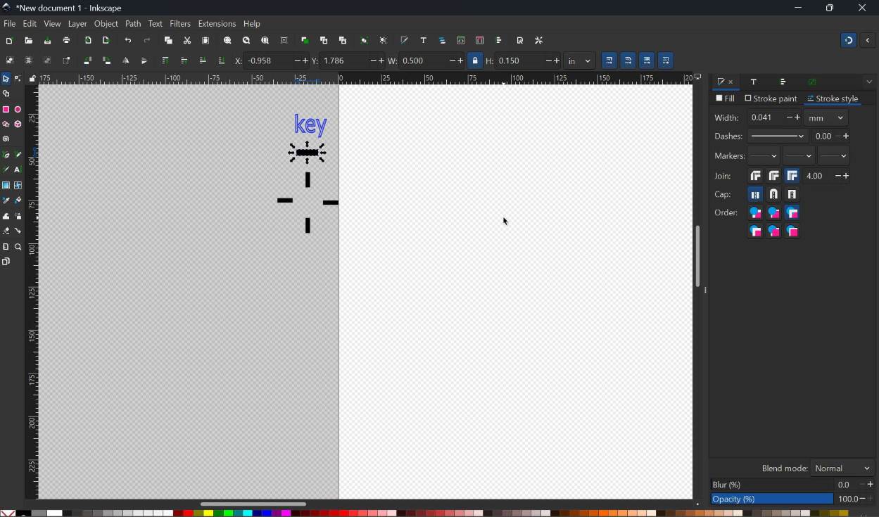
Clone setup
 Clone control
 Clone keys
Computer-Aided Design (Parametric Design with Fusion 360)
Assignment Overview
In this section of the assignment i focussed on parametric design using Autodesk Fusion 360.
The workflow was updated from Inkscape to Fusion 360 based on instructor feedback to achieve true parametric modeling.
The goal is to design a structure where all parts automatically update when a parameter is changed.
Software Used
- Autodesk Fusion 360 (Parametric CAD)
What is Parametric Design?
Parametric design uses: - User-defined parameters - Constraints - Feature relationships
This allows: - Automatic updates - Design flexibility - Faster iteration
Initial Setup and User Parameters
Step 1: Create Base Component
To maintain a clean design structure:
- Create a new Component named
Base - Work inside this component
Base Component Setup
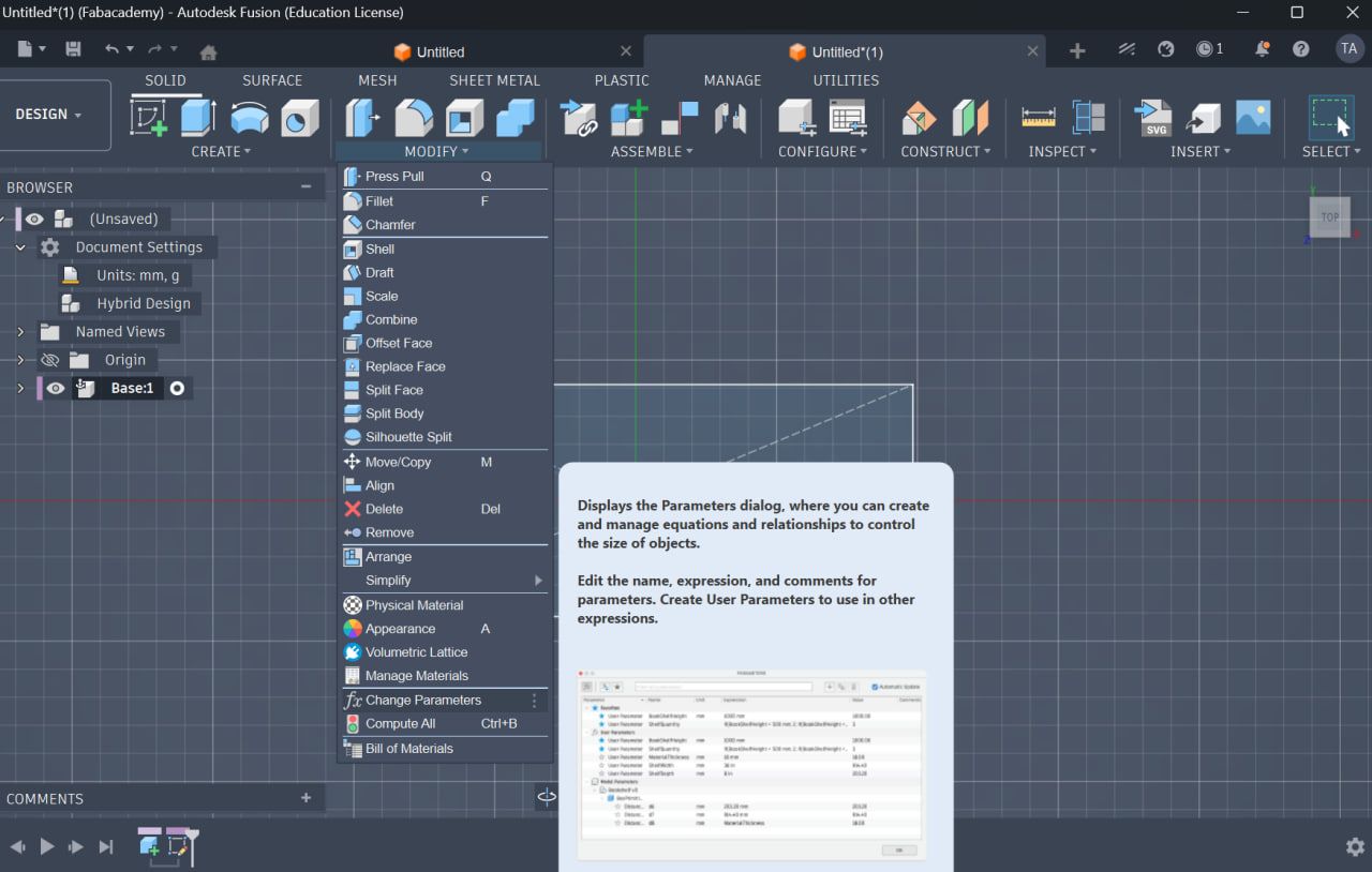
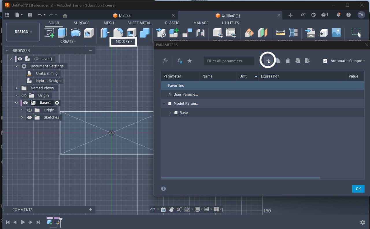
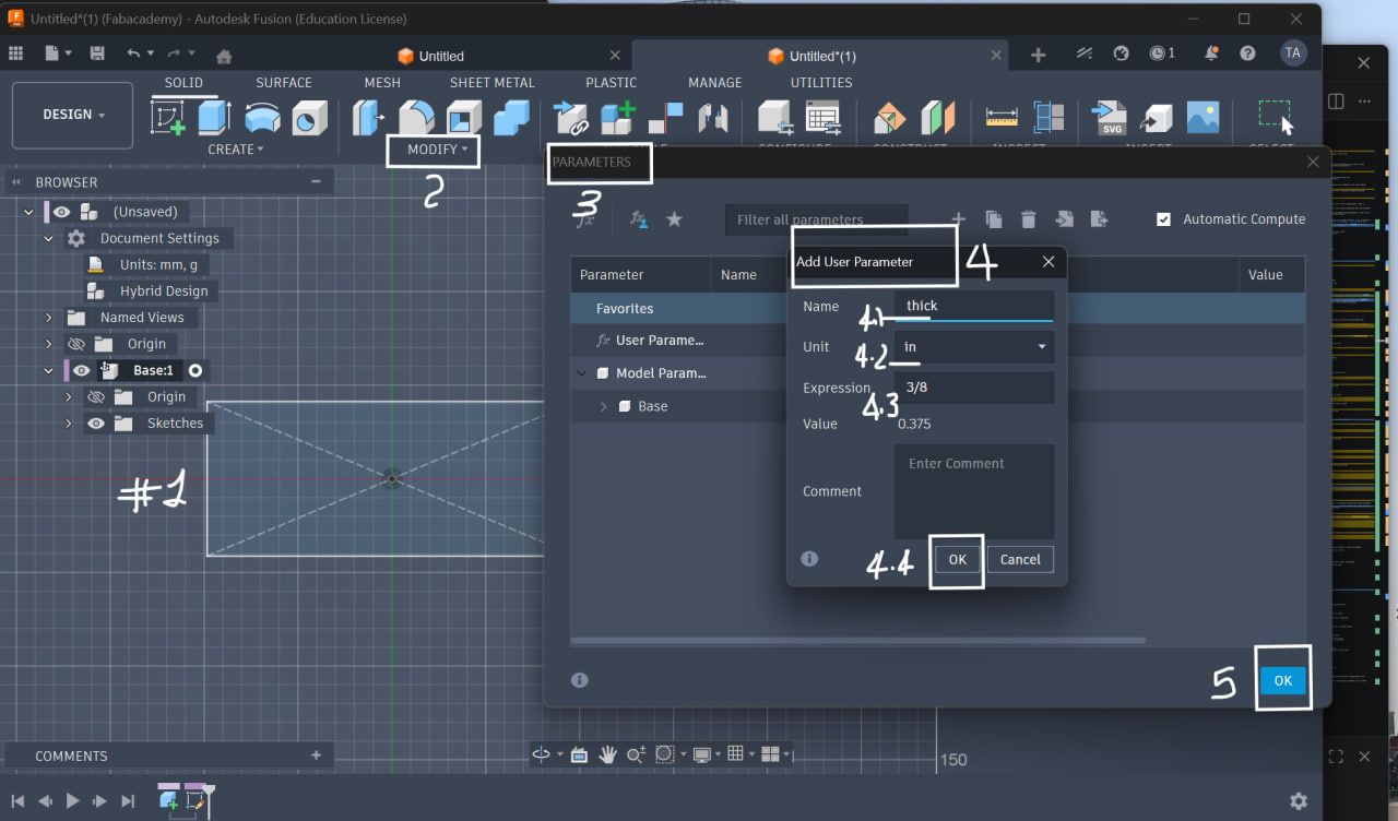
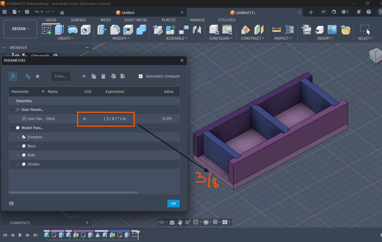
Step 2: Define User Parameters
Go to:
Modify → Change Parameters
| Name | Expression | Description |
|---|---|---|
| thick | 3/8 in (or 3 mm) | Material thickness |
| notch_width | 3.2 mm | Slot width |
| notch_depth | 10 mm | Slot depth |
| slot_spacing | 20 mm | Slot spacing |
This allows global control of the design … shown at the final here
Parameters Setup
Start parametric goto modify toolbar and extend the drop down select change parameter
Base Construction
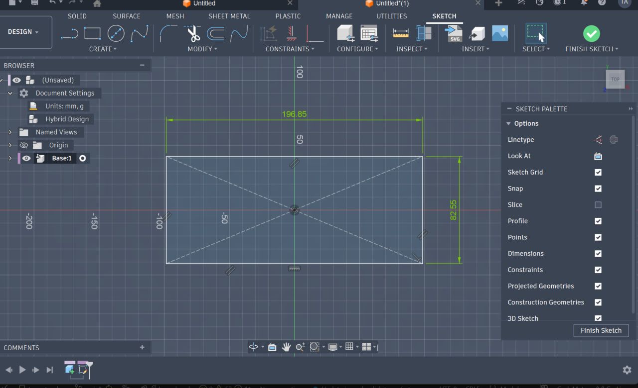
Step 3: Create Base Sketch
Base Sketch
- Use Center Rectangle (important for symmetry)
- Anchor it at the origin
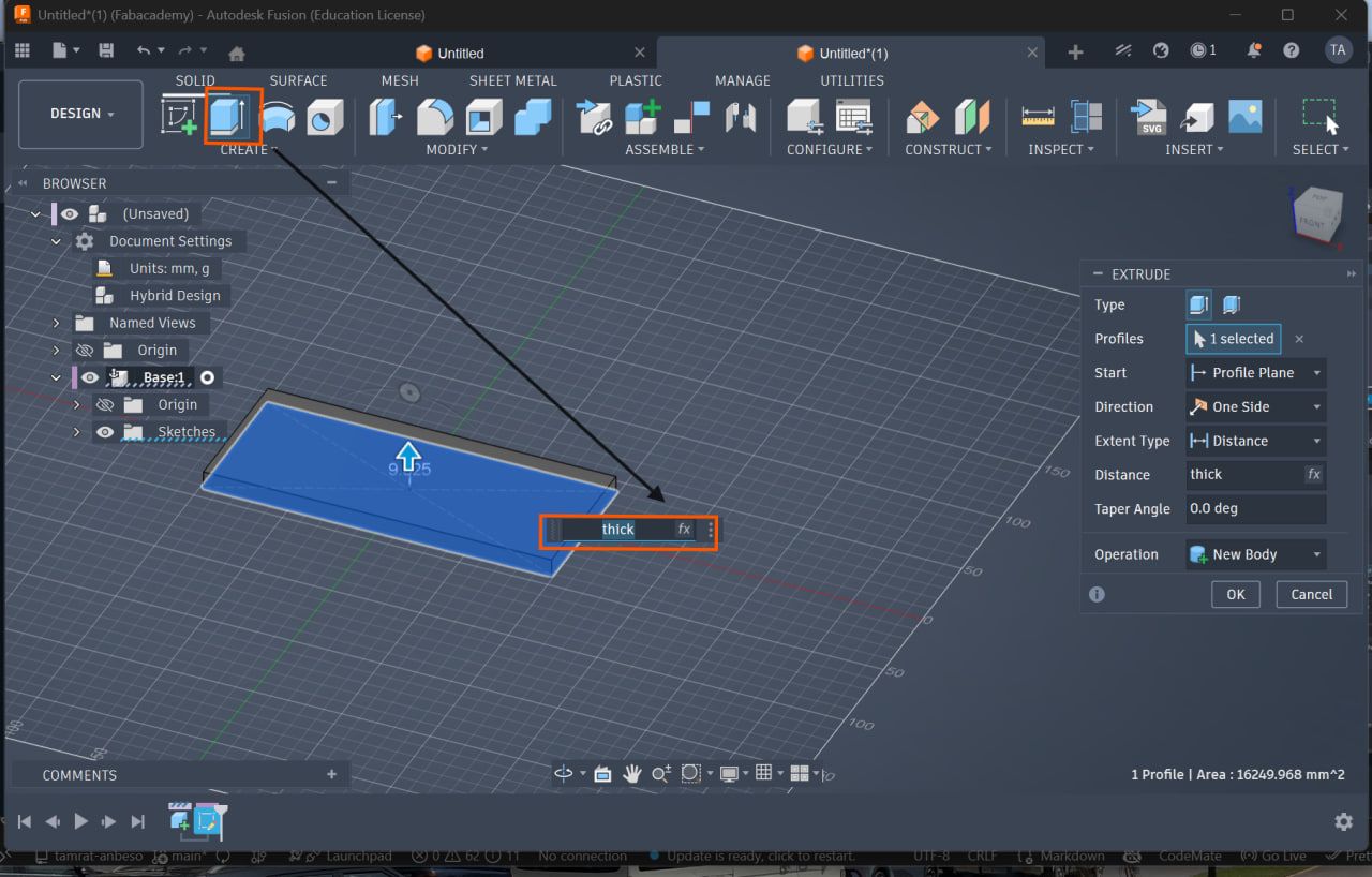
Step 4: Extrude Base
Base
- Extrude using parameter:
thick
Parametric Side Design
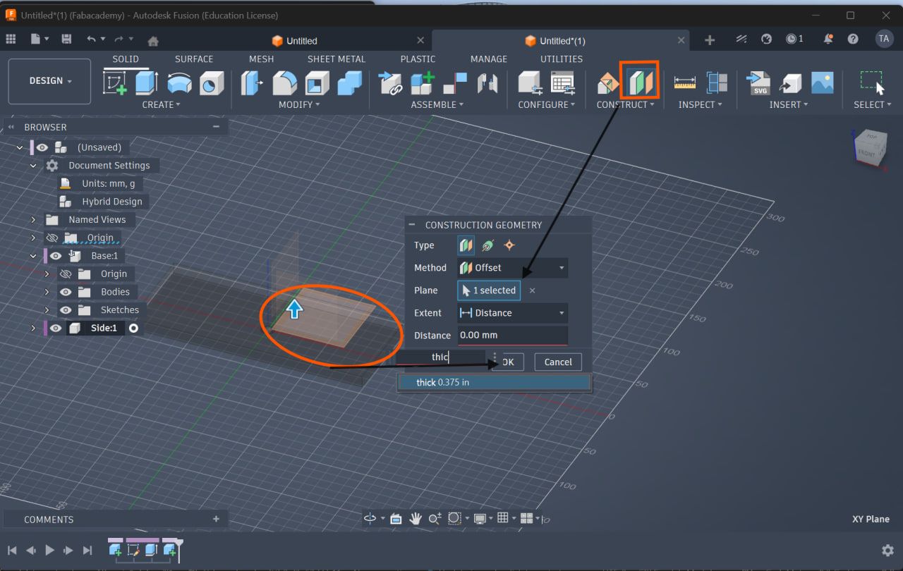
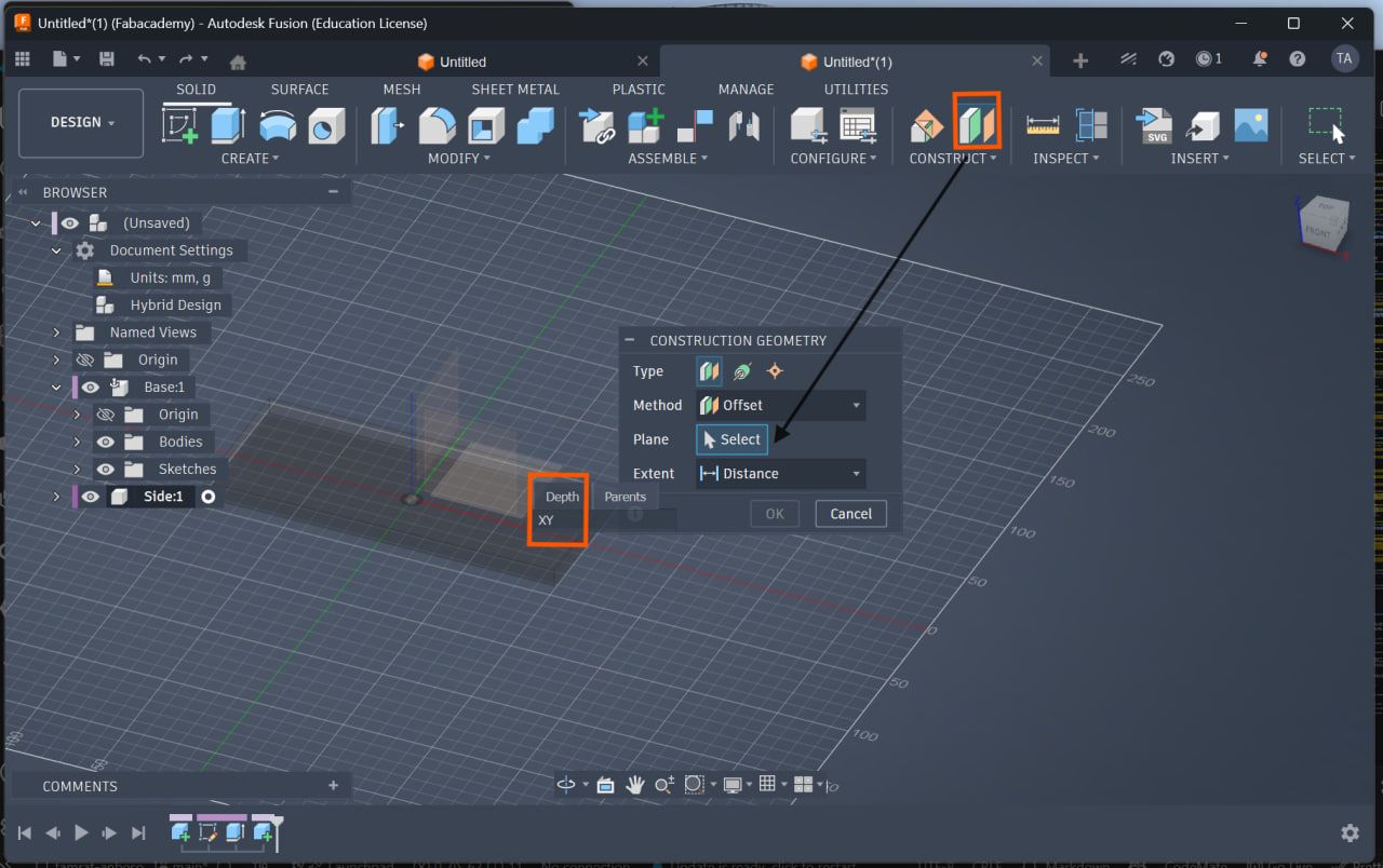
Step 5: Create Offset Plane
- Go to:
Construct → Offset Plane - Set distance =
thick
This positions the side correctly
Offset Plane
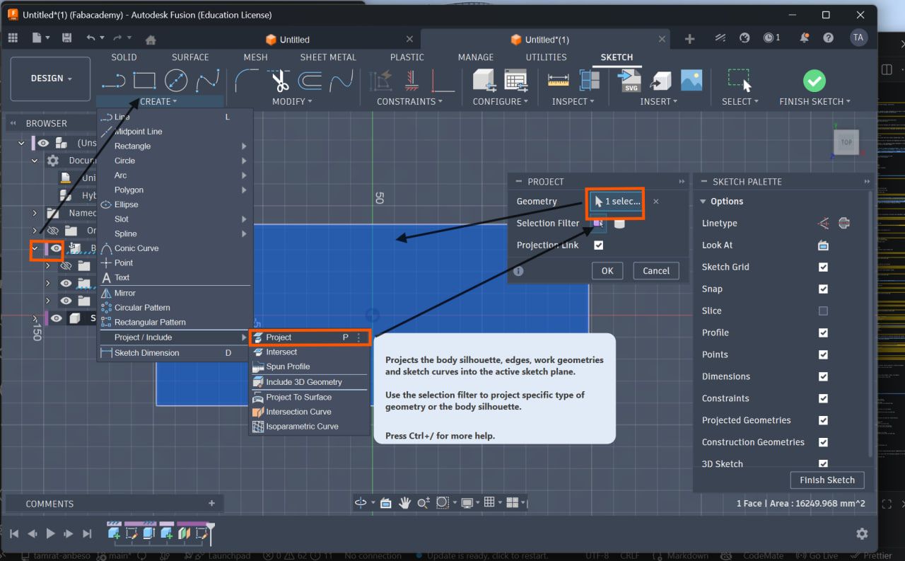
Step 6: Project Geometry
- Press
P(Project tool) - Select base edges
Ensures alignment between parts
Project Geometry
Offset firs from the tools bar and select the xy plane on the purposed body
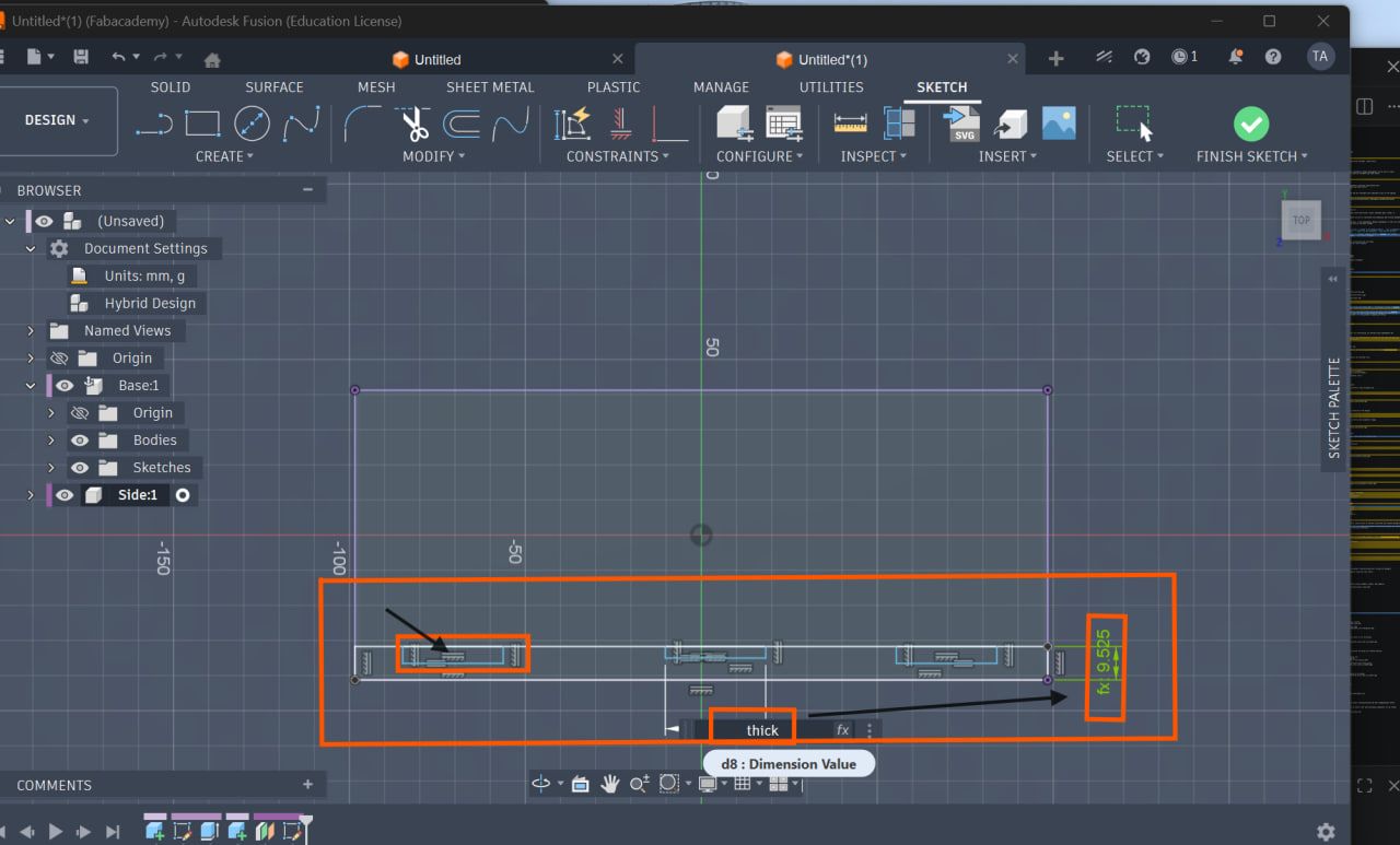
Step 7: Create Master Notch (Slot)
- Draw one notch using rectangle
- Apply dimensions:
- Width =
notch_width - Depth =
notch_depth
Master Notch
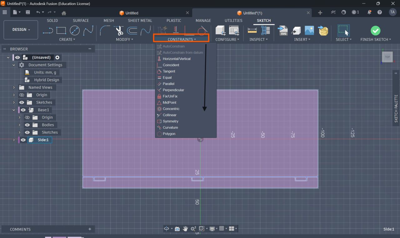
Step 8: Apply Constraints
Apply:
- Equal Constraint → uniform slots
- Midpoint Constraint → center alignment
- Collinear Constraint → edge alignment
Ensures stable parametric behavior
Constraints Applied
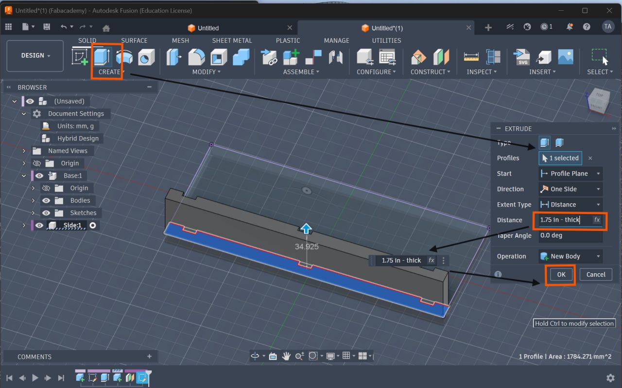
Step 9: Extrude Side (Parametric Formula)
Extrude using:
Total Height - thick
Keeps total height consistent
Side Extrusion
Mirror and Pattern Tools
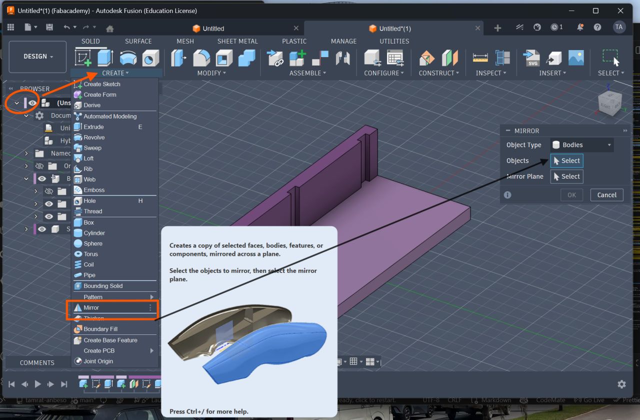
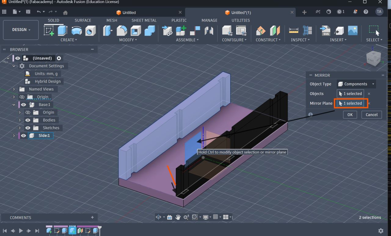
Step 10: Mirror Side
- Use:
Create → Mirror - Mirror across origin plane
To avoids manual duplication i used the mirror tool
Mirror Tool
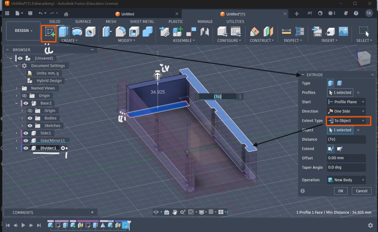
Step 11: Create Divider
- Project slot geometry
- Extrude up to top face
Divider Creation
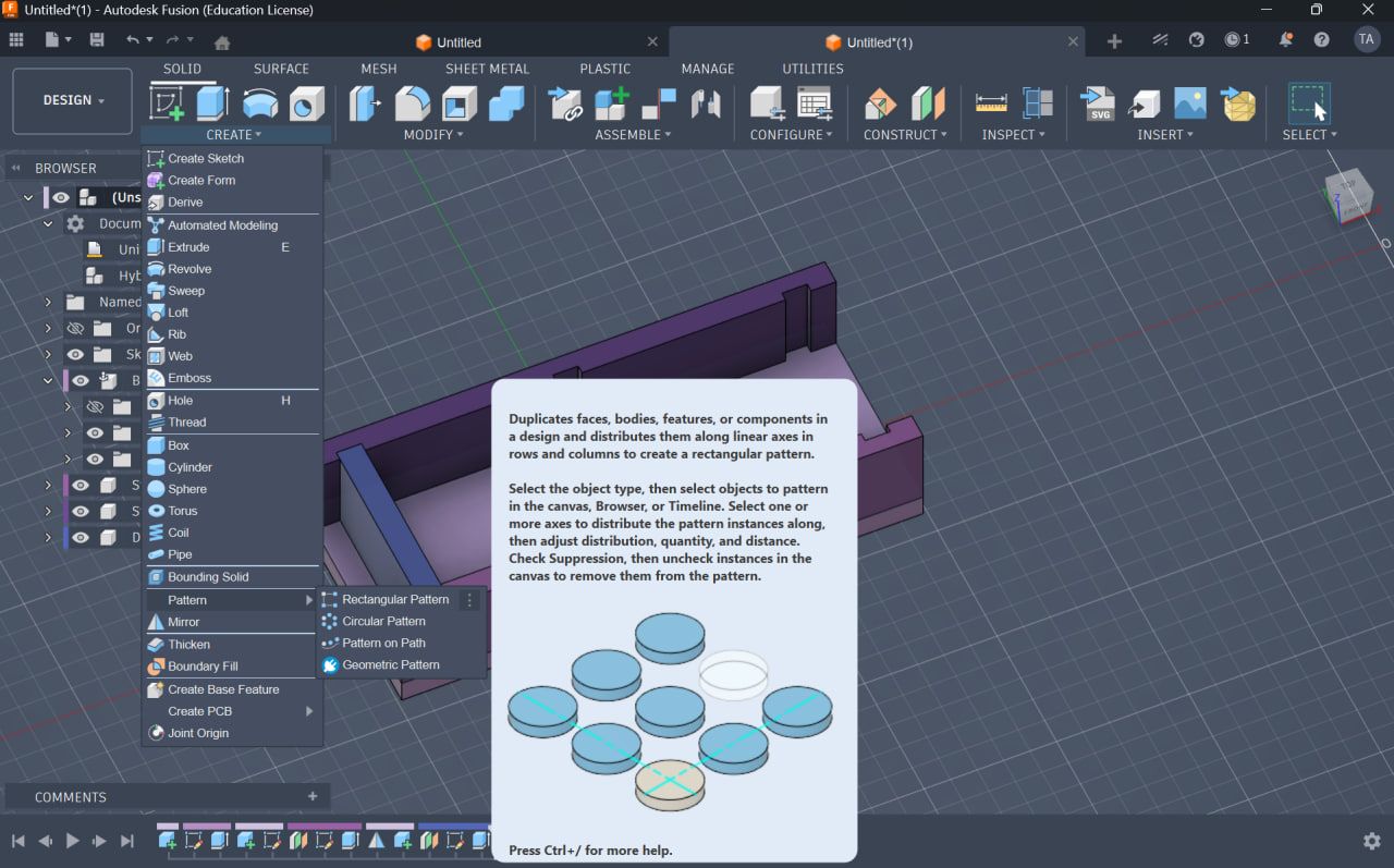
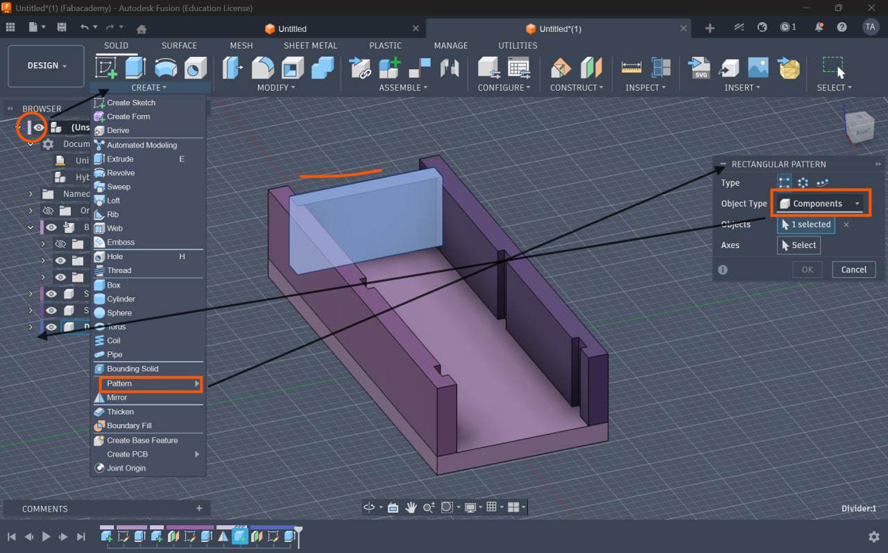
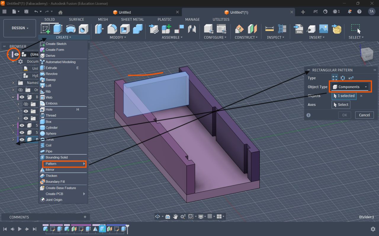
Step 12: Rectangular Pattern (Component Level)
- Use:
Create → Pattern → Rectangular Pattern - Pattern type: Component
- Extent type: Extent
Distance formula:
Total Length - (3 × thick)
Ensures perfect fit automatically
Pattern Setup
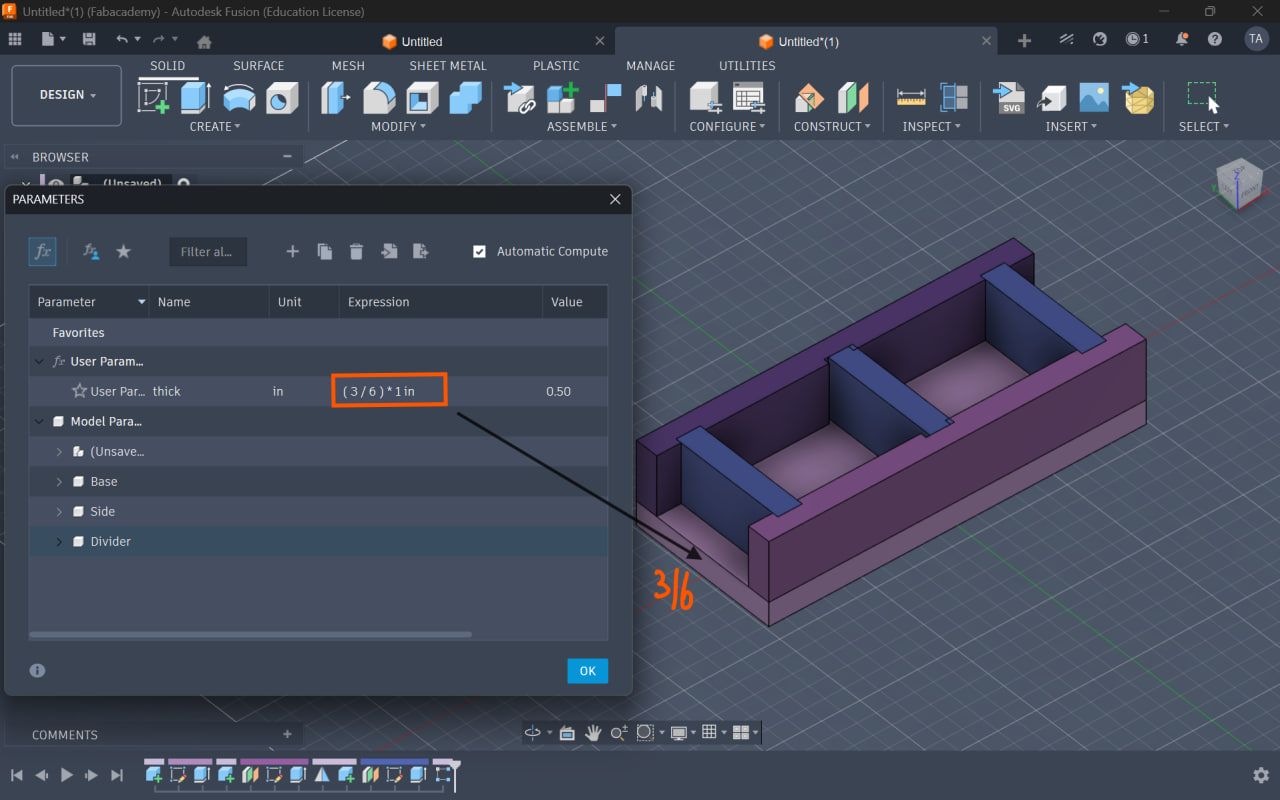
Parametric Testing
Step 13: Modify Parameters
Test by changing:
- thick
- notch_width
Parametric Result
 change only the thickness the main control for this parametric design
A with 3/8
change only the thickness the main control for this parametric design
A with 3/8
A with 3/8
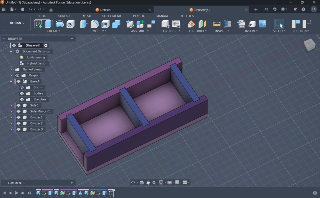
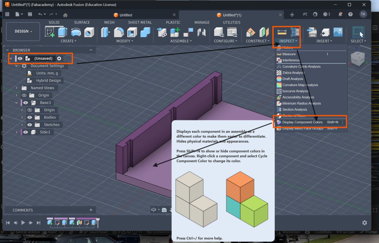
Visualization and Workflow
Step 14: Component Colors
- Go to:
Inspect → Display Component Colors
Helps distinguish parts visually and inspect with color for more clear work flow
Component Colors
Key Learning
- Parameters control entire design
- Constraints maintain geometry relationships
- Offset planes improve structure
- Projection ensures alignment
- Patterns automate repetition
- Mirror avoids redundancy
Comparison: Inkscape vs Fusion 360
| Inkscape Method | Fusion 360 Method |
|---|---|
| Clone | Rectangular Pattern |
| Manual align | Constraints |
| Static design | Fully parametric |
| Limited control | Parameter-driven |
Final result
Fusion 360 enables true parametric modeling, allowing full control over the design using parameters, constraints, and patterns.
This workflow ensures: - Accuracy - Flexibility - Easy modification
Learning Resources
Fusion 360 Parametric Design Tutorials [Fusion360 parametric tutorial]https://www.youtube.com/watch?v=zPzHMFK5ldk
Vinyl Cutting – Laptop Sticker
In addition to laser cutting, the assignment required producing a vinyl-cut design.
I created a FabAcademy logo sticker using the vinyl cutter.
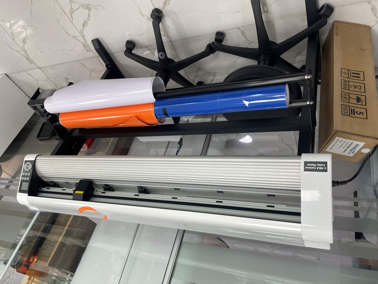
Machine Used
C-48LX Contour Cutter Plotter
The C-48LX plotter is used for cutting vinyl graphics, decals, and labels.
C-48LX cutter
Vinyl Cutter Settings
| Parameter | Value |
|---|---|
| Speed | 200 mm/s |
| Force | 90 gf |
| Blade Offset | 0.25 mm |
Vinyl Design Workflow
- Download FabAcademy logo
- Import SVG into Inkscape
- Convert shapes to vector paths
- Prepare stroke-only design
- Export cut file
- Send to cutter using SignMaster
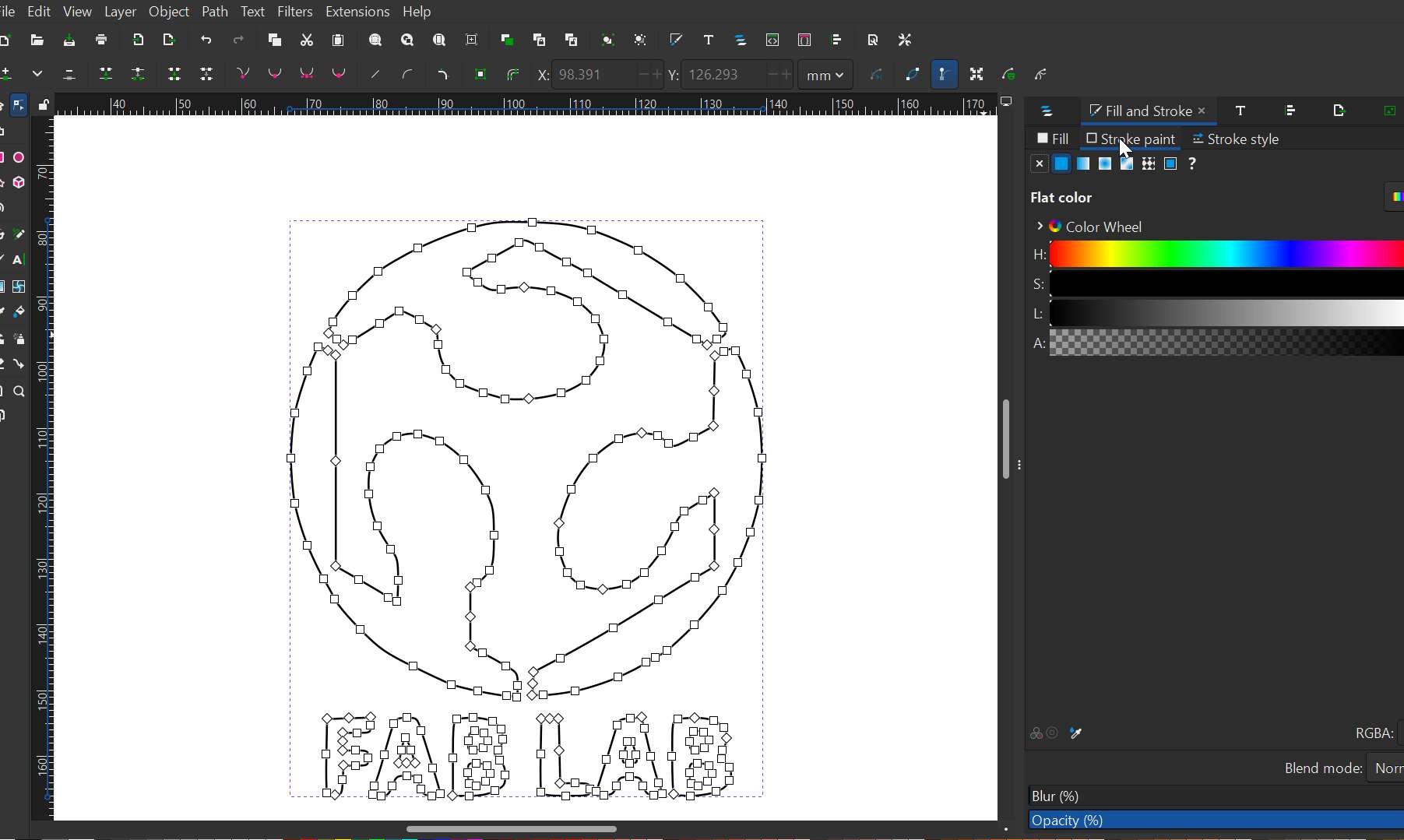
Bring the correct file Made the logo cuttable
![]()
Work on the Vector conversion of the logos
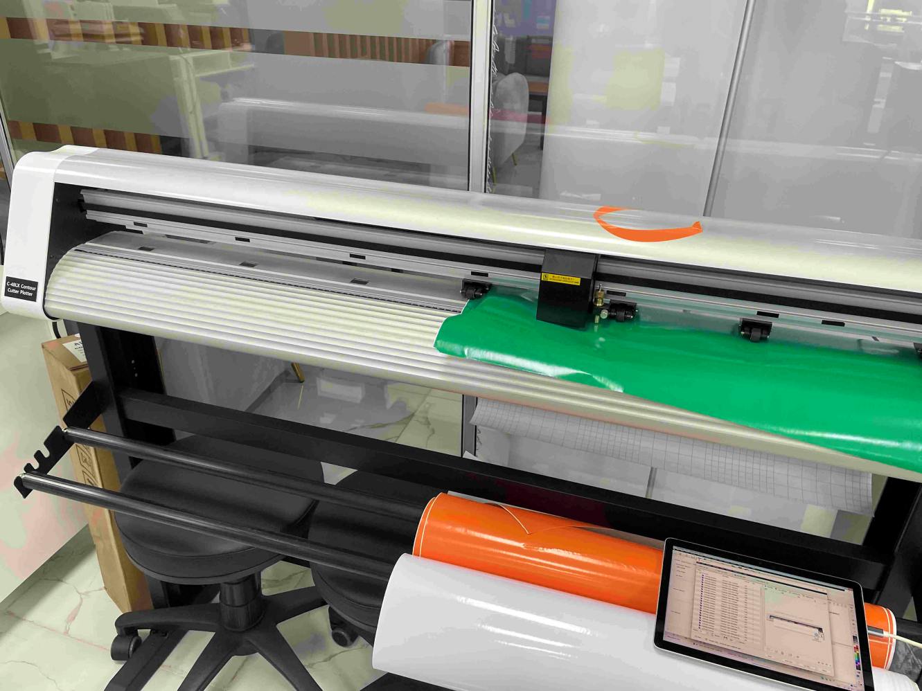
Vinyl Cutting Process
The vinyl cutter followed the vector paths to cut the design.
My Vinyl cutting process
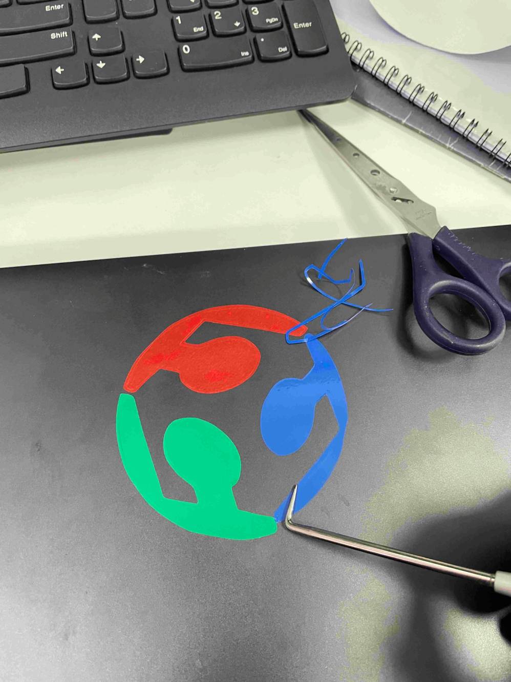
Weeding Process
After cutting, the extra vinyl surrounding the design was removed manually.
Steps:
- Lift unwanted vinyl using a weeding tool
- Slowly peel away the excess material
- Leave the final sticker attached to the backing sheet
Weeding process with additional correction tools like scissor
Final Result
The finished vinyl sticker was applied to my laptop.

Design Files
Download the original design files:
- Press-fit kit design (SVG)
- Vinyl cutter file (PLT)
Download Design Files
Zib format
[Fusion360 parametric design]https://skfb.ly/pIIG9
Final Project Progress
This week helped me understand how laser cutting precision and kerf compensation affect mechanical joints.
The parametric design approach will be useful later when developing components for my final project.