Week10
# Week10 Output Devices
SSTM
Group Assignment: — on progress
Individual Assignment:
- Add an output device to a self-designed microcontroller board, my PCB board ready and am on searching from different source for XIAO ESP 32 C3
- Program the device to perform a specific action … I did to align the Alarm system with my FP and Buzzer as output device.
1. Introduction to Output Devices
Output devices are components that receive signals from a microcontroller and convert them into physical actions such as light, sound, or movement.
2. Selected Output Devices
- LED → Visual alert
- Buzzer → Sound alarm
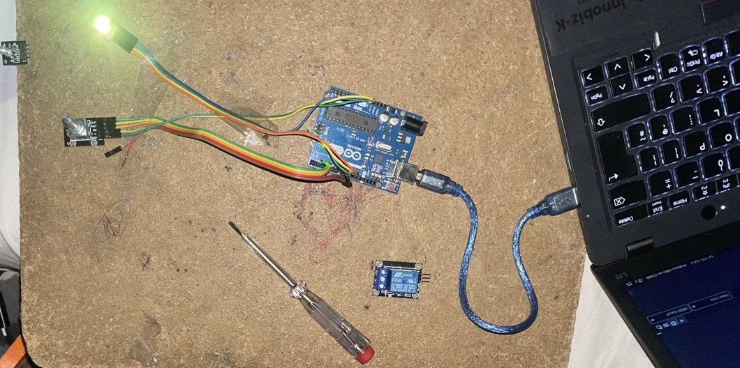
3. Circuit Connection
- LED → Pin 8
- Buzzer → Pin 9
- Both connected to GND
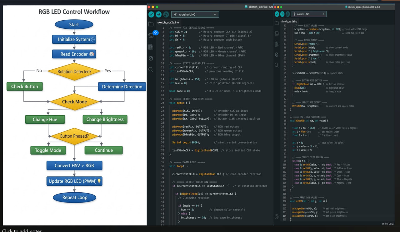
4. Arduino Code to learn the output devices with code integration
// ===== PIN DEFINITIONS =====
int CLK = 2;        // Rotary encoder CLK pin (signal A)
int DT = 3;         // Rotary encoder DT pin (signal B)
int SW = 4;         // Rotary encoder push button

int redPin = 9;     // RGB LED - Red channel (PWM)
int greenPin = 10;  // RGB LED - Green channel (PWM)
int bluePin = 11;   // RGB LED - Blue channel (PWM)

// ===== STATE VARIABLES =====
int currentStateCLK;    // current reading of CLK
int lastStateCLK;       // previous reading of CLK

int brightness = 150;   // LED brightness (0–255)
int hue = 0;            // color position (0–360 degrees)

bool mode = 0;          // 0 = color mode, 1 = brightness mode

// ===== SETUP FUNCTION =====
void setup() {

  pinMode(CLK, INPUT);        // encoder CLK as input
  pinMode(DT, INPUT);         // encoder DT as input
  pinMode(SW, INPUT_PULLUP);  // button with internal pull-up

  pinMode(redPin, OUTPUT);    // RGB red output
  pinMode(greenPin, OUTPUT);  // RGB green output
  pinMode(bluePin, OUTPUT);   // RGB blue output

  Serial.begin(9600);         // start serial communication

  lastStateCLK = digitalRead(CLK); // store initial CLK state
}

// ===== MAIN LOOP =====
void loop() {

  currentStateCLK = digitalRead(CLK); // read encoder rotation

  // ===== DETECT ROTATION =====
  if (currentStateCLK != lastStateCLK) {   // if rotation detected

    if (digitalRead(DT) != currentStateCLK) {
      // Clockwise rotation

      if (mode == 0) {
        hue += 5;          // change color smoothly
      } else {
        brightness += 10;  // increase brightness
      }

    } else {
      // Counterclockwise rotation

      if (mode == 0) {
        hue -= 5;          // reverse color direction
      } else {
        brightness -= 10;  // decrease brightness
      }
    }

    // ===== LIMIT VALUES =====
    brightness = constrain(brightness, 0, 255); // keep valid PWM range
    hue = (hue + 360) % 360;                    // keep hue in 0–359

    // ===== DEBUG OUTPUT =====
    Serial.print("Mode: ");
    Serial.print(mode);          // show current mode
    Serial.print(" | Brightness: ");
    Serial.print(brightness);    // show brightness value
    Serial.print(" | Hue: ");
    Serial.println(hue);         // show color position
  }

  lastStateCLK = currentStateCLK; // update state

  // ===== BUTTON MODE SWITCH =====
  if (digitalRead(SW) == LOW) {  // button pressed
    delay(200);                  // debounce delay
    mode = !mode;                // toggle mode
  }

  // ===== UPDATE RGB OUTPUT =====
  HSVtoRGB(hue, brightness);     // convert and apply color
}

// ===== HSV → RGB FUNCTION =====
void HSVtoRGB(int hue, int value) {

  float h = hue / 60.0;   // divide color wheel into 6 regions
  int i = floor(h);       // get region index
  float f = h - i;        // fractional part

  int p = 0;              // base value (no color)
  int q = value * (1 - f);
  int t = value * f;

  // ===== SELECT COLOR REGION =====
  switch(i % 6) {
    case 0: setRGB(value, t, p); break; // Red → Yellow
    case 1: setRGB(q, value, p); break; // Yellow → Green
    case 2: setRGB(p, value, t); break; // Green → Cyan
    case 3: setRGB(p, q, value); break; // Cyan → Blue
    case 4: setRGB(t, p, value); break; // Blue → Magenta
    case 5: setRGB(value, p, q); break; // Magenta → Red
  }
}

// ===== APPLY RGB VALUES =====
void setRGB(int r, int g, int b) {

  analogWrite(redPin, r);     // set red brightness
  analogWrite(greenPin, g);   // set green brightness
  analogWrite(bluePin, b);    // set blue brightness
}
Code source AI (with prompt “generate and write a code for RGB LED control with Rotary) **
5. How the Code Works and I learn
- The microcontroller continuously runs the
loop()function - It turns ON the LED and buzzer for 1 second
- Then turns them OFF for 1 second
- This repeats forever creating a blinking + beeping alert
7. Result
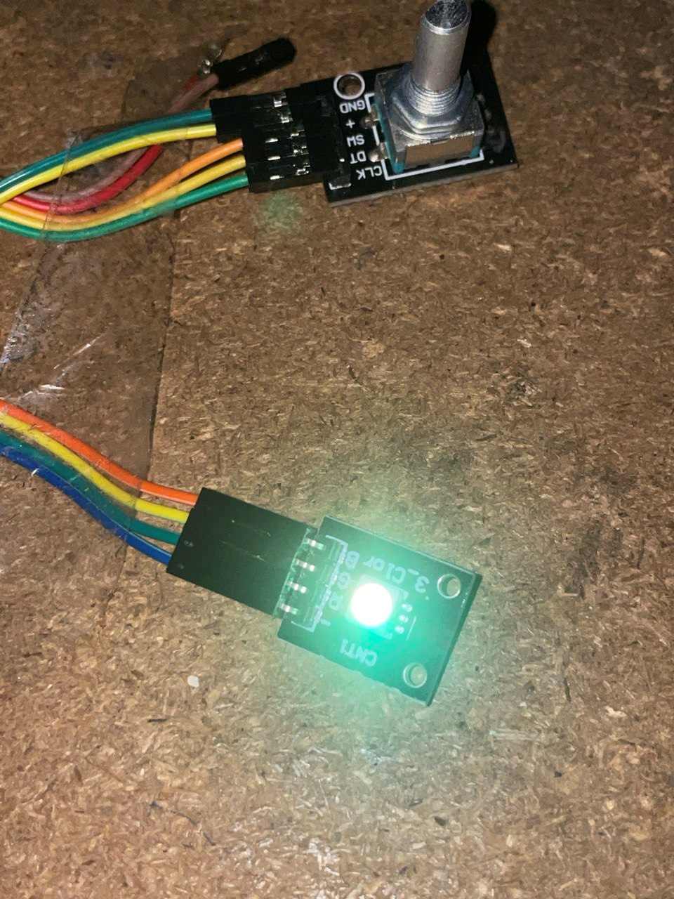
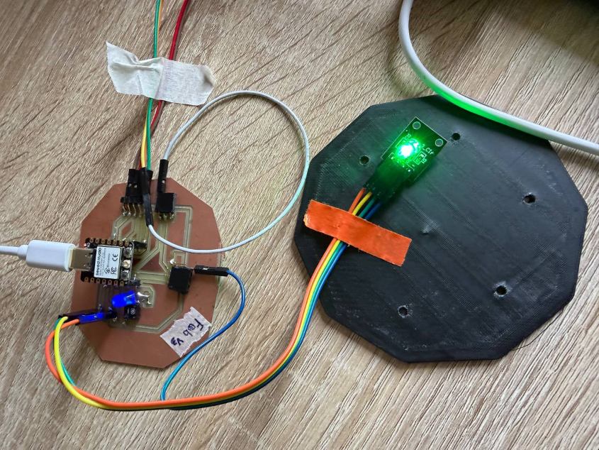
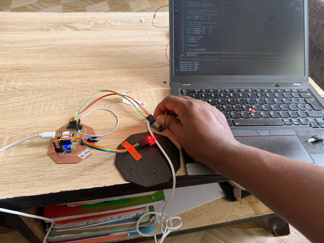
- LED blinks successfully
- Buzzer produces sound
- Outputs respond correctly to microcontroller signals
After I got my XIAO ESP32 C3 I did the following
Code from AI
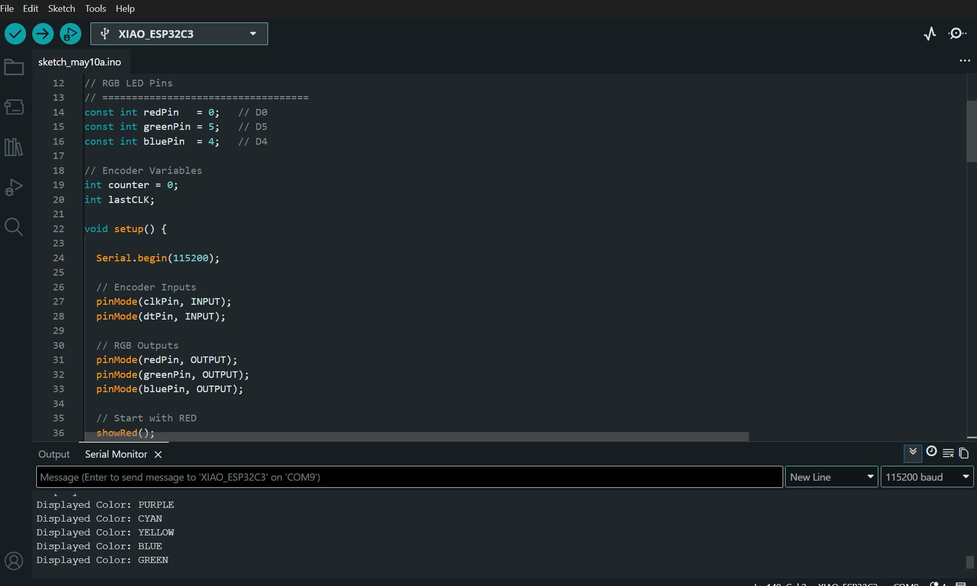
// XIAO ESP32-C3
// Rotary Encoder controls RGB LED
// Normal RGB LED (NOT IR)

// ===================================
// Rotary Encoder Pins
// ===================================
const int clkPin = 7;   // D7
const int dtPin  = 2;   // D2

// ===================================
// RGB LED Pins
// ===================================
const int redPin   = 0;   // D0
const int greenPin = 5;   // D5
const int bluePin  = 4;   // D4

// Encoder Variables
int counter = 0;
int lastCLK;

void setup() {

  Serial.begin(115200);

  // Encoder Inputs
  pinMode(clkPin, INPUT);
  pinMode(dtPin, INPUT);

  // RGB Outputs
  pinMode(redPin, OUTPUT);
  pinMode(greenPin, OUTPUT);
  pinMode(bluePin, OUTPUT);

  // Start with RED
  showRed();

  // Read initial CLK state
  lastCLK = digitalRead(clkPin);

  Serial.println("================================");
  Serial.println("RGB Encoder Control Started");
  Serial.println("Rotate Encoder");
  Serial.println("================================");
}

void loop() {

  int currentCLK = digitalRead(clkPin);

  // Detect encoder movement
  if (currentCLK != lastCLK && currentCLK == LOW) {

    // Clockwise
    if (digitalRead(dtPin) != currentCLK) {
      counter++;
    }

    // Counter Clockwise
    else {
      counter--;
    }

    // Keep value in range
    if (counter > 5) counter = 0;
    if (counter < 0) counter = 5;

    // ============================
    // Select Color
    // ============================

    switch(counter) {

      case 0:
        showRed();
        Serial.println("Displayed Color: RED");
        break;

      case 1:
        showGreen();
        Serial.println("Displayed Color: GREEN");
        break;

      case 2:
        showBlue();
        Serial.println("Displayed Color: BLUE");
        break;

      case 3:
        showYellow();
        Serial.println("Displayed Color: YELLOW");
        break;

      case 4:
        showCyan();
        Serial.println("Displayed Color: CYAN");
        break;

      case 5:
        showPurple();
        Serial.println("Displayed Color: PURPLE");
        break;
    }

    delay(2);
  }

  lastCLK = currentCLK;
}

// ===================================
// Color Functions
// ===================================

void showRed() {
  digitalWrite(redPin, HIGH);
  digitalWrite(greenPin, LOW);
  digitalWrite(bluePin, LOW);
}

void showGreen() {
  digitalWrite(redPin, LOW);
  digitalWrite(greenPin, HIGH);
  digitalWrite(bluePin, LOW);
}

void showBlue() {
  digitalWrite(redPin, LOW);
  digitalWrite(greenPin, LOW);
  digitalWrite(bluePin, HIGH);
}

void showYellow() {
  digitalWrite(redPin, HIGH);
  digitalWrite(greenPin, HIGH);
  digitalWrite(bluePin, LOW);
}

void showCyan() {
  digitalWrite(redPin, LOW);
  digitalWrite(greenPin, HIGH);
  digitalWrite(bluePin, HIGH);
}

void showPurple() {
  digitalWrite(redPin, HIGH);
  digitalWrite(greenPin, LOW);
  digitalWrite(bluePin, HIGH);
}
8. Conclusion
This assignment demonstrates how to:
- Control output devices
- Program microcontroller responses
- Build a simple RGB with rotary control system
