
Final Project

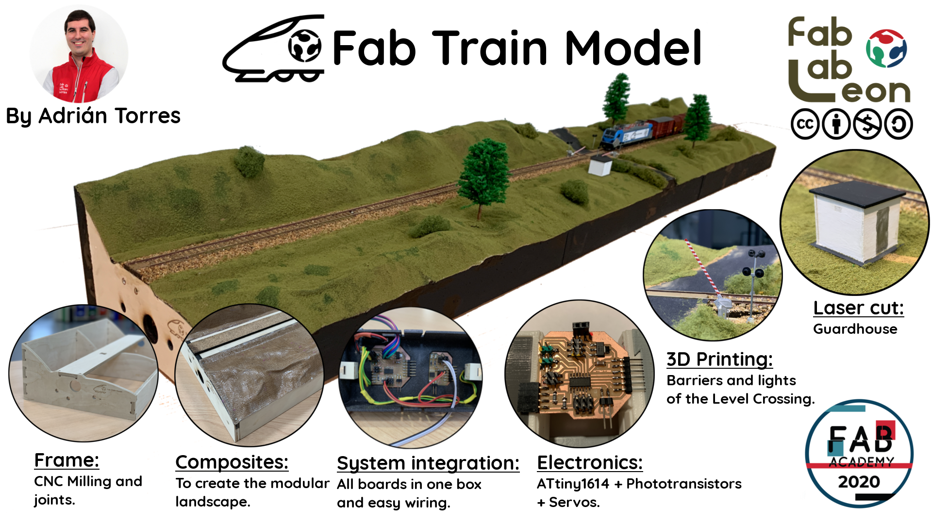
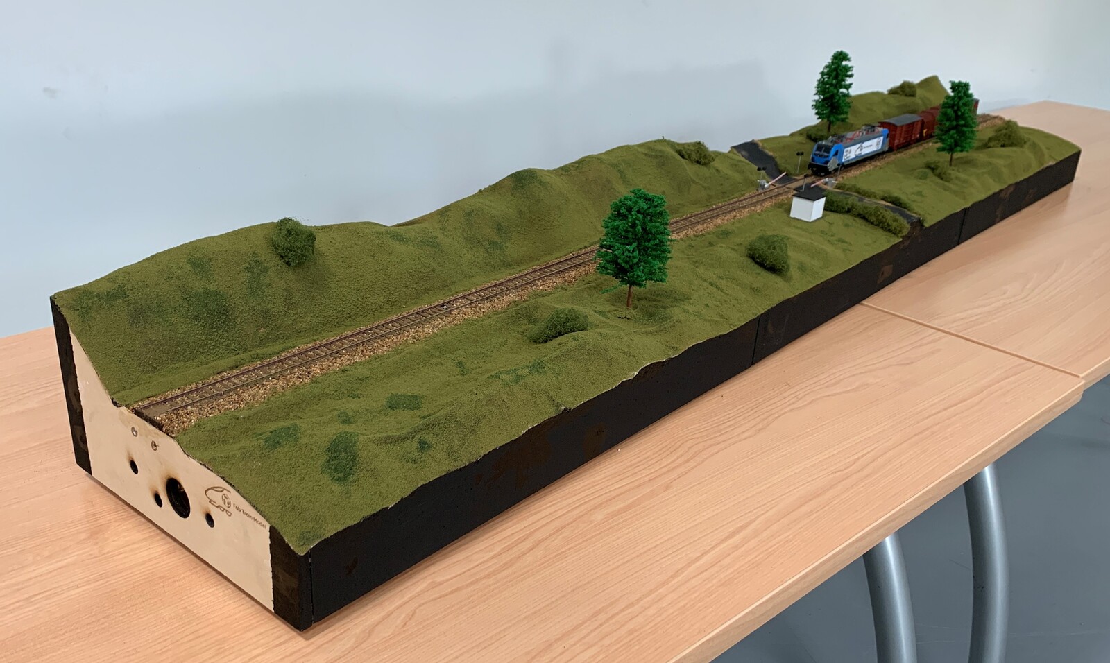
The Fab Train Model is a set of modules that are part of a model. It incorporates a train detection system that moves a level crossing. This detection system can be used for other options, such as changing the signals or moving the motors of the changes of a station.
I have milled the frame of the model with the CNC. For the electronics I use an ATtiny1614 with phototransistors to detect the train and servos to move the level crossing barriers. The barriers and signals are 3D printed. These boards are integrated into a 3D printed box. Below the track I have integrated the box with the electronics and cables. I modeled the landscape with Blender to later manufacture the composites. I put the track and decorate the landscape of the model.
Fab Train Model is compatible with other modules with the standars. Fab Train Model is a sturdy, lightweight model with multipurpose electronics. It incorporates very precise details thanks to digital fabrication.
This is the video of my presentation to the entire #fablabnetwork. I am very proud of the great reception of my project. Thank you very much. 😍
Answering:
What does it do?
The Fab Train Model is a set of modules that are part of a model. It incorporates a train detection system that moves a level crossing. Fab Train Model is compatible with other modules with the standars. Fab Train Model is a sturdy, lightweight model with multipurpose electronics. It incorporates very precise details thanks to digital fabrication.
Who's done what beforehand?
Actually at the Fab Academy there is no project on train model. I have been inspired by my association where we use the Maquetren regulations. With this regulation, the idea is to be able to build a model with standardized profiles to be able to connect with other colleagues and build a larger model.
You can find the Maquetren regulations here.
What did you design?
I have designed the frame, the composites, the level crossing barriers, the signs, the level crossing booth, the boards and even the small boards to hold the track.
What materials and components were used?
To create the landscape and the structure:
- Polystyrene.
- Bulap.
- Composite resin.
- 9 mm plywood.
For barriers and signals:
- PLA filament.
For decoration:
- Flexible track.
- Herbs for the landscape.
- Sandpaper for the road.
- White glue.
For electronics:
- 2 Phototransistors.
- 2 servos.
- 4 LEDs SMD 1608.
- 9V Power Supply or external power supply by Powerbank.
- 1 ATtiny1614.
- 1 ATtiny412.
- Several pin headers.
Where did they come from?
The landscape and structure materials came from local suppliers; the PLA filament from Prusament; the decoration from El Taller del Modelista and the electronic items from Digikey and Amazon.
How much did they cost?
Below is the complete list of all the materials to build your own Fab Train Model. Includes links in the description.
Fab Train Model |
Where to buy? | Amount | Price | Total price |
| Polystyrene. | Locally | 2 (1200 x 600 x 40 mm) | 3,00 €/unit | 6,00 € |
| Plywood 10 mm | Locally | 1 (1220 x 1220mm) | 20,00 €/unit | 20,00 € |
| Burlap | Locally | 1 (1500 x 700mm) | 10,00 €/unit | 10,00 € |
| Cork 5 mm | Locally | 1 (150 x 600mm) | 5,00 €/unit | 5,00 € |
| Epoxy Resin | Entropy Resins | 1 | 60,69 €/unit | 20,00 € |
| PLA 1,75mm. filament (3D Printing) | Prusament | 99 gr. | 23,74 €/kg. | 2,52 € |
| Battery 9V | Amazon | 1 | 3,75 € | 3,75 € |
| Battery clip | Amazon | 1 | 4,50 €/2 units | 2,25 € |
| Servo motor MG996R | Amazon | 2 | 3,98 €/unit | 7,96 € |
| Servos + Phototransistors PCB | Digikey | 1 | 3,00 €/unit | 3,00 € |
| LED´s Signs PCB | Digikey | 1 | 1,95 €/unit | 1,95 € |
| Proto Board FR1 | Digikey | 1 board | 1,24 €/unit | 1,24 € |
| Ground cover for landscape | Woodland Scenics | 2 | 11,50 €/unit | 23,00 € |
| Flexible Track, Wooden Sleeper | PECO | 3 | 4,95 €/unit | 14,85 € |
| Rail Joiner | PECO | 1 | 3,70 €/unit | 3,70 € |
| Others (wood glue, tape, soldering tin, DuPont cables…) | - | - | - | 5,00 € |
| Total cost/Fab Train Model | 130,22 € |
What parts and systems were made?
- Frame and the landscape.
- Barriers, signs, booth of the level crossing.
- Electronics.
What processes were used?
For the design of the level crossing barriers I have used FreeCAD and 3D printing. For the frame and landscape modeling I used Rhinoceros and Blender to shape it and I used the CNC and the composite technique. To design and manufacture the electronic boards I used Eagle and the milling and soldering process. For the programming of the microcontrollers I used Arduino and Linux. For the decoration I used paint, herbs ...
What questions were answered?
The incredible versatility of composites, the speed of its creation and its resistance. Also in the end I decided to use the phototransistors to detect the train instead of the time of flight due to its complexity when placing it under the track.
What worked? What didn't?
Initially, my idea was to use networking to communicate the phototransistors with the servo board, but programming was complicated for me (it is my weak point). So I decided to unify everything on a single board (inputs + outputs).
Creating the frame of the first prototype in wood with lag screws complicated the fit of the composites to the frame. The CNC is more precise than the manual construction mode hehe.
During the creation of the composites I relaxed in the manufacture of the last one and I made the mistake of not putting the film release and the blanket stuck to the composite. It is important in this process to keep the concentration of the process, because otherwise you will lose a full day of work.
Also some scare with the CNC as you will have seen in my documentation; but from mistakes you learn and it makes you be more aware and attentive to the machine.
How was it evaluated?
As I had commented in Applications and Implications, my project is made up of spiral development. Given the time that I had and that I present the first week because I have only managed to detect the train, the phototransistor lowers the level crossing barrier, turns on the lights and when the second phototransistor is detected, the barriers are raised and the lights are turned off. This only happens in one sense; As I mentioned, the ideal is that it should go in both directions.
At the frame level I have evolved a lot, because my main idea was to create the frame using traditional methods. When creating it with the CNC it is much more practical and precise, something incredible.
What are the implications?
Once the Fab Train Model is finished, my idea is to use it in the modular model exhibitions we do in Spain. I would like to continue investigating and be able to apply train detection for other uses such as managing a station for example.
I also think it would be useful to provide training within my company and to be able to explain different small-scale railway processes with models.
And surely I will write an article in the Maquetren magazine, explaining the wonderful process of creating this final project.
Fabrication Processes
For the layout of the mockup, use Blender to model the landscape and Rhinoceros to create the frame.
CNC. Frame + Composites
Using Rhinoceros, I design the model frame, following the Maquetren regulations so that it is compatible with the other modules to form a model.

Once the STL files extracted from Blender have been processed, and with Rhinoceros I prepare the molds that I am going to mill with the CNC in polystyrene. Using epoxy resin and burlap I create the composite where the landscape will go.

3D Printing
The barriers and the level crossing are the same as in reality, scaled to 1:87. You have more information in the week of Computer-Aided Design. As a complement I use styrene profiles to give more resistance to barriers or signs.

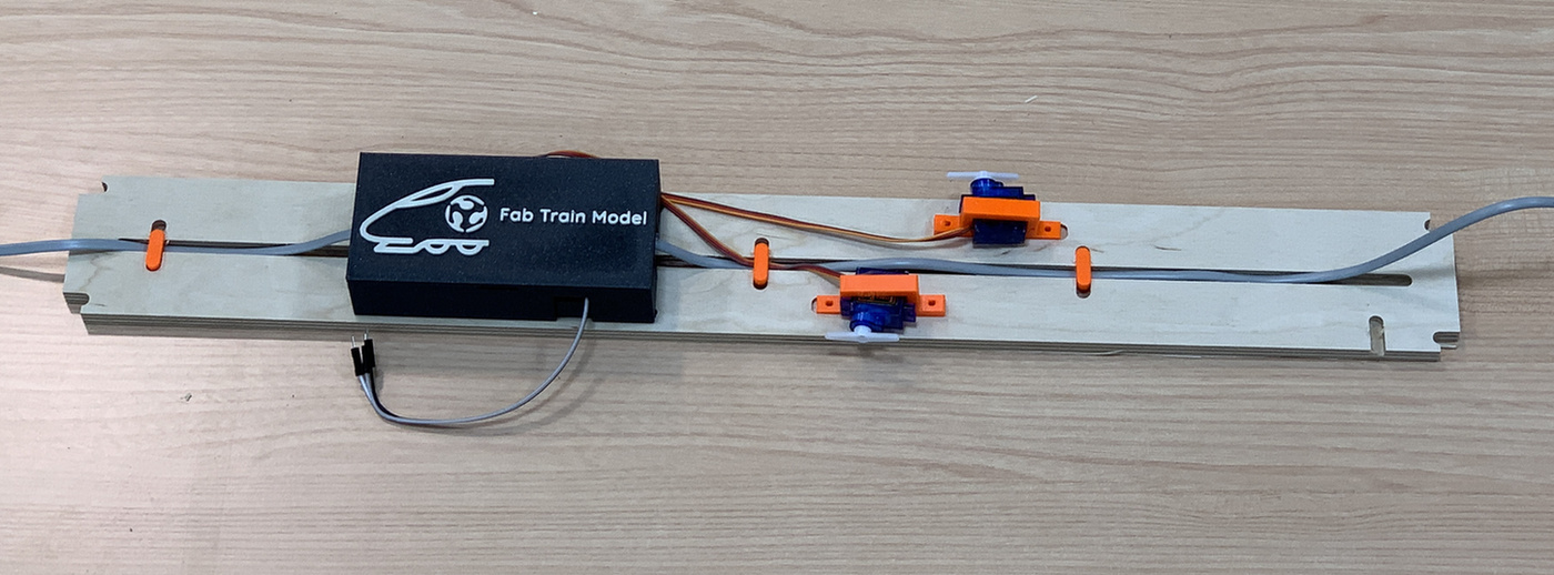
To integrate all the electronics, I design a box with the Fab Train Model logo; This box has tabs for easy removal and various holes to remove the connectors. To hold the servos or cables, I design different 3D printed supports.

Electronics Design and Production
During the week of Output Devices and Networking and Communications I made the boards that I was going to use in my project. The first is an ATtiny1614 that detects the two phototransistors and activates the servos. The second board is an ATtiny412 to control the level crossing lights.
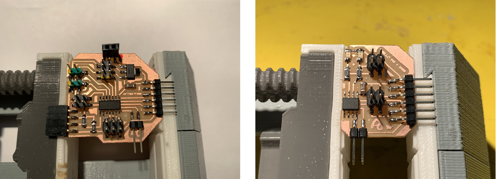
To place the track and align it I need a piece of board that can soldered the two rails. For this I create a PNG with Rhinoceros in the shape of the rails and the sleepers. The platform of the road where the phototransistor is located, has a 3D printed support where it houses a small board where the phototransistor is soldered with two connectors underneath to connect to the cable that goes to the system integration.

Please find below the completed BOM for these two PCBs:
Servos + Phototransistors PCB |
Where to buy? | Amount | Price | Total price |
| Proto Board FR1 | Digikey | 1/4 board | 1,24 €/unit | 0,31 € |
| ATtiny1614 | Digikey | 1 | 0,64 €/unit | 0,64 € |
| 1uF capacitor 50V | Digikey | 1 | 0,18 €/unit | 0,18 € |
| 4,99kΩ resistor | Digikey | 2 | 0,09 €/unit | 0,18 € |
| 10kΩ resistor | Digikey | 2 | 0,09 €/unit | 0,18 € |
| IR phototransistor | Digikey | 2 | 0,37 €/unit | 0,74 € |
| IC Regulator 5V 1A SOT223 | Digikey | 1 | 0,43 €/unit | 0,43 € |
| Pin header | Amazon | 34 | 0,01 €/unit | 0,34 € |
| Total cost Servos + Phototransistors PCB | 3,00 € |
LED´s Signs PCB |
Where to buy? | Amount | Price | Total price |
| Proto Board FR1 | Digikey | 1/4 board | 1,24 €/unit | 0,31 € |
| ATtiny412 | Digikey | 1 | 0,42 €/unit | 0,42 € |
| 1kΩ resistor | Digikey | 2 | 0,09 €/unit | 0,18 € |
| 1uF capacitor 50V | Digikey | 1 | 0,18 €/unit | 0,18 € |
| LED | Digikey | 2 | 0,35 €/unit | 0,70 € |
| Pin header | Amazon | 16 | 0,01 €/unit | 0,16 € |
| Total cost LED´s Signs PCB | 1,95 € |
Embedded Microcontroller Interfacing and Programming
The ATtiny1614 detects the train through the phototransistor, moves the servos and activates an output. When the train goes through the second phototransistor the output is turned off and I move the servos. I use an ATtiny412 to control the flickering of the level crossing lights through the activated output of the ATtiny1614.
//Adrián Torres. Fab Academy 2020
//ATtiny1614
//Fab Lab León

#include SoftwareSerial.h
#include Servo.h
Servo myservo1;  // create servo object to control a servo1
Servo myservo2;  // create servo object to control a servo2
int sensorPin1 = A0;    // analog input pin to hook the sensor to
int sensorPin2 = A1;    // analog input pin to hook the sensor to
int sensorValue1 = 0;  // variable to store the value coming from the sensor1
int sensorValue2 = 0;  // variable to store the value coming from the sensor2
int ledPin1 = 13;//first light
int posinicial = 60;    // initial position of the servos
int posfinal = 30;
int pos = posinicial;
int umbral = 100;  //minimum value of the sensor to activate the system

void setup() {
  Serial.begin(115200);
  myservo1.attach(3);  // attaches the servo on PA4 to the servo object
  myservo2.attach(6);  // attaches the servo on PA5 to the servo object
  pinMode(ledPin1, OUTPUT);
  myservo1.write(posinicial); //initial position of the servo
  myservo2.write(posinicial); //initial position of the servo
}


void loop() {

  sensorValue1 = analogRead(sensorPin1); // read the value from the sensor
  sensorValue1 = map(sensorValue1, 0, 1024, 1024, 0);
  sensorValue2 = analogRead(sensorPin2); // read the value from the sensor
  sensorValue2 = map(sensorValue2, 0, 1024, 1024, 0);

  //values in serial
  Serial.print("pos: ");
  Serial.print(pos);
  Serial.print("Valor 1:");
  Serial.print(sensorValue1);
  Serial.print("  ");
  Serial.print("Valor 2:");
  Serial.println(sensorValue2);
  //Serial.clear();


  if (sensorValue1 <= umbral) { //if the value is less than the threshold
   digitalWrite(ledPin1, HIGH);  //active the lights of the level crossing

   for (pos ; pos >= posfinal; pos -= 2) { //close the barrier
      myservo1.write(pos);
      myservo2.write(pos);
     delay(80);
    }

  }

     if (sensorValue2 <= umbral) { //if the value is less than the threshold
      digitalWrite(ledPin1, LOW);   //turn off the lights of the level crssing
      for (pos; pos <= posinicial; pos += 2) {   //open the barrier
      myservo1.write(pos);
      myservo2.write(pos);
      delay(80);
      }
    }

}
//Adrián Torres. Fab Academy 2020
//ATtiny412
//Fab Lab León
int ledPin1 = 0; //led1
int ledPin2 =1; //led2
void setup() {
pinMode(ledPin1, OUTPUT);
pinMode(ledPin2, OUTPUT);
}
void loop() {
digitalWrite(ledPin1, HIGH);
digitalWrite(ledPin2, LOW);
delay(750);
digitalWrite(ledPin1, LOW);
digitalWrite(ledPin2, HIGH);
delay(750);
}System Integration
This is the box with the two boards inside and with the cables and connectors distributed. With the RJ11 connectors it is easier to connect the two phototransistors found in the other two modules.
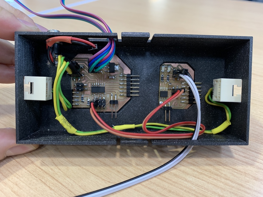
As the track platform underneath has recesses, it is possible to fit the electronics box and the servo supports. In addition, with a few small tabs you can fasten the cables. The platform containing the phototransistor has also milled the hole for the support and to fix the cables.

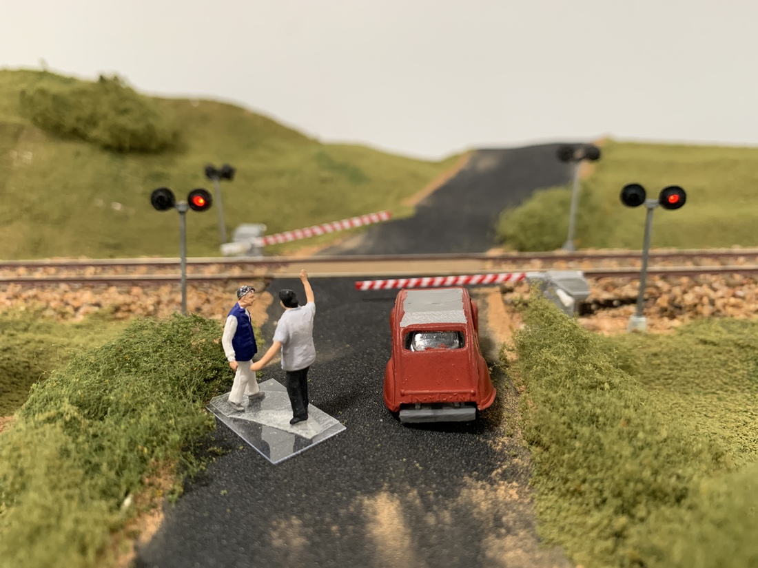
Decoration
Through different shades of grass, bushes, trees, the ballast for the rails and paint the model is ready.
As a detail for the presentation, put two small characters, Neil and me, who are talking about the project and the Fab Academy. 😅
Files
Here you will find all the files of the project. If you need more information about its construction, in Project Development you can find it. And if you need more information, you can contact me on the different Social Networks. 🤗