Final Project
Thanks.You.Mama.KATTY for.All
Final Project
Final Project
Final Project Video
Have you answered these questions?
- I.What does it do?✅
- II.Who's done what beforehand?✅
- III.What did you design?✅
- IV.What sources did you use?✅
- V.What materials and components were used?✅
- VI.Where did they come from?✅
- VII.How much did they cost?✅
- VIII.What parts and systems were made? ✅
- IX.What processes were used?✅
- X.What questions were answered? ✅
- XI.What worked? What didn't?✅
- XII.How was it evaluated? ✅
- XIII.What are the implications?✅
Answering the questions 📝❓
1. What does it do❓
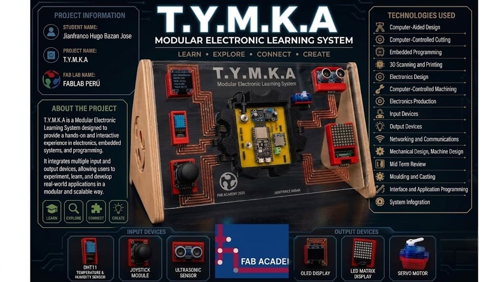
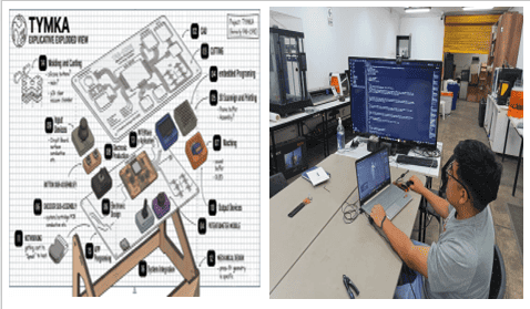
TYMKA (Thanks You Mamá Katty) is a modular educational platform designed to facilitate the learning of electronics , embedded programming, and digital fabrication through hands-on interaction.
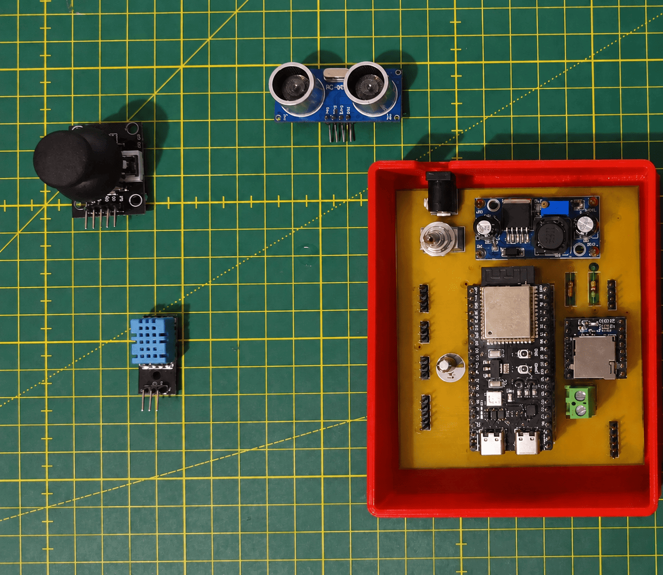
The system is based on an ESP32-S3 microcontroller and integrates multiple input and output modules connected through visible conductive copper tape pathways. Input devices include a joystick, an ultrasonic sensor, and a DHT11 temperature and humidity sensor. Output devices include an OLED display, an LED matrix, a servo motor, and an audio system based on a DFPlayer Mini and an 8Ω speaker.
TYMKA allows users to interact with sensors and actuators while visualizing how electronic signals flow through the system, reducing the complexity and clutter associated with traditional breadboard setups.
2. Who's done what beforehand❓📝
Several educational electronics platforms already exist, such as Arduino Starter Kits, BBC micro, and littleBits, which support project-based learning in electronics and programming.
A key inspiration for TYMKA was the work of Fab Academy graduate Ana Camila Luna Lopez, who developed a similar educational platform integrating digital fabrication and embedded systems.
TYMKA builds upon these ideas by integrating visible conductive pathways, modular components, and multiple digital fabrication processes into a single educational tool.
3. What did you design❓📝
I designed the mechanical, electronic, and software components required for the project.
This includes a custom ESP32-S3 PCB, the acrylic structure, CNC-machined supports, parametric slot joints developed in Rhinoceros and Grasshopper, and 3D-printed enclosures for the input and output modules.
I also developed the embedded firmware responsible for controlling the sensors, displays, audio system, and user interactions.
4. What sources did you use❓📝
The project was developed using official datasheets, technical documentation, online tutorials, and Fab Academy resources.
Key references include the ESP32-S3 documentation, component datasheets, Arduino libraries, and the Fab Academy archive. Additional sources include resources related to KiCad, Rhinoceros, Grasshopper, and Processing.
The project of Fab Academy graduate Ana Camila Luna Lopez served as a major reference and source of inspiration.
5. What materials and components were used❓📝
Materials and Components Used
The final project integrates mechanical, electronic, sensing, output, and software elements. The following table summarizes the materials and components according to their function within the system.
Structure & Fabrication
- Acrylic Sheets: Used for the external enclosure and structural support.
- Plywood Supports: Internal mounting structure for electronic modules.
- 3D Printed Parts (PLA): Custom housings, brackets, and mounting accessories.
- Conductive Copper Tape: Decorative and visible electrical routing.
- Screws, Spacers & Fasteners: Mechanical assembly and component fixation.
Power Management System
- Power Jack 5.5 × 2.1 mm: Main power input connector.
- ON-OFF-ON Toggle Switch: System power control.
- XL4005 DC-DC Step Down Module: Voltage regulation and power distribution.
- 100µF Capacitor: Voltage stabilization and filtering.
- SS34 Schottky Diode: Reverse polarity protection.
- 5.6kΩ Resistors: Signal conditioning and circuit protection.
- 2-Pin Terminal Block: External power connections.
Control Electronics
- ESP32-S3 Dev Kit C N16R8: Main microcontroller and system controller.
- Custom PCB: Designed specifically for system integration.
- Female Headers: Modular connection of sensors and output devices.
Input Devices
- Joystick Module: Manual navigation and user interaction.
- HC-SR04 Ultrasonic Sensor: Distance measurement and object detection.
- DHT11 Sensor: Temperature and humidity monitoring.
Output Devices
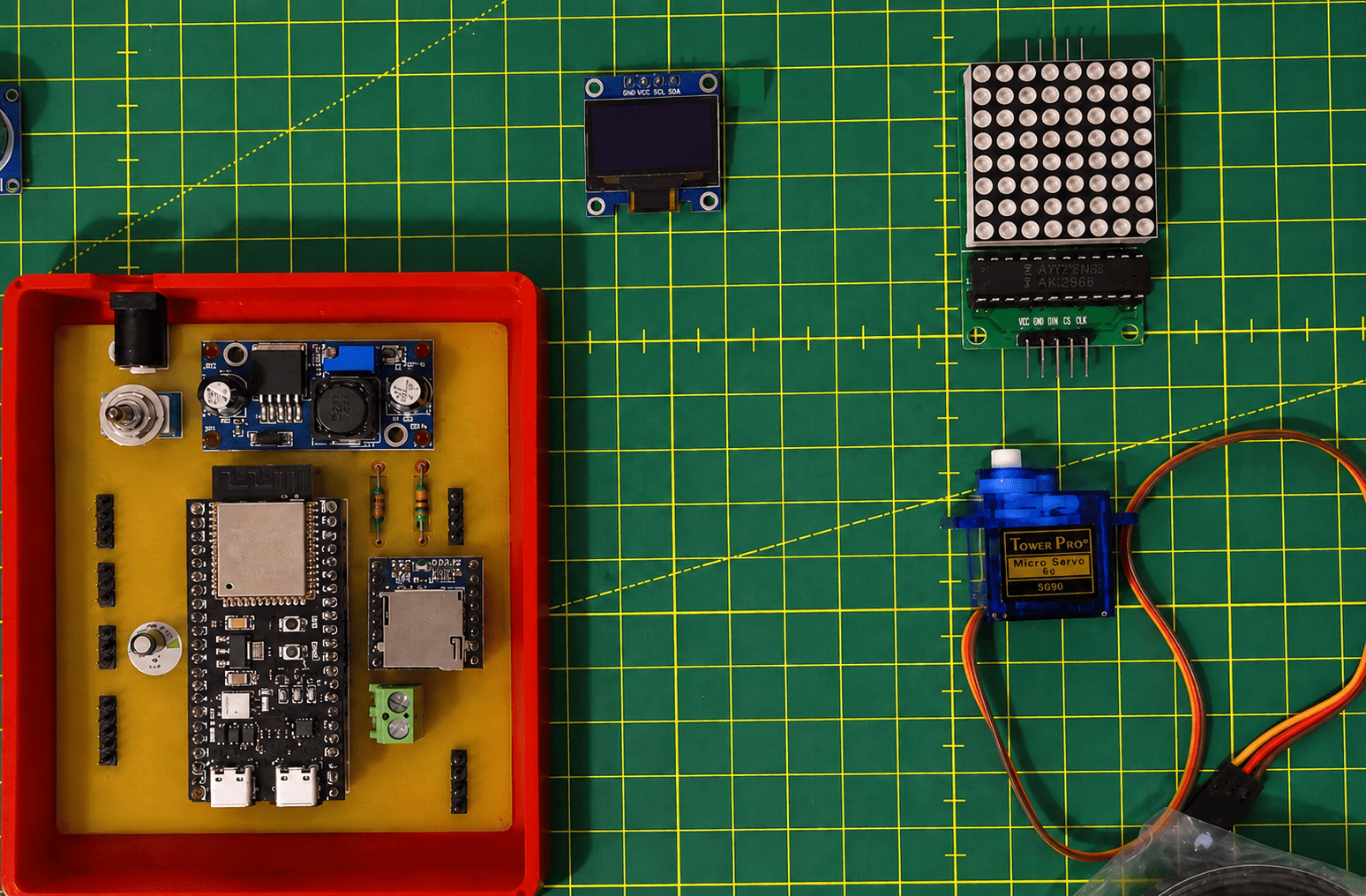
- 0.96" OLED Display (SSD1306): Visual feedback and system information.
- LED Matrix: Visual notifications and animations.
- SG90 Servo Motor: Mechanical actuation and movement.
- DFPlayer Mini MP3 Module: Audio playback system.
- 8Ω / 0.5W Speaker: Sound output and voice notifications.
Connections & Assembly
- Jumper Wires: Signal and power interconnections.
- Soldering Materials: PCB assembly and component integration.
- USB-C Cable: Programming and debugging connection.
Software & Development Tools
- KiCad: PCB design and schematic development.
- Rhinoceros 3D: Mechanical and enclosure design.
- Grasshopper: Parametric modeling and digital fabrication workflows.
- Arduino IDE: Firmware programming and testing.
- Processing: Data visualization and interface development.
6. Where did they come from?❓📝
Structure
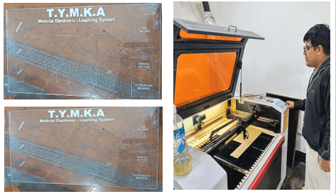
- Acrylic Sheets: Manufactured using laser cutting at FAB LAB UNI for the main structural and decorative components of the project.
- Plywood Supports: Fabricated using CNC machining at FAB LAB UNI to provide mechanical support and structural stability.
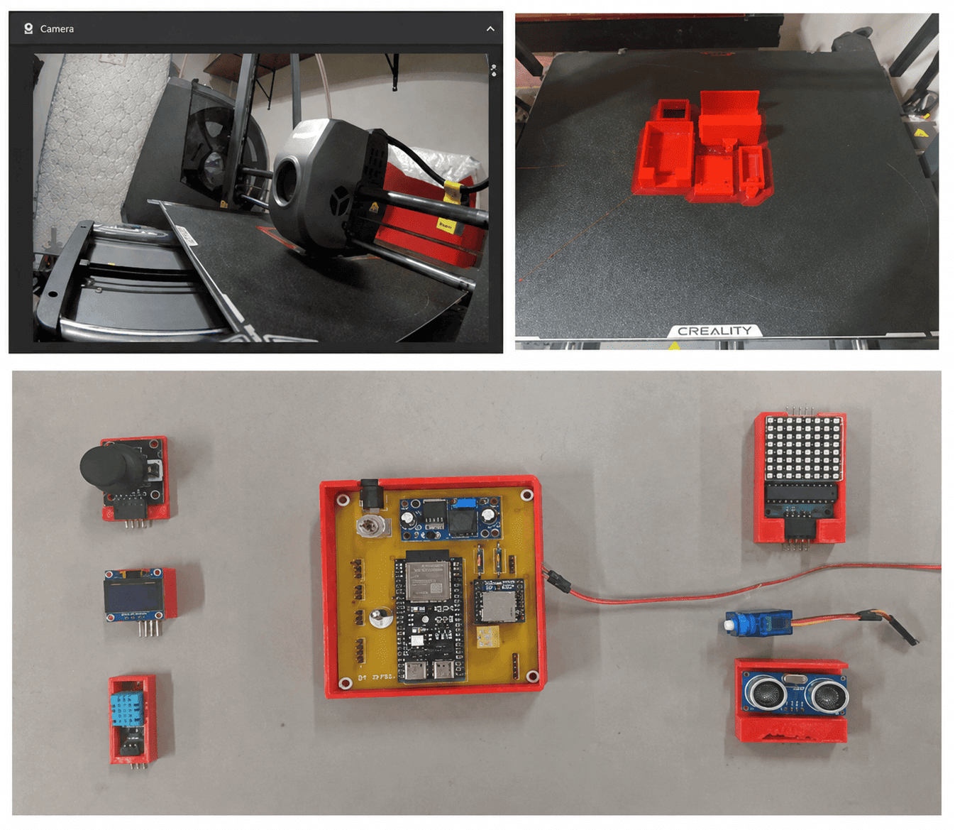
- 3D Printed Enclosures: Designed by me and manufactured using my own 3D printer for housing the input and output electronic modules.
- Assembly Hardware: Screws, spacers, nuts, and mounting accessories used for mechanical assembly and system integration.
Electronics
- Microcontroller: ESP32-S3 Dev Kit C N16R8 purchased from MTLAB Mechatronics Laboratory.
- Input Devices: Joystick Module, Ultrasonic Sensor, and DHT11 Temperature & Humidity Sensor acquired from MTLAB Mechatronics Laboratory.
- Output Devices: SSD1306 OLED Display, LED Matrix, SG90 Servo Motor, DFPlayer Mini Audio Module, and 8Ω Speaker purchased from MTLAB Mechatronics Laboratory.
- Power & PCB Components: Power Jack, ON/OFF Switch, LM2596 Voltage Regulator, Capacitors, Schottky Diode, Resistors, Female Headers, Terminal Blocks, and wiring sourced from MTLAB Mechatronics Laboratory.
Digital Fabrication & PCB Production
- Custom PCB: Designed in KiCad and fabricated using digital fabrication equipment available at FAB LAB UNI.
- Manufacturing Processes: PCB fabrication, laser cutting, CNC machining, and 3D printing were used to manufacture the different parts of the project.
- Software Tools: KiCad, Rhinoceros, Grasshopper, Arduino IDE, and Processing were used for electronic design, programming, modeling, and system development.
By combining commercially available electronic components from MTLAB Mechatronics Laboratory with locally fabricated parts produced at FABLAB UNI and on my personal 3D printer, the project remains affordable, reproducible, and compatible with standard Fab Lab digital fabrication workflows.
7. How much did they cost❓📝
here I use the tools of ChatGPT and the promp is "Give me a table where I can edit components,Quantity, price and Purpsoe"
💰 Materials Cost Table
The following table summarizes the main electronic and fabrication materials used in the development of the TYMKA project. Most electronic components were purchased from MTLAB Mechatronics Laboratory, while the structural parts were fabricated using digital fabrication processes at FAB LAB UNI and on my own 3D printer.
| 🧩 Component / Material | 🔢 Quantity | 💵 Unit Price (USD) | 🇵🇪 Unit Price (PEN) | 📝 Purpose |
|---|---|---|---|---|
| 🖥️ ESP32-S3 Dev Kit C N16R8 | 1 | $14.12 | S/ 49.00 | Main microcontroller responsible for processing, connectivity, and system control.Buy Here |
| 📺 OLED Display SSD1306 (0.96") | 1 | $5.19 | S/ 18.00 | Displays system status, sensor data, and user information.Buy Here |
| 🎵 DFPlayer Mini | 1 | $2.02 | S/ 7.00 | Audio playback module used for sound notifications and interaction.Buy Here |
| ⚙️ SG90 Servo Motor | 1 | $2.31 | S/ 8.00 | Provides mechanical movement for the system output mechanism.Buy Here |
| 🌡️ DHT11 Sensor | 1 | $2.31 | S/ 8.00 | Measures ambient temperature and humidity.Buy Here |
| 📏 HC-SR04 Ultrasonic Sensor | 1 | $2.31 | S/ S/ 8.00 | Detects distance and object presence.Buy Here |
| 🎮 Joystick Module | 1 | $0.84 | S/ 2.90 | Provides manual navigation and user input.Buy Here |
| 💡 LED Matrix | 1 | $1.73 | S/ 6.00 | Visual output device for icons, animations, and notifications.Buy Here |
| 🔊 Speaker 8Ω 0.5W | 1 | $1.01 | S/ 3.50 | Outputs audio generated by the DFPlayer Mini module.Buy Here |
| ⚡ LM2596 Buck Converter | 1 | $1.73 | S/ 6.00 | Regulates voltage supply for stable system operation.Buy Here |
| 🔌 Connectors, Headers & PCB Components | Various | $1.15 | S/ 4.00 | Includes resistors, capacitors, terminal blocks, switches, and connectors.Buy Here |
| 🟦 Acrylic Sheets | 1 | $1.44 | S/ 5.00 | Used to fabricate structural supports and enclosures through laser cutting.Buy Here |
| 🪵 Plywood / Triplay | 1 | $34.58 | S/ 120.00 | Provides mechanical support and structural rigidity.In front of the Universidad Nacional de Ingenieria |
| 🧵 PLA Filament | 1 | $15.85 | S/ 55.00 | Used to manufacture custom 3D-printed housings and mechanical parts.Buy Here |
| 🖨️ Custom PCB Fabrication | 1 | $20.17 | S/ 70.00 | Custom-designed PCB produced using digital fabrication processes.Buy Here |
| Total Project Cost | - | 💵 USD: $106.74 | 🇵🇪 PEN: S/ 370.40 | 📊 Final cost after component acquisition. |
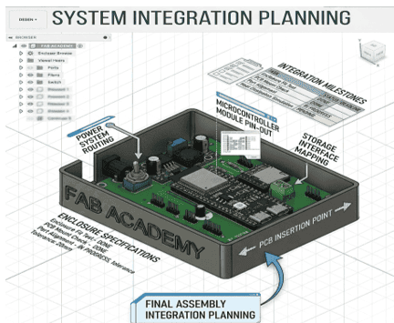
8. What parts and systems were made❓📝
Several custom parts and systems will be created for TYMKA. The physical components include a custom ESP32-S3 PCB, an acrylic structure, CNC-machined supports, parametric slot joints designed in Rhinoceros and Grasshopper, and 3D-printed enclosures for the input and output modules. Copper tape pathways will be used to create visible electrical connections between modules.
The electronic system integrates input devices (joystick, ultrasonic sensor, and DHT11) and output devices (OLED display, LED matrix, servo motor, and audio system). The software system consists of the embedded firmware running on the ESP32-S3, which controls all modules and manages user interaction.
Together, these elements form a modular educational platform for learning electronics, programming, and digital fabrication.
9. What processes were used❓📝
TYMKA incorporates a wide range of the digital fabrication and development processes learned throughout Fab Academy.
Computer-Aided Design (CAD) was used to create the project logo, the structural components, the Electronic Design, and the 3D models. Parametric design in Rhinoceros and Grasshopper was used to develop adjustable slot joints, allowing the structure to adapt to different material thicknesses by modifying a parameter.
Together, these elements form a modular educational platform for learning electronics, programming, and digital fabrication.
Computer-Controlled Cutting was used to manufacture the acrylic structure using laser cutting technology. Computer-Controlled Machining was applied to fabricate the support components using CNC equipment. 3D Printing was used to produce custom enclosures for the input and output modules.
Electronics Design was used to create a custom PCB based on the ESP32-S3 microcontroller, including power management and connections for multiple peripherals. PCB fabrication and assembly were carried out using digital fabrication tools and soldering processes.
Embedded Programming was used to develop the firmware that controls the sensors, displays, audio system, and actuators. Input Devices and Output Devices assignments are represented through the integration of sensors such as the joystick, ultrasonic sensor, and DHT11, as well as outputs including the OLED display, LED matrix, servo motor, and audio system.
Networking and Communications are implemented through the interaction between the ESP32-S3 and the connected modules.Interface and Application Programming may be incorporated through the future development of a Processing-based graphical interface.
System Integration is a fundamental part of the project, combining mechanical structures, electronics, programming, and user interaction into a single educational platform. In addition, concepts from Wildcard Week are explored by designing the PCB so that it can potentially be manufactured using alternative processes such as fiber laser cutting.
By integrating these processes into a single project, TYMKA demonstrates the application of many of the skills developed throughout the Fab Academy program.
10.What questions were answered❓📝
1. Will the conductive copper tape provide reliable electrical connections between all modules? The copper tape will be tested with all input and output devices to verify signal integrity, continuity, and long-term reliability. If necessary, connection points will be reinforced to improve electrical performance.
2. Can the custom ESP32-S3 PCB efficiently manage all connected devices? The PCB is designed to integrate power management, communication interfaces, and connections for multiple sensors and actuators. Testing will confirm stable operation when several modules are used simultaneously.
3. How can power be distributed safely throughout the system? A regulated power supply based on the LM2596 voltage regulator will be used to ensure stable voltage levels for all components while protecting the system from electrical issues.
4. Will the modular design improve the learning experience compared to traditional breadboard setups? The visible conductive pathways and modular organization are intended to help users better understand the relationship between electronic components, signals, and programming logic.
5. Is the parametric structure adaptable to different fabrication materials? The slot-based design developed in Rhinoceros and Grasshopper allows dimensions to be adjusted according to material thickness, improving flexibility and reproducibility.
6. Can the project successfully integrate multiple Fab Academy disciplines into a single platform? TYMKA combines CAD, electronics design, embedded programming, laser cutting, CNC machining, 3D printing, input devices, output devices, networking, interface programming, and system integration into one educational system.
7. Can the platform be easily replicated in other Fab Labs? The project uses standard digital fabrication processes, commercially available components, and open-source design tools, making replication possible in most Fab Lab environments.
11.What worked? What didn't❓📝
The custom PCB, embedded firmware, and modular structure operated successfully, integrating multiple input and output devices into a unified system.
The parametric design approach simplified fabrication and assembly.
One challenge was ensuring reliable electrical connections using conductive copper tape, which required testing and reinforcement at specific connection points.
Integrating multiple modules while maintaining a clean and intuitive user experience also required several design iterations.
11.1 Troubleshooting and Iterations
Several challenges were encountered during the development of TYMKA. One of the main issues involved the initialization of the MAX7219 LED matrix, which initially failed to display the snake game correctly. To identify the root cause, I verified the SPI connections, reviewed the library configuration, tested the matrix independently, and validated the power supply stability.
Another challenge was the transition from traditional jumper wires to conductive copper tape pathways. While the initial jumper-based prototype functioned correctly, it created visual clutter and reduced the educational value of the platform. Following the recommendations of my instructor, Roberto Delgado, the wiring system was redesigned using conductive copper tape.
Continuity and voltage tests were performed using a digital multimeter to ensure reliable electrical connections. This iterative process improved the aesthetics, usability, and clarity of the system while reinforcing the importance of modular debugging and user-centered design.
12.How was it evaluated❓📝
The project was evaluated based on functionality, integration, manufacturability, and educational value.
Success criteria included the correct operation of all input and output modules, reliable communication through the custom PCB, stable power distribution, adaptability of the parametric structure, and the effectiveness of the platform as a learning tool.
13. Engineering Evaluation and Testing Evidence
To validate the performance of TYMKA, functional tests were conducted on each subsystem individually before full system integration. The ultrasonic sensor, DHT11 sensor, OLED display, LED matrix, servo motor, and DFPlayer Mini were tested to verify correct operation, communication reliability, and stable power distribution.
Additional tests included real-time monitoring through the Arduino Serial Monitor, continuity verification of the conductive copper tape pathways using a digital multimeter, and voltage measurements across the power distribution system. The project was considered successful when all modules operated simultaneously without communication conflicts or power instability.
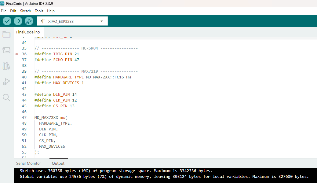
13.1 Firmware Validation and Resource Usage
The embedded firmware for TYMKA was developed and tested using Arduino IDE 2.3.9. The code integrates multiple libraries and communication protocols to control all input and output devices connected to the ESP32-S3.
This validation process ensured reliable integration of the OLED display, DHT11 sensor, ultrasonic sensor, MAX7219 LED matrix, servo motor, and other peripherals into a single embedded application.
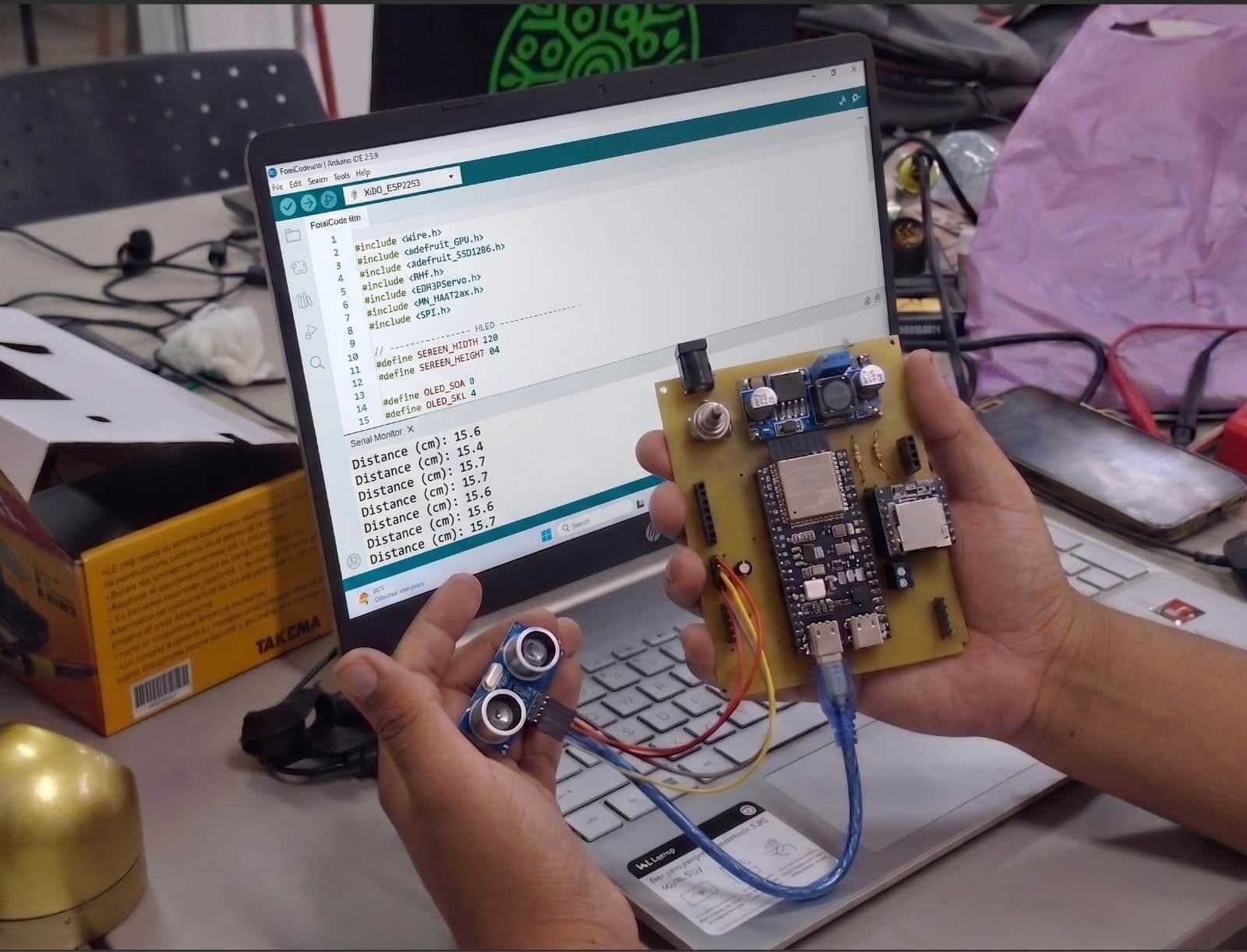
13.2 Ultrasonic Sensor Validation Test
This test was conducted to validate the integration between the custom PCB, the ESP32-S3 Dev Kit, and the HC-SR04 ultrasonic sensor. The sensor was connected to the system and the measured distance values were monitored in real time using the Arduino IDE Serial Monitor.
Multiple measurements were recorded to verify sensor stability, communication reliability, and data consistency. The results showed repeatable distance readings with minimal variation, confirming the correct operation of the sensor and its successful integration into TYMKA
This testing phase also helped verify the correct pin configuration, power distribution, and firmware implementation before integrating the sensor into the final educational platform.
13.3 Servo Motor Functional Test
This test was conducted to validate the control and integration of the SG90 servo motor with the custom TYMKA PCB and the ESP32-S3 microcontroller. The servo motor was connected to the platform and controlled through embedded firmware developed in Arduino IDE.
During the testing phase, different angular positions were programmed and verified to ensure accurate movement, stable power delivery, and reliable signal transmission. The Serial Monitor was used to confirm the correct execution of the control commands and to identify potential issues during system integration.
The successful operation of the servo motor demonstrated the ability of TYMKA to control actuators in real time, providing users with a practical understanding of motion control and output devices within embedded systems.
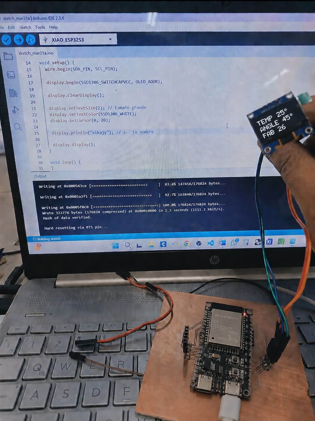
13.4 Early Functional Prototype and View in OLED
This image shows one of the first functional prototypes developed for TYMKA. The prototype integrated an ESP32-S3 development board, an OLED display, a servo motor, and a temperature sensor to validate the interaction between input data, embedded processing, and output devices.
The OLED display was programmed to show the servo motor angle, ambient temperature readings, and personalized system information, while the servo motor responded to programmed position changes in real time. This initial implementation allowed me to verify communication protocols, test library compatibility, and evaluate the performance of the ESP32-S3 before integrating additional modules into the final system.
Developing this early prototype was essential for identifying hardware and software requirements, validating the core functionalities of the platform, and guiding subsequent design decisions for the custom PCB and modular architecture of TYMKA.
14.What are the implications❓📝
TYMKA demonstrates how digital fabrication and embedded systems can be combined to create accessible educational tools.
The project reduces the complexity of learning electronics by replacing traditional breadboard wiring with visible conductive pathways.
Its modular and replicable design allows adaptation to different educational contexts and Fab Labs, encouraging hands-on learning and promoting wider access to electronics and digital fabrication education.
Assignments Applied in TYMKA
The Principles and Practices and Project Management week established the foundation for the development of TYMKA. During this stage, I defined the main objective of the project: to create a modular educational platform that simplifies the learning of electronics, embedded programming, and digital fabrication through hands-on interaction.
This assignment helped me identify the needs of potential users, define the project scope, and establish the core functionalities of the system. I determined that TYMKA would integrate multiple input and output devices using an ESP32-S3 microcontroller, while minimizing the use of traditional jumper wires through visible conductive copper tape connections.
Throughout the program, the project evolved iteratively as new skills and fabrication processes were incorporated. Each assignment contributed directly to the final outcome, including computer-aided design, electronics design, embedded programming, computer-controlled cutting, 3D printing, networking, and system integration.
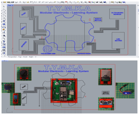
The Computer-Aided Design (CAD) assignment played a fundamental role in the development of TYMKA by enabling the design and visualization of all mechanical and graphical components before fabrication. During this stage, I created the project logo, developed the overall structure of the platform, and designed the layout of the input and output modules to ensure an intuitive learning experience.
During this assignment, I designed the project logo and developed the overall structure of the educational platform using digital modeling tools. Rhinoceros and Grasshopper were used to create a parametric design for the support system, allowing the slot joints to be adjusted according to different material thicknesses. This approach increased the flexibility and adaptability of the design, making it easier to manufacture the structure using various acrylic or plywood thicknesses.
Using Rhinoceros and Grasshopper, I developed a parametric support system with adjustable slot joints that can be adapted to different material thicknesses. This approach increased the flexibility and manufacturability of the project, allowing the structure to be fabricated using various acrylic or plywood thicknesses.
CAD tools also enabled the creation of 3D models for the module enclosures and helped identify potential design issues early in the process, reducing material waste and ensuring compatibility between subsequent fabrication processes such as laser cutting, CNC machining, 3D printing, and system integration.
The Electronic Design assignment was essential for transforming the concept of TYMKA into a functional and integrated educational platform. During this stage, I designed a custom PCB based on the ESP32-S3 Dev Kit C N16R8, integrating the power management system, communication interfaces, and connection points for multiple input and output modules.
Using KiCad, I developed the schematic and PCB layout, incorporating components such as the LM2596 voltage regulator, DFPlayer Mini, resistors, capacitors, Schottky diode, connectors, and female headers. The design was optimized to reduce the use of traditional jumper wires and facilitate the connection of modules through visible conductive copper tape pathways.
This assignment allowed me to understand the complete electronics design workflow, from component selection and circuit validation to PCB routing and preparation for fabrication. The resulting board became the core of TYMKA, enabling the integration of sensors, actuators, and communication systems into a single, compact, and educational device.
The
The Computer-Controlled Cutting assignment played a key role in the fabrication of TYMKA by enabling the precise manufacturing of the acrylic structure that supports the entire educational platform. During this stage, I used laser cutting technology to produce the main structural components, ensuring accuracy, repeatability, and efficient material usage.
Using Rhinoceros and Grasshopper, I developed a parametric slot-joint system that allows the structure to adapt to different material thicknesses by simply modifying design parameters. This flexibility makes the project easier to replicate and customize according to the available materials and fabrication requirements.
This assignment contributed significantly to the modularity and assembly of TYMKA, providing a clean and organized layout for the input and output modules while reducing assembly complexity. The resulting structure facilitated system integration and enhanced the overall user experience of the platform.
The 3D Printing assignment contributed significantly to the development of TYMKA by enabling the creation of custom enclosures for the input and output modules. These enclosures were designed to securely house components such as the joystick, ultrasonic sensor, DHT11 sensor, OLED display, LED matrix, and servo motor, improving the organization and usability of the platform.
Using CAD software in this case Was Fusion360 , I designed the enclosures to ensure proper integration with the acrylic structure and the conductive copper tape connections. The parts were optimized for additive manufacturing, considering factors such as print orientation, material usage, assembly, and ease of maintenance.
All components were fabricated using my own 3D printer with PLA filament, allowing rapid prototyping and iterative design improvements. This assignment enhanced the modularity, aesthetics, and functionality of TYMKA while demonstrating how additive manufacturing can be used to create customized educational tools.
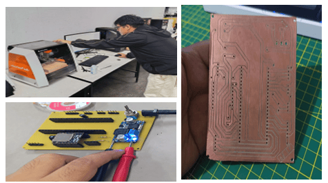
The Electronics Production assignment was essential for transforming the electronic design of TYMKA into a physical and functional device. During this stage, I fabricated the custom PCB designed in KiCad, which serves as the central control unit of the platform and integrates the ESP32-S3 Dev Kit C N16R8, power management components, and connection points for the input and output modules.
The PCB was manufactured at FABLAB UNI using the CNC milling process, which allowed precise and efficient fabrication directly from the digital design files. After milling, I performed the soldering and assembly of all surface-mount and through-hole components, including the LM2596 voltage regulator, DFPlayer Mini, capacitors, resistors, Schottky diode, connectors, and female headers.
This assignment provided hands-on experience in the complete electronics production workflow, from preparing manufacturing files and operating CNC equipment to assembling and testing the board. The resulting PCB became the core of TYMKA, enabling reliable integration of sensors, actuators, and communication systems within a compact and modular educational platform.
A6.1 PCB Manufacturing Process-Schematic Design
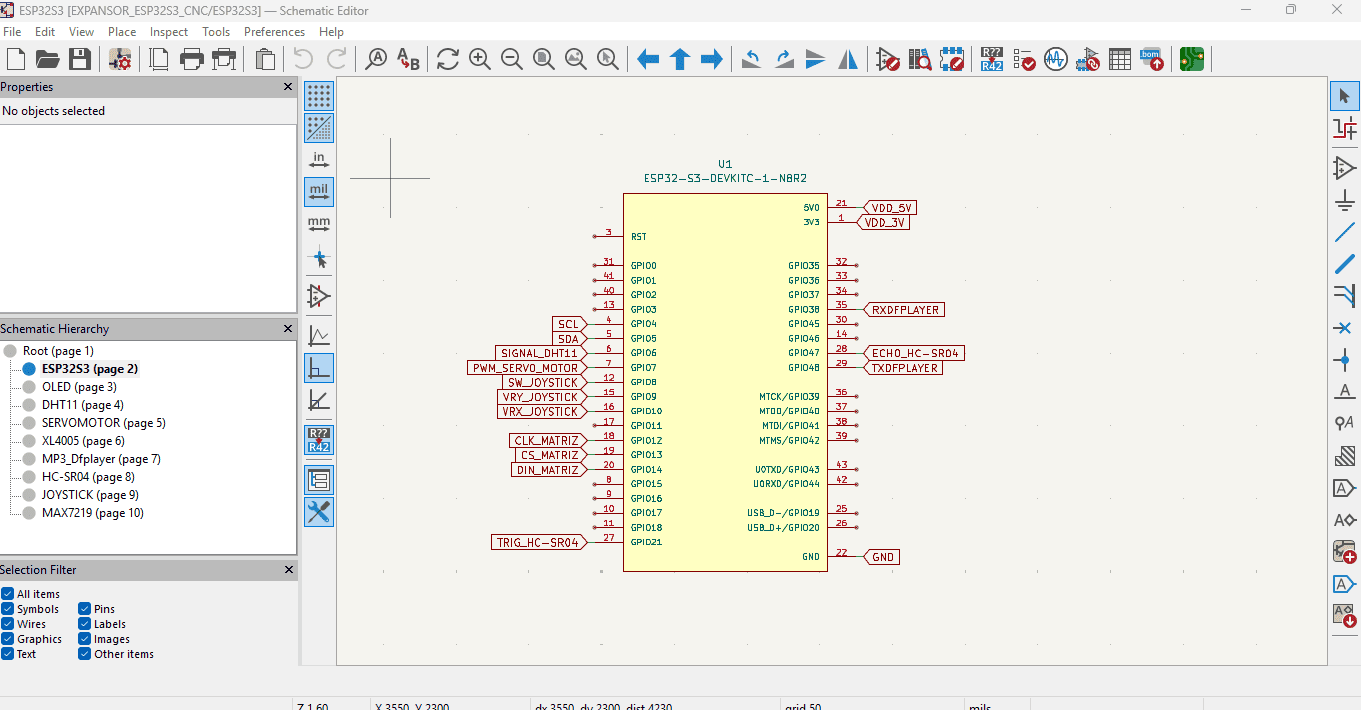
The schematic design phase was the starting point for the development of TYMKA's custom PCB. Using KiCad, I created the electronic schematic to define the relationships, connections, and communication interfaces between the ESP32-S3 Dev Kit C N16R8 and all the input and output modules integrated into the platform.
The schematic includes the power management system based on an LM2596 DC-DC step-down converter, protection components such as a Schottky diode, filtering capacitors, connectors, and female headers for the ESP32-S3. It also incorporates dedicated connections for the OLED display, joystick module, DHT11 sensor, ultrasonic sensor, MAX7219 LED matrix, SG90 servo motor, DFPlayer Mini audio module, and speaker.
Special attention was given to pin assignment, communication protocols, and power distribution to ensure compatibility and reliable operation. The design integrates multiple interfaces, including I2C for the OLED display, SPI for the LED matrix, UART for the DFPlayer Mini, and digital and analog inputs for the remaining modules.
Developing the schematic allowed me to validate the overall system architecture before fabrication, identify potential design conflicts, and optimize the integration of all components into a single modular educational platform.
A6.2 ESP32-S3 Microcontroller Integration for TYMKA
The core of the system architecture centers on the ESP32-S3-DEVKITC-1-N8R2, a powerful and versatile microcontroller chosen for its robust processing capabilities and extensive I/O options required for modular electronic learning. In the schematic design, the ESP32-S3 is configured to act as the primary interface hub, facilitating communication with a diverse range of peripherals including an OLED display, a DHT11 environmental sensor, and an HC-SR04 ultrasonic sensor. To ensure seamless interaction, specific GPIO pins have been mapped to handle distinct functions: servo motor control via PWM, joystick inputs for user interaction, and serial communication pathways dedicated to the MP3 DFPlayer and MAX7219 LED matrix drivers.
This hardware implementation is meticulously organized into a hierarchical structure within the KiCad schematic editor to maintain modularity and ease of troubleshooting throughout the development cycle. By segregating individual subsystems—such as power management (XL4005), audio playback, and sensor data acquisition—onto dedicated pages
Special attention was given to pin assignment, communication protocols, and power distribution to ensure compatibility and reliable operation. The design integrates multiple interfaces, including I2C for the OLED display, SPI for the LED matrix, UART for the DFPlayer Mini, and digital and analog inputs for the remaining modules.
Developing the schematic allowed me to validate the overall system architecture before fabrication, identify potential design conflicts, and optimize the integration of all components into a single modular educational platform.
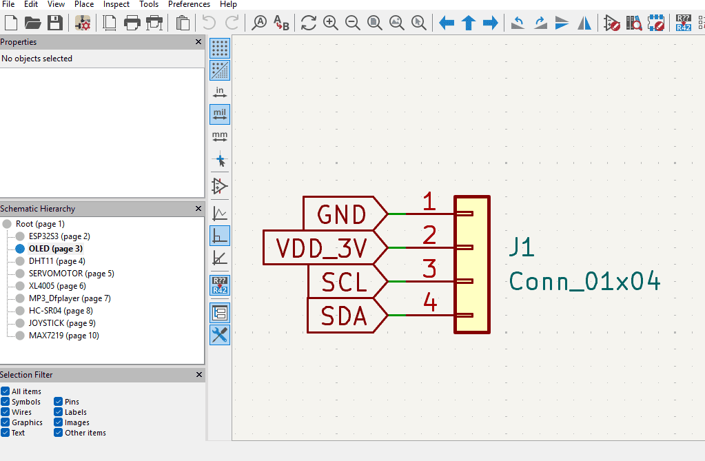
A6.3 OLED DISPLAY for TYMKA
The OLED display module is integrated into the system using a standard 4-pin 0.1" header (J1), facilitating a clean and reliable connection via the I2C (Inter-Integrated Circuit) communication protocol. This interface requires only four connections: ground (GND), 3.3V power (VDD_3V), and the two data lines, Serial Clock (SCL) and Serial Data (SDA). By utilizing this synchronous serial bus, the ESP32-S3 can efficiently transmit graphical data and text information to the display while minimizing the total number of GPIO pins consumed, which is essential for maintaining the modularity and expansion capabilities of the TYMKA system.
This design choice ensures both electrical compatibility and mechanical simplicity, allowing for quick deployment or replacement of the display module during the testing and assembly phases of the project. ensuring that signal integrity is maintained from the microcontroller's I2C pins to the display's input. This structured implementation highlights the project's adherence to modular electronics standards, providing a clear reference for the communication pathway that will drive the user interface feedback during the learning activities.
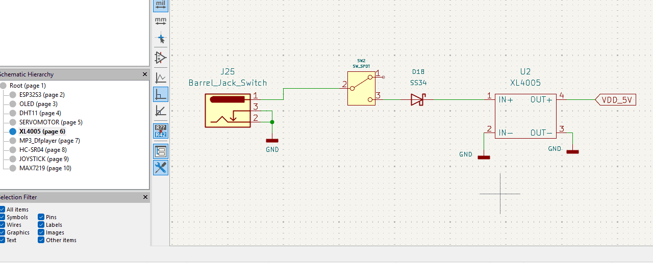
A6.4 Power Management and Regulation Stage for TYMKA
The power supply subsystem for the TYMKA project is designed to provide stable, reliable power to the main controller and peripherals. The input stage utilizes a barrel jack connector (J25) paired with a SPDT switch, allowing for physical power control and secure connection to an external DC power source. Following the input, an SS34 Schottky diode is strategically placed in series to provide reverse polarity protection, safeguarding the sensitive electronic components from potential damage due to accidental misconnection.
Central to this module is the XL4005 DC-DC step-down buck converter (U2), which efficiently regulates the incoming voltage to a steady 5V (VDD_5V). This switching regulator is chosen for its high efficiency and current-handling capabilities, essential for powering the ESP32-S3 and the various active sensors and modules within the system. By isolating the power regulation circuit into this dedicated module, the design ensures clean power distribution
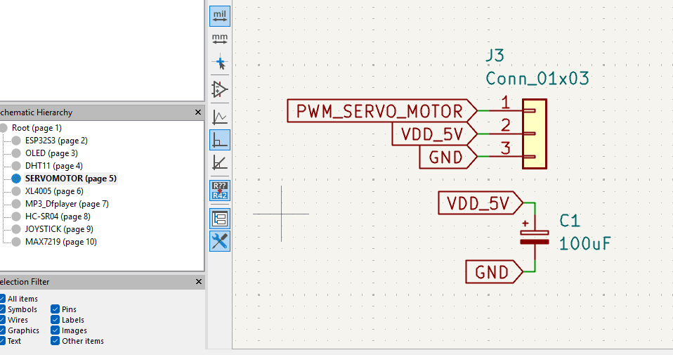
A6.5 Servomotor Control
The servomotor control module is designed to provide precise actuation for the TYMKA system while ensuring electrical stability. The connection interface uses a standard 3-pin 0.1" header (J3) to route the Pulse Width Modulation (PWM) signal from the ESP32-S3, along with 5V power (VDD_5V) and ground (GND). This interface configuration allows for quick, modular attachment of various hobbyist servomotors, which is critical for prototyping and adapting the system's mechanical movements during educational activities.
To maintain signal integrity and mitigate the electrical noise often generated by inductive loads like servomotors, a 100uF decoupling capacitor (C1) is placed in parallel across the power supply lines. This capacitor acts as a local energy reservoir, smoothing out transient voltage spikes and ensuring a stable power delivery during the motor’s operation. This implementation reflects best practices in PCB design, protecting the sensitive microcontroller from back-EMF and power instability
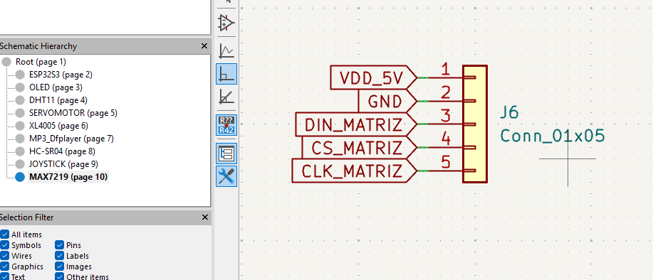
A6.6 LED Matrix
The LED matrix display module is integrated into the TYMKA system using a 5-pin 0.1" header (J6), which provides the necessary power and digital control lines to drive the MAX7219 driver IC. This interface manages the power supply (VDD_5V and GND) and the three-wire Serial Peripheral Interface (SPI) communication lines: Data In (DIN), Chip Select (CS), and Clock (CLK). By utilizing this synchronous serial protocol, the ESP32-S3 can efficiently transmit bitmapped data to the LED matrix, enabling dynamic visual outputs such as scrolling text, icons, or graphical animations that serve as key interactive elements for the learning platform.
This modular connection strategy is essential for the system’s design, as it allows for the potential daisy-chaining of multiple LED matrices to expand the visual display area without requiring additional GPIO pins from the primary microcontroller. The clean separation of the SPI signals within the schematic ensures high-speed, reliable data transmission, which is critical for preventing visual artifacts and flickering during graphical updates.
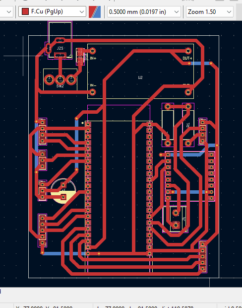
A6.7 PCB Layout Design and Routing Strategy
The printed circuit board (PCB) for the TYMKA project has been engineered with a focus on signal integrity, power efficiency, and compact form factor. The layout utilizes a primary top-layer copper pour (indicated in red) for the majority of the signal and power traces, ensuring low-resistance paths for the main current loops, particularly from the power input stage through the XL4005 buck converter. Strategic placement of components—such as the central ESP32-S3 module and its surrounding headers—minimizes trace length to reduce parasitic inductance and crosstalk, which is essential for stable operation of high-speed digital communications like SPI and I2C.
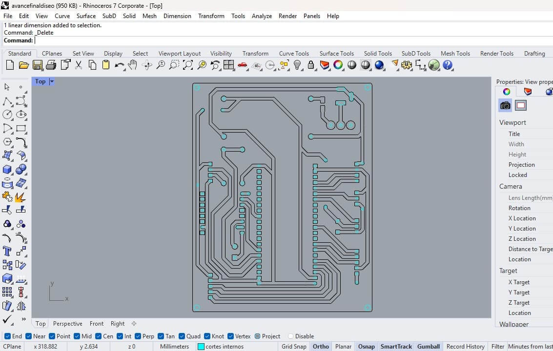
A6.8 PCB Vectorization for CNC Milling
Once the PCB layout was completed, the next step was to prepare the design for fabrication using the Roland SRM-20 CNC milling machine. The PCB files were imported into Rhinoceros (Rhino) to generate a clear and organized vector representation of the conductive traces, pads, and drilling locations.
Different colors were assigned to distinguish each machining operation. The black lines represent the engraving paths that define the conductive traces and isolate the copper areas on the board. The light blue circles indicate the drilling positions for through-holes and component soldering points.
This color-coded approach simplified the preparation of the manufacturing files and reduced the risk of errors during the CNC setup process. By separating the engraving and drilling operations, it was possible to optimize machining parameters such as tool diameter, cutting depth, and feed rate for each task.
The final vectorized design served as the basis for generating the toolpaths used by the Roland SRM-20, enabling the accurate fabrication of the custom TYMKA PCB and ensuring proper alignment between the conductive traces and the soldering holes.
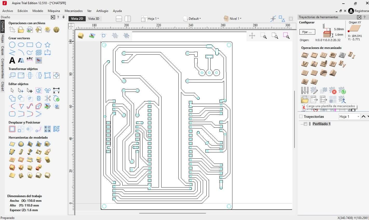
A6.9 Toolpath Generation and CNC Configuration
After completing the PCB vectorization process in Rhinoceros, the design was exported as a DXF file and imported into Aspire to prepare it for fabrication with the Roland SRM-20 CNC milling machine.
Within Aspire, the machining operations were configured by assigning different toolpaths according to the function of each vector. The vectors corresponding to the conductive traces were selected for the engraving operation, which removes the surrounding copper to create the electrical pathways. The vectors representing the component holes were configured as internal cutting operations to ensure accurate drilling positions for soldering and assembly.
Specific machining parameters, including tool diameter, cutting depth, spindle speed, and feed rate, were defined for each operation to achieve precise results and prevent damage to the copper-clad bakelite board.
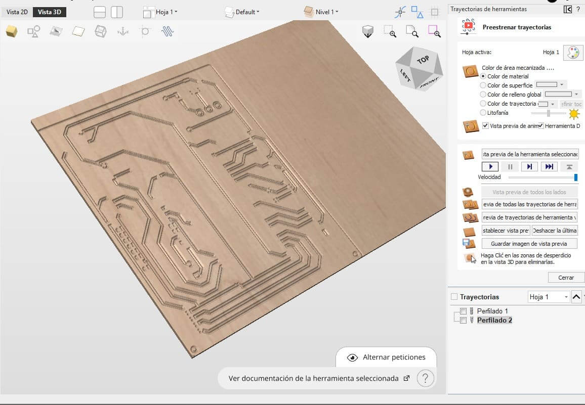
Once all toolpaths were verified through Aspire's simulation environment, the software generated the G-code required by the Roland SRM-20. This file contained the complete machining instructions necessary to fabricate the custom PCB, transforming the digital design into a physical board ready for component assembly and testing.
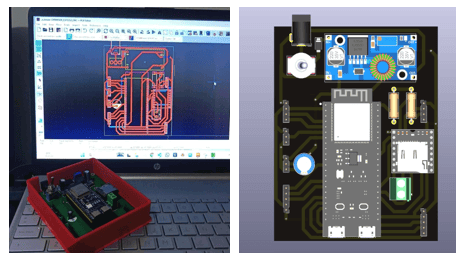
A6.10 3D Visualization and Design Verification
Before manufacturing the PCB, a 3D visualization of the board was generated to verify the placement, orientation, and spatial distribution of all electronic components. This virtual representation made it possible to inspect the overall assembly, identify potential mechanical interferences, and confirm that the connectors, headers, and modules were correctly positioned.
The 3D view also served as a valuable tool for validating the final appearance of the custom PCB and ensuring compatibility with the acrylic structure and the modular design of TYMKA. Performing this verification step prior to fabrication reduced the risk of assembly errors and streamlined the integration process between the electronic, mechanical, and structural components of the project.
A6.11 PCB Milling Process with the Roland SRM-20
After generating the G-code in Aspire, the fabrication process was carried out using the Roland SRM-20 CNC milling machine. A copper-clad bakelite board was securely fixed to the machine bed to ensure stability and machining accuracy throughout the process.
The Roland SRM-20 followed the predefined toolpaths to precisely engrave the conductive traces by removing the excess copper around them. This subtractive manufacturing process enabled the creation of the electrical pathways and soldering pads required for the custom TYMKA PCB.
The milling operation was continuously monitored to verify proper tool performance, cutting depth, and trace quality. Once the engraving process was completed, the fabricated board was inspected to ensure that all conductive paths were correctly isolated and ready for the subsequent drilling, assembly, and soldering stages.
A6.12 PCB Assembly and Soldering
Once the PCB milling process was completed, all electronic components were assembled and soldered onto the custom board. This stage involved placing the passive and active components according to the schematic and PCB layout previously designed in KiCad.
Special attention was given to component orientation, solder joint quality, and electrical continuity to ensure reliable operation. Female headers were installed to mount the ESP32-S3 Dev Kit C N16R8, while connectors for the input and output modules were integrated to facilitate future maintenance and modularity.
After assembly, visual inspections and continuity tests were performed using a digital multimeter to verify correct soldering and identify potential short circuits or open connections. These validation steps ensured that the custom PCB was fully functional and ready for system integration and firmware testing.
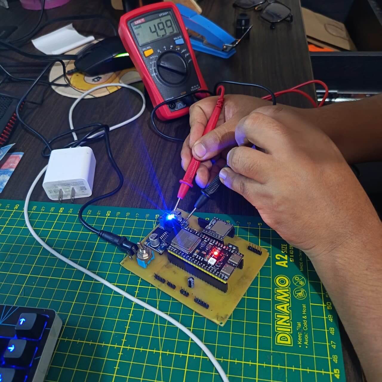
A6.13 Power Supply Validation and Voltage Measurement
To ensure reliable operation of all modules integrated into TYMKA, the power distribution system was validated by measuring the output voltage of the LM2596 DC-DC step-down converter using a digital multimeter.
The LM2596 module converts the input voltage supplied through the power jack into a stable output voltage of approximately 5 V, which is required to power the servo motor, LED matrix, ultrasonic sensor, DFPlayer Mini, OLED display, and other peripheral devices. The output voltage was adjusted and verified before connecting the electronic components to prevent potential damage caused by overvoltage.
After assembly, visual inspections and continuity tests were performed using a digital multimeter to verify correct soldering and identify potential short circuits or open connections. These validation steps ensured that the custom PCB was fully functional and ready for system integration and firmware testing.
The Embedded Programming assignment was fundamental to bringing TYMKA to life by enabling communication and interaction between all input and output devices. During this stage, I developed the firmware for the ESP32-S3 Dev Kit C N16R8 using Arduino IDE, allowing the microcontroller to process sensor data, control actuators, and manage the overall operation of the platform.
The program integrates multiple modules, including the joystick, DHT11 temperature and humidity sensor, ultrasonic sensor, OLED display, LED matrix, servo motor, and DFPlayer Mini audio system. Through embedded programming, these components work together to create an interactive learning experience where users can visualize sensor data, control outputs, and understand the relationship between hardware and software.
This assignment strengthened my understanding of microcontroller programming, library integration, pin configuration, communication protocols, and real-time system management. The resulting firmware became the core logic of TYMKA, enabling the platform to function as a modular and educational tool for learning electronics and embedded systems.
#include <Wire.h>
#include <Adafruit_GFX.h>
#include <Adafruit_SSD1306.h>
#include <DHT.h>
#include <ESP32Servo.h>
#include <MD_MAX72xx.h>
#include <SPI.h>

// ---------------- OLED ----------------
#define SCREEN_WIDTH 128
#define SCREEN_HEIGHT 64

#define OLED_SDA 5
#define OLED_SCL 4

Adafruit_SSD1306 display(SCREEN_WIDTH, SCREEN_HEIGHT, &Wire, -1);

// ---------------- DHT11 ----------------
#define DHTPIN 6
#define DHTTYPE DHT11

DHT dht(DHTPIN, DHTTYPE);

// ---------------- SERVO ----------------
#define SERVO_PIN 7
Servo servo;
int servoAngle = 45;

// ---------------- JOYSTICK ----------------
#define JOY_X 10
#define JOY_Y 9
#define JOY_SW 8

// ---------------- HC-SR04 ----------------
#define TRIG_PIN 21
#define ECHO_PIN 47

// ---------------- MAX7219 ----------------
#define HARDWARE_TYPE MD_MAX72XX::FC16_HW
#define MAX_DEVICES 1

#define DIN_PIN 14
#define CLK_PIN 12
#define CS_PIN 13

MD_MAX72XX mx(
  HARDWARE_TYPE,
  DIN_PIN,
  CLK_PIN,
  CS_PIN,
  MAX_DEVICES
);

// ---------------- SNAKE ----------------

struct Point {
  int x;
  int y;
};

Point snake[64];
Point fruit;

int snakeLength = 3;

enum Direction {
  UP,
  DOWN,
  LEFT,
  RIGHT
};

Direction dir = RIGHT;

unsigned long lastMove = 0;
const int moveInterval = 250;

// =========================================

void createFruit()
{
  bool valid = false;

  while (!valid)
  {
    valid = true;

    fruit.x = random(0, 8);
    fruit.y = random(0, 8);

    for (int i = 0; i < snakeLength; i++)
    {
      if (snake[i].x == fruit.x &&
          snake[i].y == fruit.y)
      {
        valid = false;
      }
    }
  }
}

// =========================================

void drawSnake()
{
  mx.clear();

  for (int i = 0; i < snakeLength; i++)
  {
    mx.setPoint(
      snake[i].y,
      snake[i].x,
      true
    );
  }

  mx.setPoint(
    fruit.y,
    fruit.x,
    true
  );

  mx.update();
}

// =========================================

void moveSnake()
{
  for (int i = snakeLength; i > 0; i--)
  {
    snake[i] = snake[i - 1];
  }

  switch (dir)
  {
    case UP:
      snake[0].y--;
      break;

    case DOWN:
      snake[0].y++;
      break;

    case LEFT:
      snake[0].x--;
      break;

    case RIGHT:
      snake[0].x++;
      break;
  }

  if (snake[0].x < 0) snake[0].x = 7;
  if (snake[0].x > 7) snake[0].x = 0;

  if (snake[0].y < 0) snake[0].y = 7;
  if (snake[0].y > 7) snake[0].y = 0;

  if (snake[0].x == fruit.x &&
      snake[0].y == fruit.y)
  {
    if (snakeLength < 63)
    {
      snakeLength++;
    }

    createFruit();
  }
}

// =========================================

float readDistance()
{
  digitalWrite(TRIG_PIN, LOW);
  delayMicroseconds(2);

  digitalWrite(TRIG_PIN, HIGH);
  delayMicroseconds(10);

  digitalWrite(TRIG_PIN, LOW);

  long duration = pulseIn(ECHO_PIN, HIGH, 30000);

  float distance = duration * 0.0343 / 2.0;

  return distance;
}

// =========================================

void setup()
{
  Serial.begin(115200);

  Wire.begin(OLED_SDA, OLED_SCL);

  if (!display.begin(
        SSD1306_SWITCHCAPVCC,
        0x3C))
  {
    while (1);
  }

  display.clearDisplay();
  display.setTextColor(WHITE);

  display.setTextSize(2);
  display.setCursor(0, 0);
  display.println("TYMKA");

  display.setTextSize(1);
  display.println("Fab Academy 26");

  display.display();

  delay(2000);

  dht.begin();

  ESP32PWM::allocateTimer(0);

  servo.setPeriodHertz(50);
  servo.attach(
    SERVO_PIN,
    500,
    2400
  );

  servo.write(servoAngle);

  pinMode(TRIG_PIN, OUTPUT);
  pinMode(ECHO_PIN, INPUT);

  pinMode(JOY_SW, INPUT_PULLUP);

  mx.begin();
  mx.clear();

  snake[0] = {3, 3};
  snake[1] = {2, 3};
  snake[2] = {1, 3};

  randomSeed(micros());

  createFruit();
  drawSnake();
}

// =========================================

void loop()
{
  int xValue = analogRead(JOY_X);
  int yValue = analogRead(JOY_Y);

  if (yValue > 3000)
  {
    dir = UP;
  }
  else if (yValue < 1000)
  {
    dir = DOWN;
  }
  else if (xValue < 1000)
  {
    dir = LEFT;
  }
  else if (xValue > 3000)
  {
    dir = RIGHT;
  }

  if (millis() - lastMove > moveInterval)
  {
    moveSnake();
    drawSnake();

    lastMove = millis();
  }

  float temp = dht.readTemperature();
  float dist = readDistance();

  display.clearDisplay();

  display.setTextSize(1);

  display.setCursor(0, 0);
  display.print("TEMP: ");

  if (isnan(temp))
    display.print("--");
  else
    display.print(temp, 1);

  display.print(" C");

  display.setCursor(0, 20);
  display.print("DIST: ");
  display.print(dist, 1);
  display.print(" cm");

  display.setCursor(0, 40);
  display.print("ANGLE: ");
  display.print(servoAngle);
  display.print((char)247);

  display.display();

  delay(20);
}
The Input Devices assignment was essential for enabling user interaction and environmental sensing within TYMKA. During this stage, I integrated multiple sensors and input modules into the custom ESP32-S3 PCB, allowing the platform to collect data and respond to user actions in real time.
The input system includes a joystick for navigation and interaction, an ultrasonic sensor for distance measurement, and a DHT11 sensor for monitoring temperature and humidity. These devices provide different types of input data, helping users understand how sensors operate, how signals are acquired, and how microcontrollers process information.
This assignment strengthened my understanding of sensor integration, signal acquisition, pin configuration, and data processing within embedded systems. The successful implementation of these input devices transformed TYMKA into an interactive educational platform, allowing users to explore the relationship between physical inputs and digital responses.
The Output Devices assignment was essential for transforming the data collected by TYMKA into visual, physical, and auditory feedback. During this stage, I integrated multiple output modules with the ESP32-S3, allowing users to observe how a microcontroller processes information and generates responses in real time.
The output system includes an OLED display for visualizing temperature, distance, and system status information, a MAX7219 LED matrix for interactive activities such as the snake game, a SG90 servo motor for demonstrating motion control, and a DFPlayer Mini connected to an 8Ω speaker for audio feedback. These devices provide different forms of output, creating a more engaging and intuitive learning experience.
This assignment strengthened my understanding of actuator control, display interfaces, communication protocols, and multimedia integration in embedded systems. The successful implementation of these output devices enhanced the interactivity and educational value of TYMKA, helping users better understand the relationship between sensor inputs, data processing, and system responses.
The Networking and Communications assignment expanded the capabilities of TYMKA by enabling communication between devices and demonstrating how data can be transmitted and shared within embedded systems. During this stage, which was developed at the Universidad del Pacífico, I explored communication protocols and their applications for integrating multiple modules into a cohesive system.
For TYMKA, communication protocols such as I2C, SPI, UART, and digital interfaces were implemented to connect and manage different input and output devices. The OLED display communicates through I2C, the MAX7219 LED matrix uses SPI, and the DFPlayer Mini audio module operates through UART communication with the ESP32-S3. These protocols allow efficient data exchange between the microcontroller and the connected modules.
This assignment strengthened my understanding of serial communication, data transmission, and protocol integration in embedded systems. The knowledge gained was essential for ensuring reliable communication among all components, enabling TYMKA to function as a fully integrated and interactive educational platform.
The System Integration assignment was crucial for bringing together all the mechanical, electronic, and software components of TYMKA into a single functional educational platform. During this stage, I integrated the custom ESP32-S3 PCB, input and output modules, power management system, acrylic structure, 3D-printed enclosures, and embedded firmware to ensure seamless interaction between all elements.
Following the advice of my instructor, Roberto Delgado, I reconsidered my initial approach of using traditional jumper wires to connect the modules. Instead, I implemented conductive copper tape pathways to create visible and organized electrical connections. This decision significantly improved the aesthetics, usability, and educational value of the project by allowing users to easily understand how signals travel between components while reducing cable clutter.
This assignment strengthened my understanding of multidisciplinary integration, system optimization, and user-centered design. The final result was a cleaner, more intuitive, and fully integrated platform that combines digital fabrication, electronics, and embedded programming into an engaging hands-on learning experience.