Week 15
System Integration
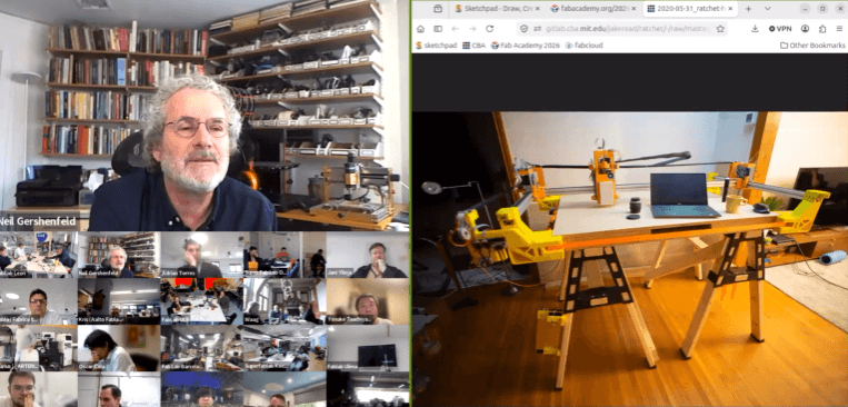
Class with Neil
During the System Integration week lecture with Neil, we learned how to combine all the individual assignments developed throughout Fab Academy into a single functional final project. The class focused on understanding how electronics, programming, mechanical structures, power systems, input/output devices, and digital fabrication processes must work together as one complete integrated system. Neil emphasized that successful system integration is not only about making the project functional, but also about organizing the components efficiently and designing the project to look like a finished product.
Another important topic discussed during the class was the importance of planning the integration process before fabrication and assembly. We learned how CAD models, wiring diagrams, block diagrams, and system architecture sketches help prevent integration problems during the final stages of development. This week helped me better understand how to organize power distribution, communication between modules, packaging methods, and structural assembly for my final project using the ESP32 S3, MP3 module, voltage regulation system, and custom electronic integration.
Have you answered these questions?
- I. made a plan for system integration for your final project? ✅
- II.documented your plan with CAD and/or sketches for system integration? ✅
- III.implemented methods of packaging? ✅
- IV. documented system integration of your final project?✅
- V. linked to your system integration documentation from your final project page? ✅
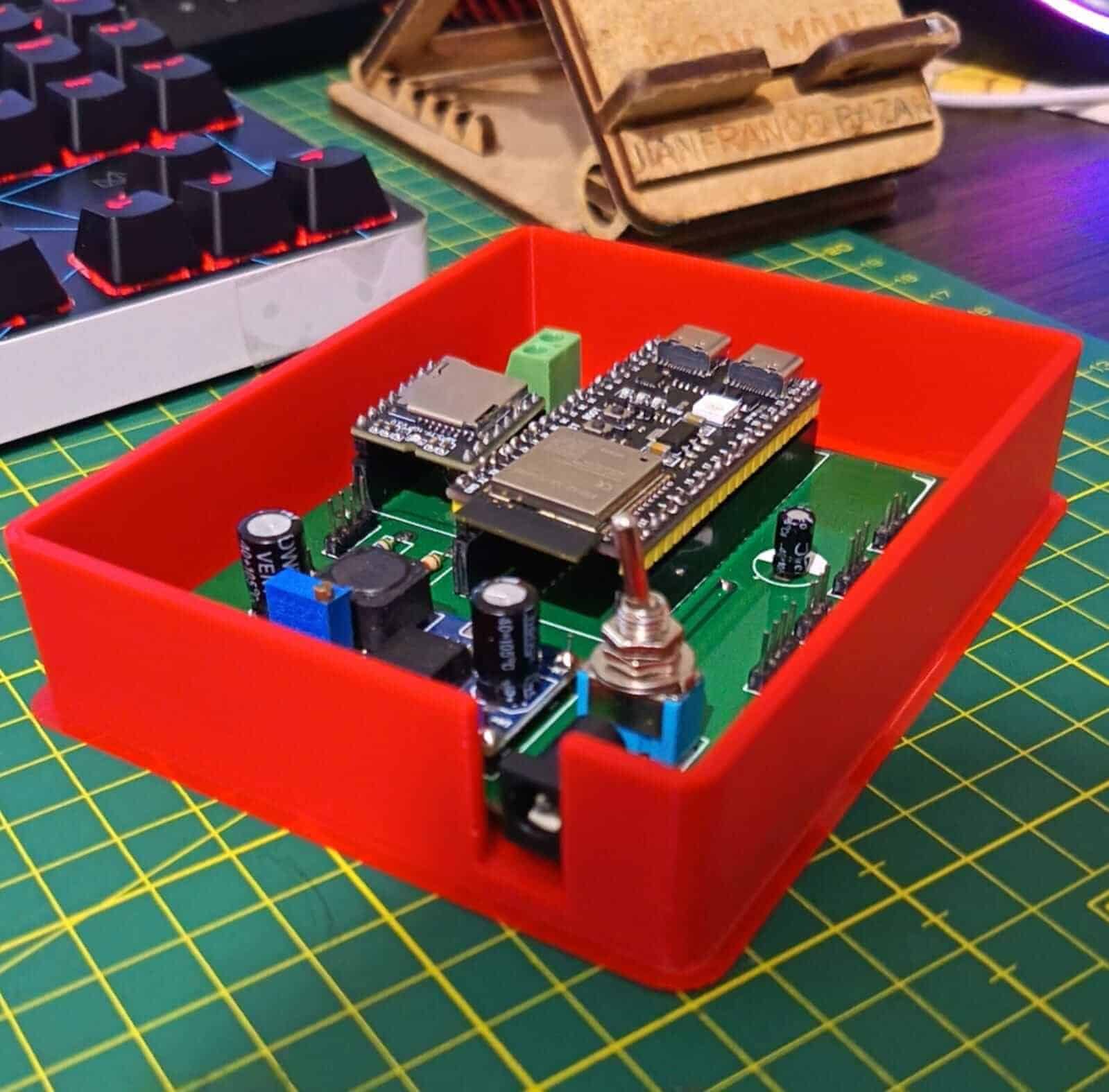
Hero Shot
This section should present the final integrated system of the project as a finished product. The hero shot must clearly show the complete electronic system assembled and powered on, including the ESP32 S3 Dev Kit, OLED display, MP3 module, speaker, switches, connectors, and all integrated input/output components. The objective of this section is to visually demonstrate the final appearance, functionality, and packaging of the project as a complete prototype.
Additionally, the hero shot should highlight the organization of the wiring, PCB assembly, and enclosure or structural integration. A clean and professional presentation helps communicate the final product quality and reflects the successful integration of electronics, programming, and fabrication processes developed during the assignment.
Individual Assignment:
° From this activity, I learned that interface programming is an important part of creating interactive digital fabrication projects. I also understood that different software tools provide different levels of flexibility and complexity depending on the application. Working with RemoteXY showed me how quickly a functional interface can be developed, while also helping me improve my problem-solving skills during the communication and testing process.
1. Introduction
In this assignment, the objective was to design and document the complete system integration of my final project by combining electronic hardware, power management, input/output devices, and embedded programming into a functional prototype. The system was developed around the ESP32 S3 Dev Kit CN 16R8, which acts as the central controller responsible for managing communication between all modules and components.
The project integrates multiple electronic elements such as a power regulation system using the XL4005 step-down module, an OLED display for visual output, an MP3 module with speaker for audio output, switches for system control, and connectors for modular expansion. Through this assignment, I focused on achieving a reliable, organized, and visually finished electronic product while documenting the entire integration workflow.
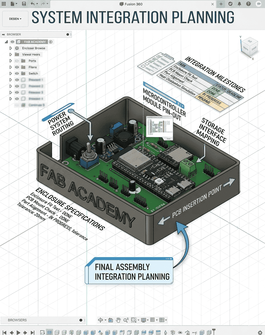
📈2. System Integration Planning
Before assembling the project, I created a system integration plan to organize the connections between the power system, microcontroller, inputs, and outputs. This planning stage helped define how each component would communicate with the ESP32 S3 and how the power distribution would be managed safely and efficiently. The integration strategy also considered future debugging, maintenance, and modularity of the system.
Special attention was given to voltage regulation and connector organization to avoid unstable power delivery. The XL4005 step-down converter was integrated to regulate voltage levels for sensitive components, while female headers and terminal blocks were added to simplify connections and component replacement. This planning process was essential to ensure a stable and scalable electronic system.
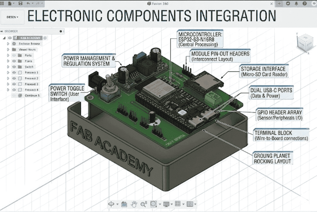
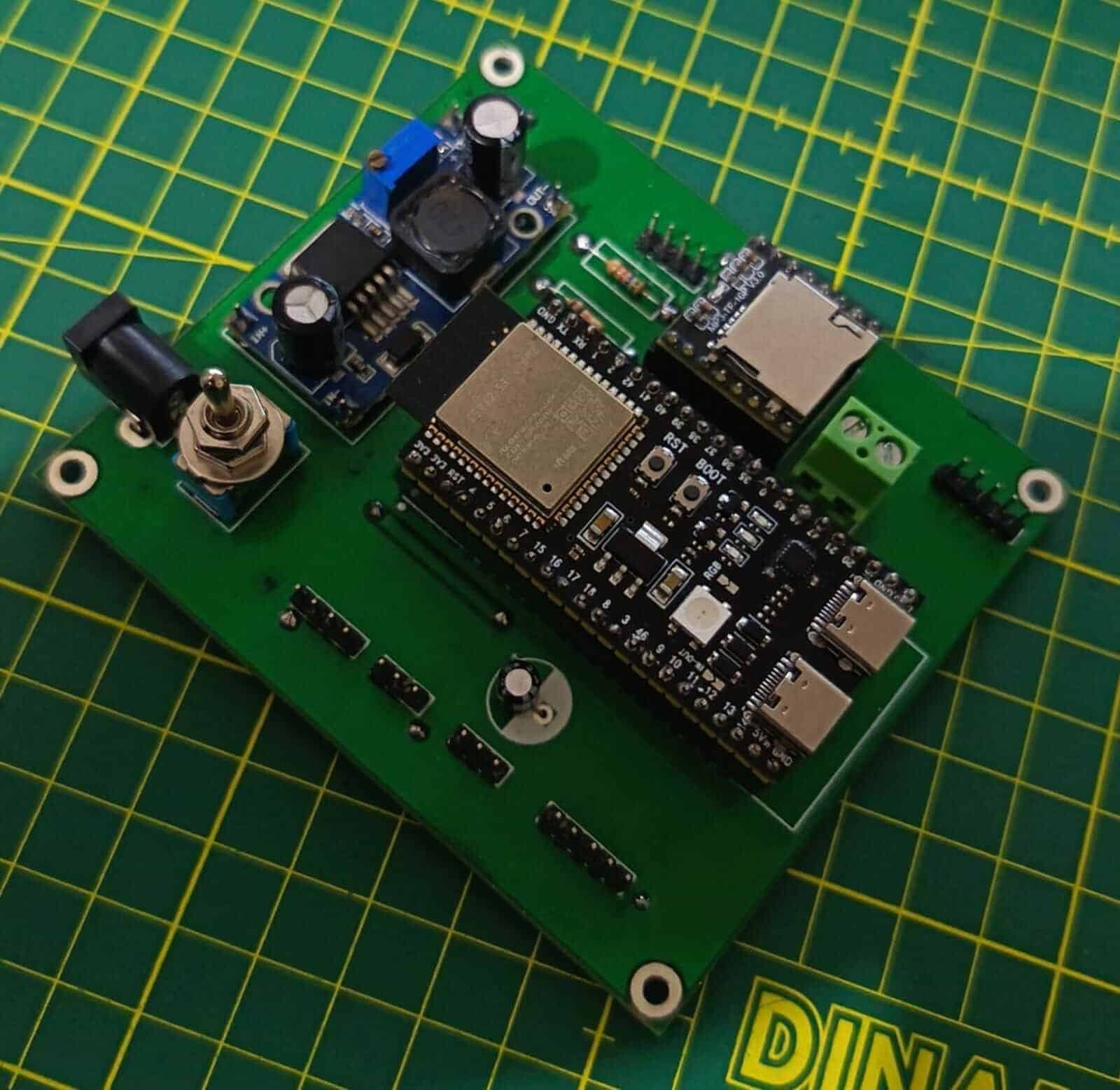
⚙️3. Electronic Components Integration
The electronic integration process involved connecting all essential hardware modules into a single functional system. The ESP32 S3 Dev Kit CN 16R8 was used as the main controller, communicating with the OLED display, MP3 module, and external components through organized PCB connections and headers. Additional components such as Schottky diodes, resistors, capacitors, switches, and connectors were added to improve stability and protection.
The power input section was designed using a DC power jack and a terminal block, allowing external power sources to safely supply the system. The ON-OFF-ON switch was integrated to control different operating states, while the female headers made it easier to connect sensors and output devices without permanent soldering. This integration improved flexibility and usability during testing and future upgrades.
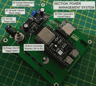
⚙️4. Power Management System
The power management system was designed to provide stable and regulated voltage to all components of the project. A DC power jack connector was used as the main power input, while the XL4005 DC-DC step-down converter regulated the voltage according to the requirements of the ESP32 S3 and peripheral modules. This ensured reliable operation and protected sensitive electronics from voltage fluctuations.
Additional protection components such as the SS34 Schottky diode and 100uF capacitor were incorporated into the PCB to improve current stability and reduce electrical noise. Proper power routing was considered during the PCB design process to avoid overheating, voltage drops, or unstable behavior when operating the audio module and display simultaneously.
5. Input and Output Devices Integration
The system integrates both visual and audio output devices to enhance user interaction. The OLED display was implemented to provide visual information and system feedback, while the MP3 module connected to a speaker enabled audio playback functionality. These output devices were programmed and synchronized through the ESP32 S3 microcontroller.
The integration process required careful pin configuration, voltage management, and communication setup to ensure all modules operated correctly together. Female headers were added to allow easy replacement and testing of components, improving the flexibility and maintainability of the final system.
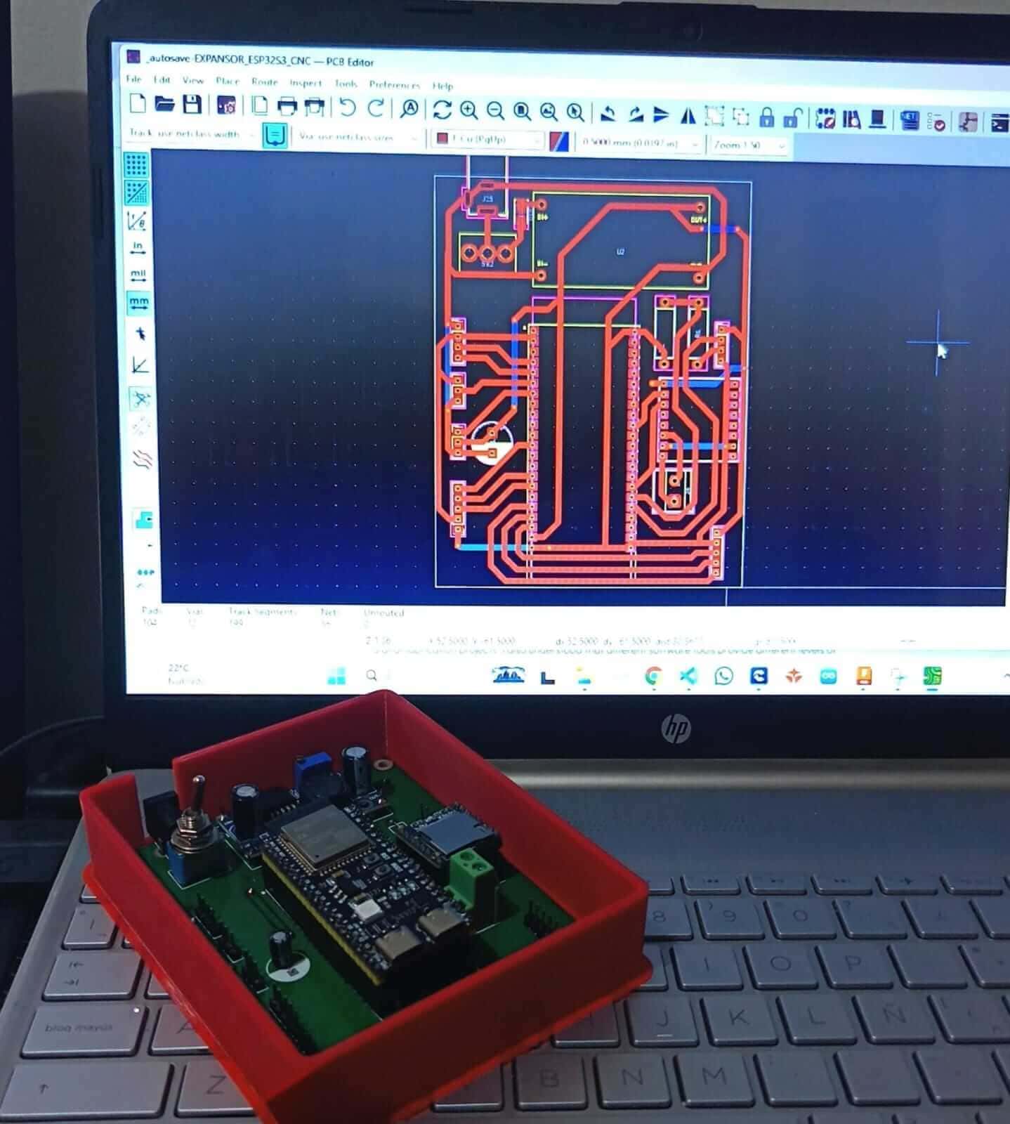
⚙️6. PCB Design and Packaging
The PCB was designed to organize all electronic components into a compact and functional structure. During the design process, attention was given to component placement, trace routing, and connector accessibility to improve assembly and reduce wiring complexity. The final PCB layout was optimized for practical integration and future maintenance.
For packaging, the system was designed to look like a finished product rather than only a prototype. The arrangement of components, connectors, and modules aimed to create a cleaner appearance while maintaining accessibility for debugging and testing. Proper spacing and organization also contributed to better airflow and safer electrical operation.
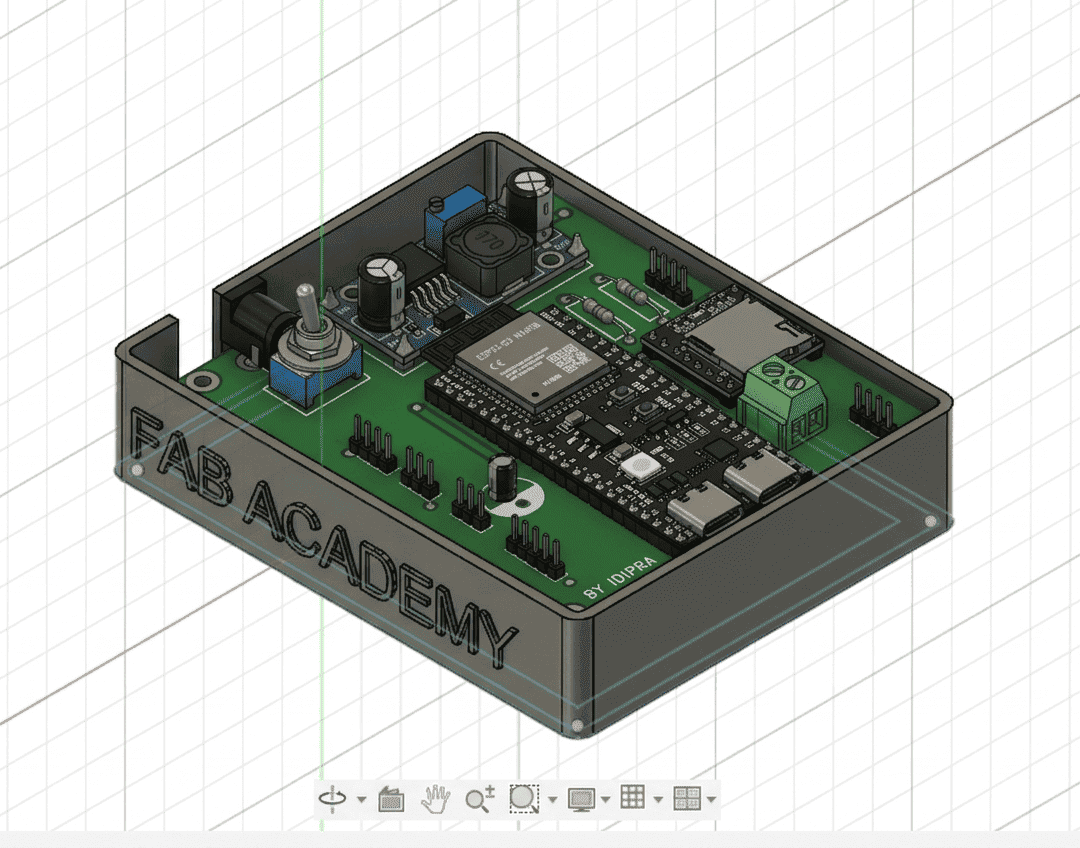
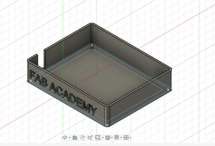
7. CAD Design and Mechanical Integration
CAD sketches and design planning were used to visualize how the electronic components would fit together physically within the final project. This process helped determine the positioning of the OLED display, switches, connectors, speaker, and PCB to achieve a compact and ergonomic design.
Mechanical integration was also important to ensure that cables and components remained secure during operation. The CAD planning stage reduced assembly errors and allowed better organization of the system before fabrication and soldering began.
8. System Testing and Debugging
After integrating all components, several tests were performed to validate the functionality of the complete system. The OLED display, MP3 module, power regulation system, and switches were individually tested before performing full system integration. Debugging included verifying wiring connections, checking voltage stability, and monitoring communication between modules.
During testing, adjustments were made to improve power stability and component synchronization. Serial monitoring tools and multimeter measurements were used to identify connection issues and validate correct operation. This iterative debugging process helped improve the reliability and overall performance of the final prototype.
9. Final System Integration
The final integration combined all electronic, mechanical, and programming elements into a single operational prototype. The ESP32 S3 successfully controlled the OLED display, MP3 module, power system, and external connectors while maintaining stable operation. The project demonstrated how multiple modules can work together within a fully integrated embedded system.
This assignment helped reinforce the importance of planning, PCB organization, power management, and testing during the development of electronic products. The final result represents a functional and visually organized prototype that integrates fabrication, electronics, programming, and system design concepts learned throughout Fab Academy.
10. Individual Reflection
This assignment allowed me to better understand the complete process of system integration in an embedded electronics project. I learned how important it is to carefully organize power distribution, PCB routing, component placement, and communication between modules to achieve a stable and functional system. Working with the ESP32 S3, OLED display, MP3 module, and power regulation components helped me strengthen my skills in electronics integration and debugging.
One of the most valuable lessons from this assignment was understanding how all areas of digital fabrication come together in a final product, including electronics design, programming, CAD planning, manufacturing, and testing. Through this process, I improved my ability to solve integration problems, optimize component organization, and design a prototype that looks more like a finished product rather than only a development project.
Files
Here are the project files available for download:
- Here the File Fusion360: Download .rar
- Here the File STL: Download .rar